Matrox CronosPlus Installation And Hardware Reference
- Taper
- Installation And Hardware Reference

Matrox CronosPlus
Installation and Hardware Reference
Manual no. 10860-101-0100
January 20, 2003
ox Meteor-II /Digital

Matrox
®
is a registered trademark of Matrox Electronic Systems Ltd.
Windows
®
are registered trademarks of Microsoft Corporation.
Intel
®
is a registered trademark of Intel Corporation.
Pentium
®
is a registered trademark of Intel Corporation.
All other nationally and internationally recognized trademarks and
tradenames are hereby acknowledged.
© Copyright Matrox Electronic Systems Ltd., 2003. All rights reserved.
Limitation of Liabilities: In no event will Matrox or its suppliers be liable for
any indirect, special, incidental, economic, cover or consequential
damages arising out of the use of or inability to use the product, user
documentation or related technical support, including without
limitation, damages or costs relating to the loss of profits, business,
goodwill, even if advised of the possibility of such damages. In no
event will Matrox and its suppliers’ liability exceed the amount paid by
you, for the product.
Because some jurisdictions do not allow the exclusion or limitation of
liability for consequential or incidental damages, the above limitation,
may not apply to you.
Disclaimer: Matrox Electronic Systems Ltd. reserves the right to make
changes in specifications at any time and without notice. The
information provided by this document is believed to be accurate and
reliable. However, neither Matrox Electronic Systems Ltd. nor its suppliers
assume any responsibility for its use; or for any infringements of patents
or other rights of third parties resulting from its use. No license is granted
under any patents or patent right of Matrox Electronic Systems Ltd.
PRINTED IN CANADA

Contents
Chapter 1: Introduction . . . . . . . . . . . . . . . . . . . . . . . . . . . . . . . . . . 5
Matrox CronosPlus . . . . . . . . . . . . . . . . . . . . . . . . . . . . . . . . . . . . . . . . . . . . . . . . . . . 6
Data transfer. . . . . . . . . . . . . . . . . . . . . . . . . . . . . . . . . . . . . . . . . . . . . . . . . . . 7
Software. . . . . . . . . . . . . . . . . . . . . . . . . . . . . . . . . . . . . . . . . . . . . . . . . . . . . . . . . . . . 7
Essentials to get started . . . . . . . . . . . . . . . . . . . . . . . . . . . . . . . . . . . . . . . . . . . . . . . . 8
Inspecting the Matrox CronosPlus package . . . . . . . . . . . . . . . . . . . . . . . . . . . . . . . . . 9
Standard package . . . . . . . . . . . . . . . . . . . . . . . . . . . . . . . . . . . . . . . . . . . . . . . 9
Optional items . . . . . . . . . . . . . . . . . . . . . . . . . . . . . . . . . . . . . . . . . . . . . . . . . 9
Handling components . . . . . . . . . . . . . . . . . . . . . . . . . . . . . . . . . . . . . . . . . . . 9
Installation overview . . . . . . . . . . . . . . . . . . . . . . . . . . . . . . . . . . . . . . . . . . . . . . . . . 10
Chapter 2: Hardware installation. . . . . . . . . . . . . . . . . . . . . . . . . . 11
Installing Matrox CronosPlus. . . . . . . . . . . . . . . . . . . . . . . . . . . . . . . . . . . . . . . . . . . 12
Connecting external devices to Matrox CronosPlus . . . . . . . . . . . . . . . . . . . . . . . . . . 14
Chapter 3: Using multiple Matrox CronosPlus boards . . . . . . . . 17
Multiple board installation. . . . . . . . . . . . . . . . . . . . . . . . . . . . . . . . . . . . . . . . . . . . . 18
Grabbing simultaneously from different boards . . . . . . . . . . . . . . . . . . . . . . . . . . . . . 18
Chapter 4: Hardware reference . . . . . . . . . . . . . . . . . . . . . . . . . . . 21
Matrox CronosPlus hardware reference . . . . . . . . . . . . . . . . . . . . . . . . . . . . . . . . . . . 22
Grab features . . . . . . . . . . . . . . . . . . . . . . . . . . . . . . . . . . . . . . . . . . . . . . . . . . . . . . . 23
Performance . . . . . . . . . . . . . . . . . . . . . . . . . . . . . . . . . . . . . . . . . . . . . . . . . . 23
Input channels . . . . . . . . . . . . . . . . . . . . . . . . . . . . . . . . . . . . . . . . . . . . . . . . 23
Low-pass filter . . . . . . . . . . . . . . . . . . . . . . . . . . . . . . . . . . . . . . . . . . . . . . . . 24
Video decoder. . . . . . . . . . . . . . . . . . . . . . . . . . . . . . . . . . . . . . . . . . . . . . . . . 24
Trigger . . . . . . . . . . . . . . . . . . . . . . . . . . . . . . . . . . . . . . . . . . . . . . . . . . . . . . . . . . . . 24

User bits . . . . . . . . . . . . . . . . . . . . . . . . . . . . . . . . . . . . . . . . . . . . . . . . . . . . . . . . . . 25
PCI interface . . . . . . . . . . . . . . . . . . . . . . . . . . . . . . . . . . . . . . . . . . . . . . . . . . . . . . . 25
Appendix A: Troubleshooting . . . . . . . . . . . . . . . . . . . . . . . . . . . . .27
Troubleshooting. . . . . . . . . . . . . . . . . . . . . . . . . . . . . . . . . . . . . . . . . . . . . . . . . . . . . 28
Common problems and solutions . . . . . . . . . . . . . . . . . . . . . . . . . . . . . . . . . . . . . . . 28
Installation Problems . . . . . . . . . . . . . . . . . . . . . . . . . . . . . . . . . . . . . . . . . . . 28
Grabbing Problems. . . . . . . . . . . . . . . . . . . . . . . . . . . . . . . . . . . . . . . . . . . . . 29
Contacting Matrox . . . . . . . . . . . . . . . . . . . . . . . . . . . . . . . . . . . . . . . . . . . . . . . . . . 30
Appendix B: Technical information. . . . . . . . . . . . . . . . . . . . . . . . .31
Technical information . . . . . . . . . . . . . . . . . . . . . . . . . . . . . . . . . . . . . . . . . . . . . . . . 32
General information. . . . . . . . . . . . . . . . . . . . . . . . . . . . . . . . . . . . . . . . . . . . 32
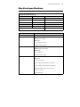
Electrical specifications . . . . . . . . . . . . . . . . . . . . . . . . . . . . . . . . . . . . . . . . . . . . . . . 33
Environmental specifications . . . . . . . . . . . . . . . . . . . . . . . . . . . . . . . . . . . . . . . . . . . 34
Board connectors. . . . . . . . . . . . . . . . . . . . . . . . . . . . . . . . . . . . . . . . . . . . . . . . . . . . 35
BNC connector . . . . . . . . . . . . . . . . . . . . . . . . . . . . . . . . . . . . . . . . . . . . . . . 35
Video input connector . . . . . . . . . . . . . . . . . . . . . . . . . . . . . . . . . . . . . . . . . . 36
Appendix C: Glossary . . . . . . . . . . . . . . . . . . . . . . . . . . . . . . . . . . .37
Index
Regulatory Compliance
Product support

Chapter
1
Introduction
This chapter outlines the key features of the Matrox
CronosPlus board.

6 Chapter 1: Introduction
Matrox CronosPlus
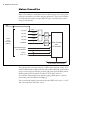
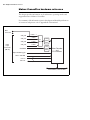
Matrox CronosPlus is a standard monochrome and composite color analog frame
grabber for extremely cost-sensitive imaging applications. This board is available
in a PCI form factor and can acquire different types of standard video formats
using its video decoder.
The video decoder can accept composite (CVBS) and component S-video (Y/C)
in NTSC/PAL formats, and monochrome video in RS-170/CCIR. Grabbed data
can be converted into the following formats with square pixels: BGR32 packed,
BGR24 packed, YUV16 packed (stored in YUYV format), and 8-bit
monochrome. Formatting features include cropping (ROI capture), arbitrary
downscaling, and vertical/horizontal flipping.
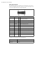
You can attach and switch between 4 monochrome/CVBS video sources, or 1 Y/C
and 3 monochrome/CVBS video sources.
VID_IN0
VID_IN1
VID_IN3
VID_IN2
Opto-isolated trigger
4:1
MUX
Low-
pass
filter
Low-
pass
filter
Video Decoder
and
PCI Interface
32-bit 33MHz, Host PCI Bus
BNC
connector
User in
CHROMA
User out
User in with IRQ
CVBS0 / Y
CVBS1
CVBS2
CVBS3
Video
Input
Connector
(DB-25)
C
2
4

Software 7
Matrox CronosPlus accepts an external trigger input, and operates in next valid
frame/field mode when grabbing upon a trigger. In addition, to control or
synchronize with other devices, the board can accept 3 user input TTL signals and
generate 4 user output TTL signals.
Data transfer
The Matrox CronosPlus board allows the transfer of live video to Host memory
or off-board display memory. Matrox CronosPlus also features a 32-bit/33 MHz
PCI bus master to reduce CPU usage. The board can also generate interrupts for
the start and end of a field, frame, and sequence capture.
Software
To operate Matrox CronosPlus, you can purchase one or more Matrox Imaging
software products that support the Matrox CronosPlus board. These are the
Matrox Imaging Library (MIL) and its derivatives (MIL-Lite, ActiveMIL,
ActiveMIL-Lite, and Matrox Inspector). All Matrox software is supported under
Windows; consult your software manual for supported Windows environments.
❖ Note that, although other software products might be available to operate Matrox
CronosPlus, the discussion throughout this manual is based in terms of Matrox
Imaging software products.
MIL MIL is a development library which provides an extensive list of functions used
to capture, process, analyze, transfer, display, and archive images. Processing and
analysis operations include: spatial filtering, morphological, measurement, blob
analysis, optical character recognition (OCR), pattern recognition (normalized
grayscale correlation and Geometric Model Finder), matrix/bar code reading, and
calibration operations.
MIL-Lite MIL-Lite is a subset of MIL. It includes all the MIL functions for image
acquisition, transfer, display control, and archiving.
ActiveMIL ActiveMIL is a set of ActiveX controls that are based on MIL. ActiveMIL was
designed for rapid application development (RAD) tools, such as Microsoft’s
Visual Basic. ActiveMIL is included with MIL (ActiveMIL-Lite is included with
MIL-Lite).
Matrox Inspector Matrox Inspector is an interactive Windows application for image capture,
processing, analysis, and archiving.

8 Chapter 1: Introduction
MIL application developers can use Matrox Inspector as a prototyping tool to
quickly build proof-of-concept demonstrations for their machine vision, image
analysis, and medical imaging system. End users can use Matrox Inspector to
perform and automate image enhancement and measurement tasks.
Matrox Intellicam Matrox Intellicam is an interactive Windows program that allows fast camera
interfacing and provides interactive access to all the acquisition features of your
Matrox board. With Matrox Intellicam, you can change the size and position of
the active region by creating a custom DCF. Matrox Intellicam is included with
all Matrox Imaging software products.
Essentials to get started
To begin using Matrox CronosPlus, you must have a computer with the following:
• An available conventional 3.3 V or 5 V PCI expansion slot (bus-master capable).
• Processor with an Intel 32-bit architecture (IA32) or equivalent.
Other useful
considerations
• A computer with a relatively up-to-date PCI chipset, such as the Intel 440BX,
810, 815E, 820, 840, or 850 for full Matrox CronosPlus functionality. These
chipsets are recommended because they generally offer better performance in
terms of data transfer rates.
• Microsoft Windows if using Matrox Imaging software (consult the documentation
accompanying the software for specific supported environments and computer
memory/storage requirements).
❖ Matrox CronosPlus is not supported under Windows NT.
• A CD drive, and a hard disk or network drive on which to install the Matrox
CronosPlus software.

Inspecting the Matrox CronosPlus package 9
Inspecting the Matrox CronosPlus package
When you unpack your Matrox CronosPlus package, you should check its
contents. Note that optional parts might or might not be included, depending on
what you ordered. If something is missing or damaged, contact your Matrox
representative.
Standard package
If you ordered Matrox CronosPlus, you should receive the following items:
• The Matrox CronosPlus base board.
•The Matrox CronosPlus Installation and Hardware Reference manual (this
document).
Optional items
You might have also ordered one or more of the following:
• MIL-32/CD, which includes ActiveMIL; MIL-LITE/CD, which includes
ActiveMIL-Lite; or Matrox INSPECTOR-32/CD. Matrox Intellicam is included
with each of the aforementioned software packages.
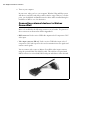
• DB25-TO-5BNC/O cable, an 8-inch input cable with a 25-pin female DB-25
connector on one end and 5 BNCs and open-ended wires on the other end.
Handling components
The electronic circuits in your computer and the circuits on Matrox CronosPlus
are sensitive to static electricity and surges. Improper handling can seriously
damage the circuits. Be sure to follow these precautions:
• Drain static electricity from your body by touching a metal fixture (or ground)
before you touch any electronic component.
• Avoid letting your clothing come in contact with the circuit boards or
components.
Caution Before you add or remove devices from your computer, always turn off the power
to your computer and all peripherals
.

10 Chapter 1: Introduction
Installation overview
The installation procedure consists of the following steps:
1. Complete the hardware installation as described in Chapter 2. If you have any
problems, refer to Appendix A.
2. Complete the software installation procedure as described in the documentation
accompanying your software package.
More information For information on using multiple Matrox CronosPlus boards, refer to Chapter 4,
and for in-depth hardware information, refer to Chapter 5.
If you want technical information about Matrox CronosPlus, including
specifications and connector pinouts and descriptions, refer to Appendix B.
Conventions When the term Host is used in this manual, it refers to your computer.
This manual occasionally makes reference to a MIL-Lite function. However,
anything that can be accomplished with MIL-Lite can also be accomplished with
MIL, ActiveMIL, ActiveMIL-Lite, or Matrox Inspector.
1
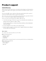
Need help? Appendix A offers solutions to potential problems. If your Matrox CronosPlus
installation questions are not answered in this manual, contact your local Matrox
representative, Matrox Sales Office, or Matrox Imaging Customer Support Group
(see the Customer Support section at the back of this manual for telephone
numbers).
In the unlikely event of a failure, the warranty and Product Assistance Request Form
at the back of this manual outlines return conditions and procedures.
1. Most items can be accomplished with Matrox Inspector.

Chapter
2
Hardware
installation
This chapter explains how to install the Matrox CronosPlus
hardware.

12 Chapter 2: Hardware installation
Installing Matrox CronosPlus
Before you install your board, some precautionary measures must be taken. Turn
off the power to the computer and its peripherals, and drain static electricity from
your body (by touching a metal part of the computer chassis). Next, follow the
steps to install your board.
❖ Your board must be installed before you install the software (either MIL or one of
its derivatives).
Use the following steps to install Matrox CronosPlus:
1. Remove the cover from your computer using the instructions from your computer
manual.
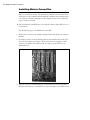
2. Check that you have an empty PCI slot that can accommodate the board. If you
do not have an empty slot, remove a PCI board from your computer to make
room for your Matrox CronosPlus board. Five empty (32-bit) PCI slots are
illustrated below:
3. If present, remove the blank metal plate located at the back of the selected slot.
Keep the removed screw; you will need it to fasten the Matrox CronosPlus board.

Installing Matrox CronosPlus 13
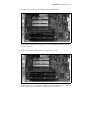
4. Carefully position Matrox CronosPlus in the selected PCI slot.
5. Once perfectly aligned with an empty slot, press the board firmly but carefully
into the connector.
6. Anchor the board by replacing the screw that you removed.
7. Replace the cover of your computer, and connect your video sources. For details,
see the Connecting external devices to Matrox CronosPlus section.

14 Chapter 2: Hardware installation
8. Turn on your computer.
In some cases, when you boot your computer, Windows’ Plug-and-Play system
will detect a new PCI board and you will be asked to assign a driver to it. At this
point, you should click on Cancel because the driver will be installed during the
installation of MIL or one of its derivatives.
Connecting external devices to Matrox
CronosPlus
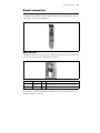
Matrox CronosPlus has the following connectors on its bracket. The pinouts of
these connectors are discussed in detail in Appendix B.
• BNC connector. Used to receive CVBS video input 0 or the Y component of Y/C
video input.
• Video input connector (DB-25). Used to receive CVBS video input or the C
component of Y/C video input. It is also used to transmit/receive user signals and
camera control signals.
You can connect video sources to Matrox CronosPlus’s video input connector,
using the optional DB25-TO-5BNC/O cable. This cable has a 25-pin female
DB-25 connector on one end and 5 BNCs and open-ended wires on the other end.

Connecting external devices to Matrox CronosPlus 15
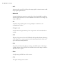
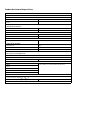
The wires of the cable for video input are listed in the following table:
Wire label Signal Expected input
CH-0 VID_IN0 CVBS video input 0 or
Y component of Y/C video input.
CH-1 VID_IN1 CVBS video input 1.
CH-2 VID_IN2 CVBS video input 2.
CH-3 VID_IN3 CVBS video input 3.
CHROMA CHROMA C component of Y/C video input.

16 Chapter 2: Hardware installation

Chapter
3
Using multiple
Matrox CronosPlus
boards
This chapter explains how to use multiple Matrox
CronosPlus boards.

18 Chapter 3: Using multiple Matrox CronosPlus boards
Multiple board installation
This section describes how to use multiple Matrox CronosPlus boards.
Install each additional Matrox CronosPlus board as you installed the first board
(refer to Chapter 2). In other words, place each additional board in an empty slot.
Theoretically, you can have as many as 16 Matrox CronosPlus boards installed in
your computer at one time; this number is, however, limited by the number of
empty slots in your computer and, for simultaneous grabs, by the available
bandwidth of your computer (discussed later in this chapter).
Using MIL-Lite, you have to allocate a MIL system for each board and allocate
the resources of each MIL system.
Grabbing simultaneously from different
boards
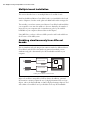
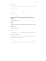
You can simultaneously grab images from cameras attached to different Matrox
CronosPlus boards; however, the number of cameras from which you can
simultaneously grab is determined by the PCI bandwidth available in your
computer.
Matrox CronosPlus is susceptible to PCI bus latency. In addition, sustained
PCI-transfers to memory require the use of a high performance PCI core-logic
chipset, such as the Intel 820, 840, or 850. If a high performance chipset is used
with a Matrox CronosPlus board, you should not have any PCI bandwidth
Camera 1
Camera 2
Matrox CronosPlus
Matrox CronosPlus
Grabbing from two Matrox CronosPlus boards

Grabbing simultaneously from different boards 19
problems when grabbing up to two full-sized color images simultaneously (using
two boards). However, grabbing more than two full-sized color images
simultaneously might result in PCI bandwidth problems.
As a reference point, grabbing one full-sized NTSC or PAL image in real time will
require a PCI bandwidth of 35 Mbytes/sec or 42 Mbytes/sec, respectively, when
transferring in RGBX (32-bit) mode.
When grabbing from three or more Matrox CronosPlus boards simultaneously,
you will have to reduce the image size to avoid reaching the upper limits of the
overall available bandwidth.

20 Chapter 3: Using multiple Matrox CronosPlus boards
La page charge ...
La page charge ...
La page charge ...
La page charge ...
La page charge ...
La page charge ...
La page charge ...
La page charge ...
La page charge ...
La page charge ...
La page charge ...
La page charge ...
La page charge ...
La page charge ...
La page charge ...
La page charge ...
La page charge ...
La page charge ...
La page charge ...
La page charge ...
La page charge ...
La page charge ...
La page charge ...
La page charge ...
La page charge ...
La page charge ...
La page charge ...
La page charge ...
-
 1
1
-
 2
2
-
 3
3
-
 4
4
-
 5
5
-
 6
6
-
 7
7
-
 8
8
-
 9
9
-
 10
10
-
 11
11
-
 12
12
-
 13
13
-
 14
14
-
 15
15
-
 16
16
-
 17
17
-
 18
18
-
 19
19
-
 20
20
-
 21
21
-
 22
22
-
 23
23
-
 24
24
-
 25
25
-
 26
26
-
 27
27
-
 28
28
-
 29
29
-
 30
30
-
 31
31
-
 32
32
-
 33
33
-
 34
34
-
 35
35
-
 36
36
-
 37
37
-
 38
38
-
 39
39
-
 40
40
-
 41
41
-
 42
42
-
 43
43
-
 44
44
-
 45
45
-
 46
46
-
 47
47
-
 48
48


Matrox CronosPlus Installation And Hardware Reference
- Taper
- Installation And Hardware Reference
dans d''autres langues
- English: Matrox CronosPlus
Documents connexes
-
Matrox orion HD Installation And Hardware Manual
-
-
-
-
-
-
-
-
-