
Electrical to Fiber
Optic Transmitter
Convertisseur
Electrique vers
Fibre optique
picoLink Series
FEO-171p
Guide to Installation
and Operation
Notice d'installation et
d'utilisation
M396-9920-101
Copyright 2005
Miranda Technologies Inc.
Specification may be subject to change
Printed in Canada
March 2005
Copyright 2001
Miranda Technologies Inc.
Les spécifications peuvent être modifiées
Imprimé au Canada
Mars 2005
Miranda
Technologies inc.
3499 Douglas-B. Floreani
St-Laurent, Québec, Canada, H4S 1Y6
Tel : 514-333-1772
Fax : 514-333-9828
www.miranda
.com
FEO-171p

2
CONTACT MIRANDA
For technical assistance, please contact the Miranda Technical support centre nearest you:
Pour toute assistance technique, veuillez contacter le centre de support technique de Miranda de votre région:
Americas
Telephone:
+1-800-224-7882
e-mail:
Asia
Telephone:
+81-3-5730-2987
e-mail:
Europe, Middle East,
Africa, UK
Telephone:
+44 (0) 1491 820222
e-mail:
France (only)
Telephone:
+33 (0) 1 55 86 87 88
e-mail:
www.miranda.com

FEO-171p
3
Guide to installation & Operation
1 General ............................................................................. 4
1.1 Introduction................................................................ 4
1.2 Features...................................................................... 4
2 Overall View ...................................................................... 5
3 Installation ....................................................................... 6
3.1 Warning ...................................................................... 6
3.2 Power Supply ............................................................... 6
3.3 4:2:2 video input ......................................................... 6
3.4 Fiber Output ................................................................ 6
3.5 PL-Fiber tray Installation............................................... 7
4 Operation.......................................................................... 8
4.1 Status LED................................................................... 8
5 Specifications.................................................................... 9
Notice d'installation et d'utilisation
1 Généralités...................................................................... 11
1.1 Introduction...............................................................11
1.2 Caractéristiques...........................................................11
2 Présentation.................................................................... 12
3 Installation ..................................................................... 13
3.1 Précaution d'emploi .....................................................13
3.2 Alimentation ..............................................................13
3.3 L'entrée 4:2:2 .............................................................13
3.4 La sortie Fibre optique .................................................13
3.5 Installation dans le PL-Fiber tray ...................................14
4 Exploitation .................................................................... 15
4.1 Signalisation de l'état ..................................................15
5 Spécifications.................................................................. 16

FEO-171p
4
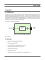
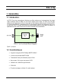
1 General
1.1 Introduction
The FEO-171p is a stand-alone electrical to optical solution for transmitting digital video (SDI,
270 Mbps) signals over a single mode fiber optic link. The FEO-171p can be used for short and
medium haul applications with distances up to 10km. The FEO-171p can be used in conjunction
with the FOE-171p picoLink Optical to Electrical Receivers. The fiber optic picoLink can be used
stand-alone or can be mounted in a special rack-mount tray that turns the picoLink fiber
converters into an electrical to/from optical patch field.
Cost effective, compact and lightweight
Optical
Tx
FEO-171p Functional Block Diagram
FIBER
OUT
4:2:2 IN
Figure 1: Diagram
1.2 Features
• Supports SDI 270 Mbps SMPTE 259M-C
• Conforms to SMPTE 297M
• Laser Transmitter for typical distances up to 10 km
• Single-mode 1310 nm with SC/PC connector
• Valid input signal indication
• Stand alone mounting
• Optional rack mount tray turns picoLink into optical patch field

FEO-171p
5
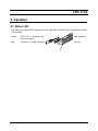
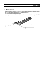
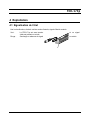
2 Overall View
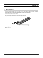
Figure here under illustrates the FEO-171p. The 4:2:2 Video input is made via a BNC connector
and the optic output is made via a Single-mode 1310 nm SC/PC connector
A bicolor Led provides module status.
The power supply is connected to a mini-XLR type connector.
Figure 2: FEO-171p
Bicolor Led

FEO-171p
6
3 Installation
3.1 Warning
Note: Do not dismantle; the fiber optics are fragile and any pinch or fold may damage them.
Hazards for the Operator
Active Laser receptacles emit radiation invisible to the naked eye. Never look directly
into or through the inside of an active receptacle without having previously ensured
that it is not connected to the power supply.
Caution: Although not considered overly dangerous for the eye, avoid accidental
exposure to the optic beam emitted from the fiber optic connectors.
3.2 Power Supply
The power supplies LKS-WSA and LKS-WSE, for 110V and 220V operation respectively, are
used to power the FEO-171p.
Each power supply provides a regulated +5 VDC / 750 mA power source.
The FEO-171p employs a mini XLR-3 Mini QG type (Switchcraft) connector for its power needs.
Figure here under provides a detailed pinout of the male connector.
Pin 1: Shield
Pin 2: GND
Pin 3: +5 VDC
Figure 3: Power supply connector pin out
3.3 4:2:2 video input
BNC type connector: Connect a 4:2:2 SDI signal,
3.4 Fiber Output
Single-mode 1310 nm SC/PC connector
Laser Transmitter for typical distances up to 10 km

FEO-171p
7
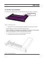
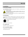
3.5 PL-Fiber tray Installation
PL-Fiber-tray is equipped to house up to 10 pico fiber with dual power supply for redundancy.
Figure 4 : PL-Fiber-tray front view
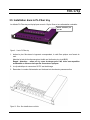
1. Insert pico fiber in the corresponding housing, with SC/PC fiber connector to the front.
Attention Status Led is located at the rear of the pico (BNC side)
Caution: Although not considered overly dangerous for the eye, avoid accidental
exposure to the optic beam emitted from the fiber optic connectors.
2. The clip of the SC/PC connector is used to fasten the pico module
3. Connect the power cord on the 3 pins power socket
Figure 5 : Pico fiber housed in a tray
Pico fiber power supply
connection

FEO-171p
8
4 Operation
4.1 Status LED
The multi-color status LED, located next to the video BNC input connector, indicates the status
of the module.
Green: FEO-171p is powered and has detected a
valid video signal
Red: Overload or signal absence on input.

FEO-171p
9
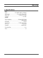
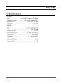
5 Specifications
INPUT
Signal: ................................. 4:2:2 SMPTE 259M-C (270 Mbps)
Cable Length: ................................275 m (900’) (Belden 8281)
Return Loss: ..........................................> 15 dB up to 270 MHz
Connector: ............................................................... 75 Ω BNC
OUTPUT
Signal compatibility:............................ 270 Mbps SMPTE 259M
............................................................................ SMPTE 297M
Wavelength:..................................................................1310 nm
Output Power:....................................... -7.5 dBm (Laser Diode)
Fiber Type: .............................................................Single Mode
Connector:.......................................................... Optical SC/PC
Processing Delay: ............................................................< 5 ns
Power: ................................................................................ 1 W

FEO-171p
10

FEO-171p
11
1 Généralités
1.1 Introduction
Le FEO-171p est un convertisseur électrique vers fibre optique pour la transmission d'un signal
vidéo numérique SDI 270 Mbps via une liaison optique mono mode. Le FEO-171p peut être
utilisé pour des applications court ou long trajet sur des distances allant jusqu'à 10 km. Le FEO-
171p peut être utilisé en combinaison avec le convertisseur optique vers électrique FOE-171p.
Le pico fibre FEO-171p peut être utilisé en module stand alone ou monté dans un châssis 1U
spécialement conçu pour recevoir les pico fibre et équipé d'une alimentation.
Optical
Tx
FEO-171p Functional Block Diagram
FIBER
OUT
4:2:2 IN
Figure 6 : synoptique
1.2 Caractéristiques
• Supporte les signaux SDI 270 Mbps SMPTE 259M-C
• Conforme au standard SMPTE 297M
• Transmission laser pour distances jusqu'à 10 km
• Mono-mode 1310 nm par connecteur SC/PC
• Indication de validité du signal d'entrée
• Autonome
• En option montage en châssis 1U, patch optique

FEO-171p
12
2 Présentation
La figure ci-dessous représente le FEO-171p. L'entrée est raccordée sur un connecteur de type
BNC et la sortie Optique est réalisée par un connecteur de SC/PC
Une Led bicolore indique les différents états.
Le raccordement d'alimentation est réalisé sur le connecteur mini-XLR de type Mini QG
Switchcraft.
.
Figure 7 : FEO-171p
Led bicolore

FEO-171p
13
3 Installation
3.1 Précaution d'emploi
Note : Ne pas démonter, les connections optiques sont très fragiles et un démontage pourrait
causer des dommages irréversibles.
Précautions d'utilisation
Les émetteurs/récepteurs laser émettent des radiations invisibles à l'œil nu. Ne
jamais regarder directement en direction du faisceau d'un connecteur sans s'assurer
que ce dernier n'est pas alimenté.
Attention : même s'il n'y a pas de danger pour l'œil, éviter une exposition accidentelle au
faisceau émis par les connecteurs optiques.
3.2 Alimentation
Les alimentations LKS-WSA et LKS-WSE, alimentent les modules picoLink respectivement à
partir d'un secteur 110 V et 220 V. Ces alimentations délivrent une tension régulée + 5 VDC /
750 mA.
Le raccordement avec l'alimentation se fait par l'intermédiaire d'un connecteur mini XLR –3
points mâles de type Mini QG Switchcraft.
1 : écran
2 : masse
3 : +5 V
Figure 8 : Affectation du connecteur alimentation
3.3 L'entrée 4:2:2
Embase BNC : Raccordez un signal SDI 4:2:2
3.4 La sortie Fibre optique
Connecteur SC/PC mono mode 1310 nm
Liaison optique jusqu'à 10 km

FEO-171p
14
3.5 Installation dans le PL-Fiber tray
Le châssis PL-Fiber-tray est équipé pour recevoir 10 pico fibres et une alimentation redondée.
Figure 9 : Vue du PL-Fiber-tray
1. Insérez le pico fibre dans le logement correspondant, le coté fibre optique vers l'avant du
rack.
Attention la Led de fonctionnement est visible sur l'arrière du pico (coté BNC)
Rappel : Attention : même s'il n'y a pas de danger pour l'œil, éviter une exposition
accidentelle au faisceau émis par les connecteurs optiques.
2. Le clip métallique du connecteur SC/PC sert de blocage
3. Raccordez le cordon d'alimentation sur l'embase trois broches du panneau arrière
Figure 10 : Picos fibre installés dans un châssis
Embase alimentation pour
pico fibre

FEO-171p
15
4 Exploitation
4.1 Signalisation de l'état
Une Led multicolore, située à coté du cordon d'entrée, signale l'état du module.
Vert : Le FEO-171p est sous tension et un signal
vidéo est présent en entrée
Rouge : Surcharge ou absence de signal en entrée

FEO-171p
16
5 Spécifications
ENTRÉE
Signal: ................................. 4:2:2 SMPTE 259M-C (270 Mbps)
Longueur de câble: ........................275 m (900’) (Belden 8281)
Désadaptation: ......................................> 15 dB up to 270 MHz
Connecteur: ............................................................. 75 Ω BNC
SORTIE
Signal: ................................................ 270 Mbps SMPTE 259M
............................................................................ SMPTE 297M
Longueur d'onde:..........................................................1310 nm
Puissance de sortie: ............................. -7.5 dBm (Laser Diode)
Type de fibre:...........................................................Mono Mode
Connecteur:....................................................... Optique SC/PC
Délai de traitement: .........................................................< 5 ns
Consommation: .................................................................. 1 W
-
 1
1
-
 2
2
-
 3
3
-
 4
4
-
 5
5
-
 6
6
-
 7
7
-
 8
8
-
 9
9
-
 10
10
-
 11
11
-
 12
12
-
 13
13
-
 14
14
-
 15
15
-
 16
16


GRASS VALLEY FEO-171p Manual To Installation And Operation
- Taper
- Manual To Installation And Operation
- Ce manuel convient également à
dans d''autres langues
- English: GRASS VALLEY FEO-171p
Autres documents
-
IMG STAGELINE 25.7160 Le manuel du propriétaire
-
Samsung 151P Manuel utilisateur
-
Acer SW5-111P Manuel utilisateur
-
Extron FOXBOX T HD-SDI Manuel utilisateur
-
Extron FOX 3G HD-SDI Manuel utilisateur
-
AJA OG-FIBER-2T-X Manuel utilisateur
-
Miranda ADA-702i Manual To Installation And Operation
-
AJA Hi5-12G Manuel utilisateur
-
AJA FiDO-2T Manuel utilisateur
-
AJA FiDO-TR-12G Manuel utilisateur