La page est en cours de chargement...

12.0996.0004
ROTRONIC AG, CH-8303 Bassersdorf
Tel. +41 44 838 11 44, www.rotronic.com
ROTRONIC Messgeräte GmbH, D-76275 Ettlingen
Tel. +49 7243 383 250, www.rotronic.de
ROTRONIC SARL, 56, F - 77183 Croissy Beaubourg
Tél. +33 1 60 95 07 10, www.rotronic.fr
ROTRONIC Italia srl, I- 20157 Milano
Tel. +39 2 39 00 71 90, www.rotronic.it
ROTRONIC Instruments (UK) Ltd, West Sussex RH10 9EE
Phone +44 1293 571000, www.rotronic.co.uk
ROTRONIC Instrument Corp, NY 11788, USA
Phone +1 631 427-3898, www.rotronic-usa.com
ROTRONIC Canada Inc.,Canada L8W 3P7
Phone + 1 905 754 5164, www.rotronic.ca
ROTRONIC Instruments Pte. Ltd., Singapore 159836
Phone +65 6376 2107, www.rotronic.sg
ROTRONIC Shanghai Rep. Office, Shanghai 200233, China
Phone +86 40 08162018, www.rotronic.cn
A
A
A
A
A
Terminal Description
K2-1 V– Power supply −
K2-2 V+ Power supply +
K2-3 Earth
K3-1 NC Normally closed (relay not energized)
K3-2 COM Common terminal
K3-3 NO Normally open (relay energized)
K4-4 GND
GND
K4-3 GND
K4-2 OUT2 Analog temperature / humidity output +
K4-1 OUT1 Analog differential pressure output +
Terminal K2-3: Earth is usually connected to V–. If this is not wanted, the solder pad B5 on the
PCB must be opened.
Programming
Attention
Make sure that all settings have been made correctly before integrating and connecting
the transmitter in the network.
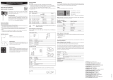
SHORT INSTRUCTION MANUAL
MENU button: open / close menu
ENTER button: select menu point
Menu navigation
Buttons + / - change value:
increase / decrease
Digital Differential Pressure Transmitter
Congratulations for the purchase of your new PF4
transmitter. Please read these short instructions
carefully before installing the device.
General Description
These short instructions are limited to a descrip-
tion of the main functions and installation of
the device. The detailed instruction manual can
be found on the internet at: www.rotronic.com
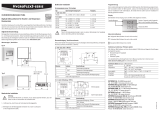
Dimensions / Connections
Commissioning
The device was adjusted in our factory per the accompanying certicate and therefore does not
need to be checked or readjusted during installation. After installation the device must be zeroed
by connecting the two pressure connections and the absolute air pressure (QFE) of the environs
entered into the device.
Mechanical Installation
Mounting with Drill Template
Drill the necessary holes using the drill template drawn
on the packaging. Then insert the plugs delivered with
the device and mount the transmitter with the screws.
Mounting on DIN Top-Hat Rail
The transmitter can be mounted directly on a TS35 DIN top-hat
rail with the AC5002 mounting kit (order separately). For this,
the DIN holders are screwed directly on to the pre-drilled holes
in the transmitter.
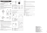
Ethernet
Current Output
Voltage Output
=
~
V+
GND
GND
OUT1
OUT2
V+
GND
GND
OUT1
OUT2
1
2
3
K 2
V –
V +
K4
GND
GND
OUT2
OUT1
4
3
2
1
OUT 1 = Pa
OUT 2 = %RH / °C
1 2 3
NO
NC
COM
K 3
B5
26
12.5
20.5
26
12.5
20.5
Specications
Differential pressure measurement range
-25...+25 Pa / -50…+50 Pa
-100...+100 Pa / -250…+250 Pa
-500...+500 Pa
Measurement range -100...200 °C (depending on probe)
0...100 %RH
Range of application
Storage conditions 0...70 °C / 0…90 %RH
0...60 °C (with display)
Accuracy differential pressure
±1.0 % full scale @23 °C ±3 K,
1,000hPa
Long-term stability sensor ±0.3 % of reading / year
Dependence on ambient pressure 0.1 % of reading / hPa
Leak rate <180 µl/min
Accuracy temperature Probe-dependent
Protection IP65 / IP40 (model with Ethernet)
Outputs 0…1 V / 0…5 V / 0…10 V / 0…20 mA / 4…20 mA
Accuracy, analog output ±10 mV (voltage output), ±20 μA (current output)
Interfaces: Ethernet (option)
HW4 compatibility Version v3.2 / v3.4 (with HC2) and later
Relay switching capacity <50 VAC / <75 VDC / <1 A, congurable with HW4
Housing material ABS
Electrical Installation
Supply Voltage / Current Consumption
Type
Supply Voltage /
Current Consumption
Load Output
PF431
15...40 VDC / 14... 28 VAC
<70 mA
(150 mA @ 15 VDC with Ethernet)
Max. 500 Ω
0...20 mA
PF432 4...20 mA
PF433
Min. 1000 Ω
0...1 V
PF434 0...5 V
PF435 0...10 V
Attention
Wrong supply voltages and excessively high loading of the outputs can damage the
transmitter.
Terminal Conguration / Wiring Diagrams
The type is dened using the table Supply Voltage / Technology and then one of the following
wiring diagrams used:
Unauthorized use of the menus can be blocked with the HW4 software.
The function for this is to be found in
HW4 Software > Device Manager > Display
.
Main Menu Points
Main Menu Submenu Selection / Information
Device Settings
Units
Metric / English
Back Light
Key Press / On / Off
Pressure
Absolute air pressure
Value 1
DiffPress / Humi HC2 / Temp HC2 / Calc / None
Value 2
DiffPress / Humi HC2 / Temp HC2 / Calc / None
Value 3
DiffPress / Humi HC2 / Temp HC2 / Calc / None
Device Information
Version
Firmware version
Serial Nbr
Serial number
Differential Pressure
Unit
Unit of measured value
Filter
Pa / inH2O / mpsi / mbar / mmHg / mmH2O / Torr / g/m2
0 τ63 = 0 s
7 τ63 = 32 s
Adjust
Sensor adjustment
Zero Adjust
Zero adjustment
Probe information (PF4 with HC2 connector)
SensorType
HC2 / Analog In
Scaling / Adjustment / Firmware Update
The following settings can be changed using the HW4 software and a link to your computer per
AC3006 service cable:
• output scale
• adjustment
• rmware update
Attention
The PF4 can just be adjustet with AC3006 cable and external power supply.
You can nd a detailed description in the manual that you can download from our web site at
www.rotronic.com.
Periodic Calibration of the Transmitter
Both the differential pressure sensor and the corresponding electronics are very stable and do
not normally need to be changed or calibrated after factory calibration. For maximum accuracy
we recommend regular calibration of the device.
Attention
Any movement of the sensor or the pipes during calibration and adjustment, will result
in deviated values.
☞
Attention
In order to get the best accuracy the QFE-Pressure has to be programmed.
Use an average QFE-value for your geographic zone.

12.0996.0004
ROTRONIC AG, CH-8303 Bassersdorf
Tel. +41 44 838 11 44, www.rotronic.com
ROTRONIC Messgeräte GmbH, D-76275 Ettlingen
Tel. +49 7243 383 250, www.rotronic.de
ROTRONIC SARL, 56, F - 77183 Croissy Beaubourg
Tél. +33 1 60 95 07 10, www.rotronic.fr
ROTRONIC Italia srl, I- 20157 Milano
Tel. +39 2 39 00 71 90, www.rotronic.it
ROTRONIC Instruments (UK) Ltd, West Sussex RH10 9EE
Phone +44 1293 571000, www.rotronic.co.uk
ROTRONIC Instrument Corp, NY 11788, USA
Phone +1 631 427-3898, www.rotronic-usa.com
ROTRONIC Canada Inc.,Canada L8W 3P7
Phone + 1 905 754 5164, www.rotronic.ca
ROTRONIC Instruments Pte. Ltd., Singapore 159836
Phone +65 6376 2107, www.rotronic.sg
ROTRONIC Shanghai Rep. Office, Shanghai 200233, China
Phone +86 40 08162018, www.rotronic.cn
Klemme Beschreibung
K2-1 V– Spannungsversorgung −
K2-2 V+ Spannungsversorgung +
K2-3 Erde
K3-1 NC Ruhezustand geschlossen (normaly closed)
K3-2 COM Gemeinsamer Anschluss (common)
K3-3 NO Ruhezustand offen (normaly open)
K4-4 GND
GND
K4-3 GND
K4-2 OUT2 Temperatur-/ Feuchte-Analogausgang +
K4-1 OUT1 Differenzdruck-Analogausgang +
Klemme K2-3: Erde ist standardmässig mit V– verbunden. Wird das nicht gewünscht, muss auf
dem PCB das Lötauge B5 geöffnet werden.
Programmierung
Achtung
Stellen Sie sicher, dass alle Einstellungen richtig durchgeführt wurden bevor Sie den
Messumformer ins Netzwerk einbinden und anschliessen.
KURZBEDIENUNGSANLEITUNG
Taste MENU: Menü öffnen / schliessen
Taste ENTER: Auswahl Menüpunkt
Menünavigation
Tasten + / - Wert ändern:
Erhöhen / Verringern
Digitaler Messumformer für Differenzdruck
Wir gratulieren Ihnen zum Kauf Ihres neuen
PF4 Messumformers. Bitte lesen Sie diese
Kurzanleitung genau durch, bevor Sie das Gerät
installieren.
Allgemeine Beschreibung
Diese Kurzbedienungsanleitung beschränkt sich
auf die Beschreibung der wichtigsten Funktionen
und der Installation des Gerätes. Die detaillierte
Bedienungsanleitung finden Sie im Internet
unter: www.rotronic.com
Abmessungen / Anschlüsse
Inbetriebnahme
Das Gerät wurde ab Werk justiert gemäss beiliegendem Zertikat, sodass eine Überprüfung oder
Nachjustierung bei der Installation nicht notwendig ist. Nach der Installation muss mittels Ver-
binden der beiden Druckanschlüsse ein NULL-Abgleich durchgeführt und der absolute Luftdruck
(QFE) der Umgebung im Gerät eingegeben werden.
Mechanische Installation
Montage mit Bohrschablone
Mit der auf der Verpackung aufgezeichneten Bohrschablo-
ne werden die nötigen Löcher gebohrt. Danach werden die
mitgelieferten Dübel eingesetzt und der Messumformer mit
Hilfe der Schrauben montiert.
DIN-Hutschienenmontage
Mit dem Montagekit AC5002 (separat bestellen) kann der Mes-
sumformer direkt auf eine DIN-Hutschiene TS35 montiert werden.
Hierzu werden die DIN-Halterungen direkt auf die vorgebohrten
Löcher des Messumformers geschraubt.
A
Stromausgang
Spannungsausgang
=
~
V+
GND
GND
OUT1
OUT2
V+
GND
GND
OUT1
OUT2
Ethernet
1
2
3
K 2
V –
V +
K 4
GND
GND
OUT2
OUT1
4
3
2
1
OUT 1 = Pa
OUT 2 = %rF / °C
1 2 3
NO
NC
COM
K 3
B5
☞
26
12.5
20.5
26
12.5
20.5
Technische Daten
Differenzdruck Messbereich -25...+25 Pa / -50…+50 Pa
-100...+100 Pa / -250…+250 Pa / -500...+500 Pa
Messbereich -100...200 °C (je nach Fühler)
0...100 %rF
Einsatzbereich / Lagerbedingungen 0...70 °C / 0…90 %rF
0...60 °C (mit Display)
Genauigkeit Differenzdruck ±1,0 %FullScale @23 °C ±3 K, 1'000hPa
Langzeitstabilität Sensor ±0,3 % vom Messwert / Jahr
Abhängigkeit vom Umgebungsdruck 0,1 % vom Messwert / hPa
Leckrate <180 µl/min
Genauigkeit Temperatur Fühlerabhängig
Schutzart IP65 / IP40 (Modell mit Ethernet)
Ausgänge 0…1 V / 0…5 V / 0…10 V / 0…20 mA / 4…20 mA
Genauigkeit Analogausgang ±10 mV (Spannungsausgang), ±20 μA (Stromausgang)
Schnittstellen Ethernet (option)
HW4 kompatibel ab Version v3.2 / v3.4 mit HC2
Relais Schaltleistung <50 VAC / <75 VDC / <1 A, kongurierbar mit HW4
Gehäuse Material ABS
Elektrische Installation
Versorgungsspannung / Stromverbrauch
Typ
Versorgungsspannung /
Stromverbrauch
Last Ausgang
PF431
15...40 VDC / 14... 28 VAC
<70 mA
(150 mA @ 15 VDC mit Ethernet)
Max 500 Ω
0...20 mA
PF432 4...20 mA
PF433
Min 1000 Ω
0...1 V
PF434 0...5 V
PF435 0...10 V
Achtung
Falsche Versorgungsspannungen sowie zu grosse Belastungen der Ausgänge können
den Messumformer beschädigen.
Klemmenbelegung / Anschlussschemata
Anhand der Tabelle Versorgungsspannung / Technologie wird der Typ deniert, um folgende
Anschluss-Schemas verwenden zu können:
A
A
A
Der unbefugte Menüzugriff kann mit der HW4 gesperrt werden.
Die Funktion ist in der
HW4-Software > Geräte-Manager > Display
verfügbar.
Die wichtigsten Menüpunkte
Hauptmenü Untermenü Auswahl / Information
Device Settings
Units
Metric / English
Back Light
Key Pres / On / Off
Pressure
Umgebungsdruck
Value 1
DiffPress / Humi HC2 / Temp HC2 / Calc / None
Value 2
DiffPress / Humi HC2 / Temp HC2 / Calc / None
Value 3
DiffPress / Humi HC2 / Temp HC2 / Calc / None
Device Information
Version
Firmware Version
Serial Nbr
Seriennummer
Differential Pressure
Unit
Pa / inH2O / mpsi / mbar / mmHg / mmH2O / Torr / g/m2
Filter
0 τ63 = 0 s
7 τ63 = 32 s
Adjust
Sensor-Justage
Zero Adjust
Nullpunk-Justage
Probe information (PF4 mit HC2-Anschluss)
SensorType
HC2 / Analog In
Skalierung / Justierung / Firmware update
Mit der HW4-Software und dem Servicekabel AC3006 können folgende Einstellungen verändert
werden:
• Ausgangsskalierung
• Justierung
• Firmware update
Achtung
Der PF4 darf nur mit AC3006 und externer Speisung justiert werden.
Eine detaillierte Beschreibung nden Sie im Manual, welches Sie im Internet unter
www.rotronic.com herunterladen können.
Periodische Kalibrierung des Messumformers
Sowohl der Differenzdrucksensor, als auch die dazugehörende Elektronik sind sehr stabil und
müssen nach der Werkskalibrierung normalerweise nicht verändert oder kalibriert werden.
Für eine maximale Genauigkeit empfehlen wir eine regelmässige Kalibrierung des Gerätes.
Achtung
Bei Kalibrierung oder Justierung am offenen Gerät dürfen weder Sensor noch Druck-
luftschläuche berührt werden.
A
Achtung
Um die beste Genauigkeit zu erhalten, muss der QFE-Druck programmiert werden.
Verwenden Sie für Ihre geograsche Zone einen durchschnittlichen QFE-Wert.

12.0996.0004
ROTRONIC AG, CH-8303 Bassersdorf
Tel. +41 44 838 11 44, www.rotronic.com
ROTRONIC Messgeräte GmbH, D-76275 Ettlingen
Tel. +49 7243 383 250, www.rotronic.de
ROTRONIC SARL, 56, F - 77183 Croissy Beaubourg
Tél. +33 1 60 95 07 10, www.rotronic.fr
ROTRONIC Italia srl, I- 20157 Milano
Tel. +39 2 39 00 71 90, www.rotronic.it
ROTRONIC Instruments (UK) Ltd, West Sussex RH10 9EE
Phone +44 1293 571000, www.rotronic.co.uk
ROTRONIC Instrument Corp, NY 11788, USA
Phone +1 631 427-3898, www.rotronic-usa.com
ROTRONIC Canada Inc.,Canada L8W 3P7
Phone + 1 905 754 5164, www.rotronic.ca
ROTRONIC Instruments Pte. Ltd., Singapore 159836
Phone +65 6376 2107, www.rotronic.sg
ROTRONIC Shanghai Rep. Office, Shanghai 200233, China
Phone +86 40 08162018, www.rotronic.cn
A
A
A
Bornes Description
K2-1 V– Tension d’alimentation –
K2-2 V+ Tension d’alimentation +
K2-3 Terre
K3-1 NC État de repos fermé (normaly closed)
K3-2 COM Borne commune (common)
K3-3 NO État de repos ouvert (normaly open)
K4-4 GND
GND
K4-3 GND
K4-2 OUT2 Sortie analogique de température / humidité +
K4-1 OUT1 Sortie analogique de pression différentielle
Borne K2-3: la terre est reliée par défaut à V–. Si cela n'est pas souhaité, il faut ouvrir l’orice de
soudure B5 sur le circuit imprimé.
Programmation
Attention
Assurez-vous d’avoir correctement effectué tous les réglages avant d’intégrer le trans-
metteur de mesure au réseau et de le raccorder.
MODE D'EMPLOI ABRÉGÉ
Touche MENU: ouvrir / fermer le menu
Touche ENTER: Sélection élément de menu
Navigation dans le menu
Touches + / - Modier valeur:
Augmenter / réduire
Transmetteur de mesure numérique pour la pression différentielle.
Nous vous félicitons pour l’achat de votre nou-
veau transmetteur de mesure PF4. Veuillez lire
avec attention ce mode d’emploi abrégé avant
d’installer l’appareil.
Généralités
Ce mode d’emploi abrégé se limite à la des-
cription des fonctions essentielles et à l’ins-
tallation de cet appareil. Vous trouverez un
mode d’emploi détaillé sur notre site Internet:
www.rotronic.com
Dimensions / raccordements
Mise en service
Cet appareil a été ajusté en usine selon le certicat ci-joint, tous contrôle ou réajustage lors
du montage est inutile. Après l’installation une synchronisation du ZÉRO doit être effectuée en
connectant les deux raccordements de pression et la pression absolue de l’air ambiant (QFE) doit
être entrée dans l’appareil.
Installation mécanique
Montage avec gabarit de perçage
Utiliser le gabarit de perçage gurant sur l’emballage
pour percer les trous nécessaires. Les chevilles fournies
avec la livraison sont ensuite placées, avant de xer le
transmetteur de mesure avec les vis.
Rail de montage prolé DIN
Le transmetteur de mesure peut être monté directement sur un
prolé DIN TS35 avec le kit de montage AC5002 (à commander
séparément). Pour cela, les supports DIN sont vissés directement
sur les perforations prévues sur le transmetteur de mesure.
A
=
~
V+
GND
GND
OUT1
OUT2
V+
GND
GND
OUT1
OUT2
Ethernet
1
2
3
K 2
V –
V +
K 4
GND
GND
OUT2
OUT1
4
3
2
1
OUT 1 = Pa
OUT 2 = %HR / °C
1 2 3
NO
NC
COM
K 3
B5
Sortie courant
Sortie tension
1 2 3
NO
COM
K 3
Installation électrique
Tension d’alimentation / Consommation électrique
Type
Tension d’alimentation /
Consommation électrique
Charge Sortie
PF431
15...40 VCC / 14... 28 VCA
<70 mA
(150 mA @ 15 VCC avec Ethernet)
Max 500 Ω
0...20 mA
PF432 4...20 mA
PF433
Min 1000 Ω
0...1 V
PF434 0...5 V
PF435 0...10 V
Attention
Des tensions d’alimentation erronées ainsi que des sollicitations trop fortes des sorties
peuvent endommager le transmetteur de mesure.
Affectation des bornes / schémas de raccordement
Le tableau de tension d’alimentation / technologie sert à dénir le type pour pouvoir utiliser les
schémas de raccordement suivants:
Caractéristiques techniques
Gamme de mesure
de la pression différentielle -25...+25 Pa / -50…+50 Pa
-100...+100 Pa / -250…+250 Pa / -500...+500 Pa
Gamme de mesure --100...200 °C (selon le capteur)
0...100 %HR
Gamme d’utilisation
Conditions de stockage 0…70 °C, 0…90 %HR
0...60 °C (avec afchage)
Précision pour la pression différentielle ±1,0 % sur toute l’échelle @23 °C ±3 K, 1'000hPa
Stabilité à long terme du capteur ±0,3 % de la lecture / an
Dépendant de la pression
de l’environnement 0,1 % de la lecture / hPa
Taux de fuites <180 µl/min
Précision de la température: selon le capteur
Type de protection IP65 / IP40 (modèle avec Ethernet)
Sorties 0…1 V / 0…5 V / 0…10 V / 0…20 mA / 4…20 mA
Précision de la sortie analogique ±10 mV (Sortie en tension), ±20 μA (Sortie en courant)
PaInterface Ethernet (option)
Compatibilité HW4 à partir de la version v3.2 / v3.4 avec HC2
Puissance de commutation <50 VCA / <75 VCC / <1 A, congurable avec HW4
Matériau du boîtier ABS
26
12.5
20.5
26
12.5
20.5
L’accès au menu peut être interdit avec HW4 aux personnes non-autorisées.
La fonction est disponible sur le logiciel
HW4 > Gestionnaire d
’
appareil > Afchage
.
Les principaux éléments du menu
Menu principal Sous menu Sélection / Information
Device Settings
Units
Metric / English
Back Light
Key Press / On / Off
Pressure
Pression absolue de l‘air
Value 1
DiffPress / Humi HC2 / Temp HC2 / Calc / None
Value 2
DiffPress / Humi HC2 / Temp HC2 / Calc / None
Value 3
DiffPress / Humi HC2 / Temp HC2 / Calc / None
Device Information
Version
Version du logiciel interne
Serial Nbr
Numéro de série
Differential Pressure
Unit
Pa / inH2O / mpsi / mbar / mmHg / mmH2O / Torr / g/m2
Filter
0 τ63 = 0 s
7 τ63 = 32 s
Adjust
Ajustage de l’élément sensible
Zero Adjust
Ajustage du point zéro
Probe information (PF4 avec connecteur HC2)
SensorType
HC2 / Analog In
Changement d’échelle / ajustage / mise à jour du logiciel interne
Le logiciel HW4 et le câble de service AC3006 permettent d’effectuer les réglages suivants:
• Mise à l’échelle des sorties
• Ajustage
• Mise à jour du logiciel interne
Attention
Le PF4 peut être ajustée seulement par un câble AC3006 et source d'alimentation
externe.
Vous trouverez une description détaillée dans le manuel que vous pouvez
télécharger sur Internet sur www.rotronic.com.
Étalonnage périodique du transmetteur de mesure
L’élément sensible de pression différentielle ainsi que l’électronique correspondante sont
très stables et ne doivent normalement pas être modifiés ou ajustés après leur étalonnage
en usine. Nous conseillons, pour une précision maximale, un intervalle d’étalonnage régulier
des capteurs.
Attention
Éviter le contact avec les conduites d’air comprimé et les éléments sensibles lorsque
l’appareil est ouvert pour l’étalonnage ou l’ajustage.
☞
A
Attention
An d'obtenir la meilleure précision, la QFE-Pressure doit être programmée.
Utilisez une valeur QFE moyenne pour votre zone géographique.

12.0996.0004
ROTRONIC AG, CH-8303 Bassersdorf
Tel. +41 44 838 11 44, www.rotronic.com
ROTRONIC Messgeräte GmbH, D-76275 Ettlingen
Tel. +49 7243 383 250, www.rotronic.de
ROTRONIC SARL, 56, F - 77183 Croissy Beaubourg
Tél. +33 1 60 95 07 10, www.rotronic.fr
ROTRONIC Italia srl, I- 20157 Milano
Tel. +39 2 39 00 71 90, www.rotronic.it
ROTRONIC Instruments (UK) Ltd, West Sussex RH10 9EE
Phone +44 1293 571000, www.rotronic.co.uk
ROTRONIC Instrument Corp, NY 11788, USA
Phone +1 631 427-3898, www.rotronic-usa.com
ROTRONIC Canada Inc.,Canada L8W 3P7
Phone + 1 905 754 5164, www.rotronic.ca
ROTRONIC Instruments Pte. Ltd., Singapore 159836
Phone +65 6376 2107, www.rotronic.sg
ROTRONIC Shanghai Rep. Office, Shanghai 200233, China
Phone +86 40 08162018, www.rotronic.cn
26
12.5
20.5
26
12.5
20.5
Morsetto Descrizione
K2-1 V– Alimentazione −
K2-2 V+ Alimentazione +
K2-3 Terra
K3-1 NC Normalmente chiuso (relé non energizzato)
K3-2 COM Comune
K3-3 NO Normalmente aperto (relé energizzato)
K4-4 GND
GND
K4-3 GND
K4-2 OUT2 Uscita analogica temperatura / umidità +
K4-1 OUT1 Uscita analog. pressione differ. +
Morsetto K2-3: la terra ha un collegamento standard a V–. Se non necessario, apprire il ponticello
B5 sulla scheda.
Programmazione
Attenzione
Prima di inserire il trasmettitore in rete e di collegarlo, assicurarsi di aver effettuato
correttamente tutte le impostazioni.
MANUALE D'ISTRUZIONI BREVE
Tasto MENU: apre / chiude il menu
Tasto ENTER: selezione della voce nel menu
Navigazione nel menu
Tasti + / - per la modica valore:
aumento / diminuzione
Trasmettitore digitale di pressione differenziale
Congratulazioni per l'acquisto del nuovo
trasmettitore PF4. Prima di installare lo stru-
mento, Vi preghiamo di leggere il presente
manuale d'istruzioni.
Descrizione generale
La presente guida rapida si limita a descrivere
le funzioni principali dello strumento e la sua
installazione. Le istruzioni d’uso dettagliate
sono disponibili in Internet all’indirizzo:
www.rotronic.com
Dimensioni / connessioni
Messa in servizio
Lo strumento é stato calibrato in fabbrica come indicato sul certicato allegato e quindi in fase
di installazione non è necessario effettuare un controllo o una ricalibrazione. Dopo l'installazione
occorre eseguire una calibrazione dello zero collegando entrambi gli ingressi di pressione ed
immettere nello strumento il valore ambientale di pressione atmosferica assoluta (QFE).
Montaggio con dima premarcata
Effetturare i fori necessari utilizzando la dima premarcata
presente sulla confezione. Utilizzare i tasselli e le viti fornite
con il trasmettitore per l'installazione sulla parete.
Installazione su barra DIN
Grazie al kit di montaggio AC5002 (da ordinarsi a parte) il tras-
mettitore si può montare direttamente su una barra DIN TS35. I
supporti devono essere ssati sul trasmettitore avvitando le viti
nei fori premarcati.
A
A
A
L'accesso non autorizzato al menu può essere bloccato con HW4.
La funzione è disponibile in
Software HW4 > Manager strumenti > Display
.
Le principali opzioni di menu.
Menu principale Sottomenu Selezione/ Informazione
Device Settings
Units
Metric / English
Back Light
Key Pres / On / Off
Pressure
pressione atmosferica assoluta
Value 1
DiffPress / Humi HC2 / Temp HC2 / Calc / None
Value 2
DiffPress / Humi HC2 / Temp HC2 / Calc / None
Value 3
DiffPress / Humi HC2 / Temp HC2 / Calc / None
Device Information
Version
Versione rmware
Serial Nbr
Numero di serie
Differential Pressure
Unit
Pa / inH2O / mpsi / mbar / mmHg / mmH2O / Torr / g/m2
Filter
0 τ63 = 0 s
7 τ63 = 32 s
Adjust
Calibrazione sensore
Zero Adjust
Calibrazione dello zero
Probe information (PF4 con connettore HC2)
SensorType
HC2 / Analog In
Campi scala / Calibrazione /Aggiornamento Firmware
Grazie al software HW4 e al cavo di servizio AC3006 si possono modicare le seguenti impostazioni:
• Congurazione dei campi scala delle uscite
• Calibrazione
• Aggiornamento rmware
Attenzione
Il PF4 può essere aggiustare solo con un cavo AC3006 e alimentatore esterno.
Una descrizione dettagliata è riportata nel manuale, scaricabile all’indirizzo Internet
www.rotronic.com.
Calibrazione periodica del trasmettitore
Sia il sensore per la pressione differenziale sia l' elettronica sono estremamente stabili e
di solito non vanno più modificati o calibrati dopo la calibrazione effettuata di fabbrica. Per
ottenere la massima precisione possibile, consigliamo di effettuare calibrazioni regolari
dello strumento.
Attenzione
Durante la taratura o la calibrazione, evitare qualsiasi movimento o contatto con lo
strumento e con i tubi di collegamento perché falserebbe la misura.
Uscite in corrente
Uscite in tensione
=
~
V+
GND
GND
OUT1
OUT2
V+
GND
GND
OUT1
OUT2
Ethernet
1
2
3
K 2
V –
V +
K 4
GND
GND
OUT2
OUT1
4
3
2
1
OUT 1 = Pa
OUT 2 = %UR/ °C
1 2 3
NO
NC
COM
K 3
B5
Dati tecnici
Campo di mis. pressione differ. -25...+25 Pa / -50…+50 Pa
-100...+100 Pa / -250…+250 Pa / -500...+500 Pa
Campo di misura -100...200 °C (in base alla sonda)
0...100 %UR
Campo di lavoro / Conservazione 0...70 °C / 0…90 %UR
0...60 °C (con display)
Precisione pressione differ. ±1,0 % fondo scala @23 °C ±3 K, 1'000 hPa
Stabilità a lungo termine sensore ±0,3 % del valore letto / anno
Dipendenza dalla
pressione ambientale 0,1 % el valore letto / hPa
Perdita di tenuta <180 µl/min
Precisione temperatura in base al tipo di sonda
Classe di protezione IP65 / IP40 (modello con Ethernet)
Uscite 0…1 V / 0…5 V / 0…10 V / 0…20 mA / 4…20 mA
Precisione uscita analogica ±10 mV (uscita in tensione), ±20 μA (uscita in corrente)
Interfaccia Ethernet (opzione)
Compatibile con HW4 dalla versione v3.2 / v3.4 con HC2
Potere di interruz. relè <50 VAC / <75 VDC / <1 A, congurabile con HW4
Materiale housing ABS
Installazione elettrica
Tensione di alimentazione / Consumo di corrente
Tipo
Tensione di alimentazione /
Consumo di corrente
Carico Uscite
PF431
15...40 VDC / 14... 28 VAC
<70 mA
(150 mA a 15 VDC con Ethernet)
Max 500 Ω
0...20 mA
PF432 4...20 mA
PF433
Min 1000 Ω
0...1 V
PF434 0...5 V
PF435 0...10 V
Attenzione
tensioni di alimentazione errate o carichi eccessivi sulle uscite possono danneggiare
il trasmettitore.
Morsettiera / schemi di collegamento
In base alla tabella "tensione di alimentazione / tecnologia" si denisce il tipo, per poter utilizzare
i seguenti schemi di collegamento:
☞
Attention
Al ne di ottenere la massima precisione il QFE-pressione deve essere programmato.
Utilizzare un QFE-valore medio per la vostra zona geograca.
A
A
/