

English Quick Start Guide
Output / Supply
Active sensor 0-10 V or 4-20 mA (alim. 24 Vac/Vdc ±10%), 3-4 wires
Passive loop 4-20 mA (power supply 16/30 Vdc), 2 wires
Common mode voltage <30 VAC
Maximum load: 500 Ω (4-20 mA) / minimum load: 1 K Ω (0-10 V)
Consumption CP 111: 3 VA (0-10 V) or 3 VA (4-20 mA)
CP112, CP113, CP 114, CP 115: 2 VA (0-10 V) or 0.6 VA (4-20 mA)
European directives 2014/30/EU EMC; 2014/35/EU Low Voltage; 2011/65/EU RoHS II; 2012/19/EU WEEE
Electrical connection Screw terminal block for cables from 0.05 to 2.5 mm2 or from 30 to 14 AWG
Carried out according to the code of good practice
PC Communication USB-mini DIN cable
Environnement Air and neutral gases
Response time 1/e (63%) 0.3 s
Zero setting Manual autozero with push-button; self-calibration by solenoid valve (CP 111 only)
Type of uid Air and neutral gases
Conditions of use
(°C/%RH/m) From 0 to +50 °C. In non-condensing condition. From 0 to 2000 m
Storage temperature From -10 to +70 °C
Differential pressure
transmitter
Features
• 0-10 V or 4-20 mA output, active, power supply
24 Vac/Vdc (3-4 wires) or 4-20 mA output, passive
loop, power supply from 16 to 30 Vdc (2 wires)
• ABS V0 housing, IP65, with or without display
• “¼ turn” system mounting with wall-mount plate
• Housing with simplied mounting system
• Solenoid valve for auto-calibration (only on
CP111 model)
Congurable intermediary
ranges
Ranges from -500/+500 Pa to
-10 000/+10 000 Pa (according to model)
General features
*All the accuracies indicated in this technical datasheet were stated in laboratory conditions, and can be guaranteed for measurements carried out in the same conditions, or carried out with calibration compensation.
Technical specications
Material ABS V0 as per UL94
Protection IP65
Display
LCD 10 digits.
Dimensions: 50 x 17 mm
Height of digits: values: 10 mm; units: 5 mm
Connections Ribbed, Ø 6.2 mm
Cable gland For cables Ø 8 mm maximum
Weight 143 g
Features of the housing
46 mm
90 mm
109 mm
Symbols used
For your safety and in order to avoid any damage of the device, please follow the procedure described in
this document and read carefully the notes preceded by the following symbol:
The following symbol will also be used in this document, please read carefully the information notes
indicated after this symbol:
CP 111 CP 112 CP 113 CP 114 CP 115
Measuring ranges -100/+100 Pa -1000/+1000 Pa -10 000 /+10 000 Pa -500/+500 mbar -2000/+2000 mbar
Measurement
units
Pa, mmH2O,
inWG, mmHG,
daPa, kPa, hPa,
mbar
Pa, mmH2O,
inWG, mmHG,
daPa, kPa, hPa,
mbar
Pa, mmH2O,
inWG, mmHG,
daPa, kPa, hPa,
mbar
mbar, inWG,
mmHG, PSI,
mmH2O, daPa,
hPa, kPa
mbar, inWG,
mmHG, PSI,
mmH2O, daPa,
hPa, kPa
Accuracy* ±1% of reading
±2 Pa
±1.5% of reading
±3 Pa
±1.5% of reading
±30 Pa
±1.5% of reading
±3 mbar
±1.5% of reading
±3 mbar
Resolution
1 Pa;
0.1 mmH2O;
0.01mbar;
0.01inWG;
0.01 mmHG;
0.1daPa;
0.001kPa;
0.01hPa
1 Pa;
0.1 mmH2O;
0.01mbar;
0.01inWG;
0.01 mmHG;
0.1daPa;
0.001kPa;
0.01hPa
1 Pa;
0.1 mmH2O;
0.01mbar;
0.01inWG;
0.01 mmHG;
0.1daPa;
0.01kPa;
0.01hPa
1 mbar;
0.1inWG;
1mmHG;
1mmH2O;
1hPa;
10 daPa;
0.1 kPa;
0.1 PSI
1 mbar;
0.1inWG;
1mmHG;
1mmH2O;
1hPa;
10 daPa;
0.1 kPa;
0.1 PSI
Overpressure
tolerated 21000 Pa 21000 Pa 69000 Pa 1400 mbar 4100 mbar

Electrical connections as per NFC15-100 standard
This connection must be made by a qualied and trained technician.
To make the connection, the transmitter must NOT BE ENERGIZED.
To make a 3-wire connection, BEFORE POWERING
UP THE TRANSMITTER, please connect the output
ground to the input ground. See drawing below.
For CP111/112/113/114/115 – AO models and
CP111/112/113/114/115 – AN models with 0-10 V or
4-20 mA output – active, 4 wires:
+-
A
or
+
-
3 wires
1 2 3 4 5 6 7
+- + - +
Power supply 24 Vdc
+-
V
Regulator display or
PLC/BMS passive type
or
VP GND IP
VP GND IP
Vdc
IP
1 2 3 4 5 6 7
4 wires
N L
6 7
N L
oror
or
Regulator display or
PLC/BMS passive type
Regulator display or
PLC/BMS passive type
+- + - +
+
-
Vdc
IP
+
-
+
+
-
+-
... 5 6 7
A
Power supply
24 Vdc
Power supply 24 Vac
Classe II
+-
4 wires
3 wires
2 wires
Power supply 16-30 Vdc
Display / regulator / PLC
passive type
A
+
-
... 5 6 7
Display / regulator / PLC
active type
A
2 wires 2 wires
16-30 Vdc
Regulator display or
PLC/BMS passive type
+-
V
N L
4 5 6 7
N L
Power supply 24 Vac
Classe II
GND IP
- +
Vdc
IP ou
+
-
Vdc
IP
+
-
+
+
-
... 5 6 7
Alimentation 16-30 Vdc
autonome de type passif
A
+
-
... 5 6 7
autonome de type actif
A16-30 Vdc
-
+-
A
or
+
-
3 wires
1 2 3 4 5 6 7
+- + - +
Power supply 24 Vdc
+-
V
Regulator display or
PLC/BMS passive type
or
VP GND IP VP GND IP
Vdc
IP
1 2 3 4 5 6 7
4 wires
N L
6 7
N L
oror
or
Regulator display or
PLC/BMS passive type Regulator display or
PLC/BMS passive type
+- + - +
+
-
Vdc
IP
+
-
+
+
-
+-
... 5 6 7
A
Power supply
24 Vdc
Power supply 24 Vac
Classe II
+-
4 wires 3 wires
2 wires
Power supply 16-30 Vdc
Display / regulator / PLC
passive type
A
+
-
... 5 6 7
Display / regulator / PLC
active type
A
2 wires 2 wires
16-30 Vdc
Regulator display or
PLC/BMS passive type
+-
V
N L
4 5 6 7
N L
Power supply 24 Vac
Classe II
GND IP
- +
Vdc
IP ou
+
-
Vdc
IP
+
-
+
+
-
... 5 6 7
Alimentation 16-30 Vdc
autonome de type passif
A
+
-
... 5 6 7
autonome de type actif
A16-30 Vdc
-
For CP111/112/113/114/115 – PO models and CP111/112/113/114/115 – PN models
with 4-20 mA output – passive
Settings and use of the transmitter
Measuring range settings – left DIP switch
To set a measuring range, put the 1, 2 and 3 on-off switches as indicated in the table below.
Auto-calibration
CP 111 pressure transmitter has a
temperature compensation of the gain
from 0 to 50°C and an auto-calibration
process that guarantees over the time an
excellent stability and a perfect reliability
of the measurement on low and high
ranges.
Auto-calibration principle: the
microprocessor of the transmitter drives
a solenoid valve that compensates the
possible drifts on the sensitive element
over the time. The compensation is
performed by the permanent adjustment
of the zero. So the measurement of the
differential pressure is then independent
from the environmental conditions of
the transmitter.
Advantage: no drift
Frequency of auto-calibration:
resetable or from 1 to 60 minutes.
Autozero
To perform an autozero, unplug the 2
pressure connections tubes and press the
“Autozero” key.
On the CP 111 transmitter, it is not
necessary to unplug the 2 pressure
connection tubes.
When an autozero has been performed,
“On” green light turns off then turns
on, and on transmitters equipped with a
display, “autoZ” is displayed.
Conguration
To congure the transmitter, unscrew the
4 screws from the housing then open
it. DIP switches allowing the different
settings are then accessible.
To congure the transmitter, it
must not be energized. Then, you
can make the settings required,
with the DIP switches (as shown
on the drawing below). When the
transmitter is congured, you
can power it up.
Example:
• From 0 to 750 mmH2O, measuring range is 750 mmH2O.
• From -500 Pa to +500 Pa, measuring range is 1000 Pa
• Measuring ranges of the CP 111 transmitter on the ±100 Pa range according to the measurement unit
• Measuring ranges of the CP 112 transmitter on the ±1000 Pa range according to the measurement unit
• Measuring ranges of the CP 113 transmitter on the ±10 000 Pa range according to the measurement unit
1
2
3
4
1
2
3
4
Combination 1 Combination 2 Combination 3 Combination 4 Combination 5
Type of transmitter CP111 CP112 CP113 CP111 CP112 CP113 CP111 CP112 CP113 CP112 CP111 CP113 CP111 CP112 CP113
Pa 20 100 1000 30 250 2500 40 500 5000 50 750 7500 100 1000 10000
mmH2O2.0 10.0 100.0 3.0 25.0 250.0 4.0 50.0 500 5.0 75.0 750.0 10.0 100.0 1000.0
mbar 0.20 1.00 10.00 0.30 2.50 50.00 0.40 5.00 50.00 0.50 7.50 75.00 1.00 10.00 100.00
inWG 0.08 0.40 4.00 0.12 1.00 10.00 0.16 2.00 20.00 0.20 3.00 30.00 0.40 4.00 40.00
mmHg 0.20 0.80 8.00 0.22 2.00 20.00 0.30 4.00 40.00 0.40 6.00 60.00 0.80 8.00 80.00
daPa 2.0 10.0 100 3.0 25.0 250.0 4.0 50.0 500.0 5.0 75.0 750.0 10.0 100.0 1000.0
kPa 0.020 0.100 1.00 0.030 0.250 2.50 0.040 0.500 5.00 0.050 0.750 7.50 0.100 1.000 10.00
hPa 0.20 1.00 10.00 0.30 2.50 25.00 0.40 5.00 50.00 0.50 7.50 75.00 1.00 10.00 100.00
1
2
3
4
1
2
3
4
1
2
3
4
1
2
3
4
1
2
3
4
Off On Off On
Left DIP switch Right DIP switch
Measuring
ranges setting
Output setting
Standard range or
central 0 setting
Units setting
On-off switch
Connections
CP 111, CP 112, CP 113
Inside the front housing
2
CP 112, CP 113
2
3
4
1. Solenoid valve (CP 111 only)
2. Left DIP switch
3. Right DIP switch
4. Pressure connections
5. Safety pressure connections
6. Autozero
7. LCC-S software connection
8. Output terminal block
9. Power supply terminal block
10. Cable gland
Removable front face Fixed back housing
6
710
9
8
1
2
3
CP 111
3
44
2
CP 114, CP 115
3
5
2
3

Standard range / central zero setting – left DIP switch
Please follow carefully the combinations beside
with the DIP switch. If the combination is wrongly
done, the following message will appear on the display
of the transmitter “CONF ERROR”. In that case, you will
have to unplug the transmitter, place the DIP switches
correctly, and then power the transmitter up.
Output setting – right DIP switch
(CP 111/112/113/114/115 – AO and CP 111/112/113 – AN models)
To set the type of analogue output, please put the on-off
switch of the output as shown beside.
Units setting – right DIP switch
To set a measurement unit, put the on-off switches 2, 3 and 4 of the units as shown in the table below.
Congurations Full scale Central zero
Combinaisons
Example:
• 0 - 100 Pa: Full scale / 0
Central zero
(0 / 100 Pa)
(-50 Pa / 0 / +50 Pa)
Congurations 4-20 mA 0-10 V
Combinations
1
2
3
4
1
2
3
4
Conguration via LCC-S software (option)
An easy and friendly conguration with the software!
You can congure your own intermediary ranges.
The minimum difference between the high range and the
low range is 20.
For example, it is possible to set the instrument from -20 to 0 Pa, from
0 to +20 Pa, or from -10 to +10 Pa...
To access the conguration via software: set the DIP switches as
shown beside.
Note: the on-off switch 1 of the right DIP switch can be in any position
(selection of the analogue output 0-10V or 4-20 mA).
Connect the cable of the LCC-S to the connection of the transmitter.
The conguration of the parameters can be done either
with the DIP switch or via software (you cannot combine both
solutions).
Mounting
To mount the transmitter, mount the ABS plate on the wall (drilling:
Ø6mm, screws and pins are supplied).
Insert the transmitter on the xing plate (see A on the drawing
beside). Rotate the housing in clockwise direction until you hear a
“click” which conrms that the transmitter is correctly installed.
Once the transmitter is installed and powered up, please
make an autozero to guarantee the correct working of the
transmitter in any position.
Accessories
Maintenance: please avoid any aggressive
solvent. Please protect the transmitter
and its probes from any cleaning product
containing formalin, that may be used for
cleaning rooms or ducts.
Precautions for use: please always use the device
in accordance with its intended use and within
parameters described in the technical features in order
not to compromise the protection ensured by the
device.
Example:
• From 0 to 750 mmH2O, measuring range is 750 mmH2O.
• From -500 mbar to +500 mbar, measuring range is 1000 mbar.
• Measuring ranges of the CP114 transmitter on the ±500 mbar range according to the measurement unit.
• Measuring ranges of the CP115 transmitter on the ±2000 mbar range according to the measurement unit.
Combination 1 Combination 2 Combination 3 Combination 4 Combination 5
Type of transmitter CP114 CP115 CP114 CP115 CP114 CP115 CP114 CP115 CP114 CP115
mbar 100 500 200 750 300 1 000 400 1 500 500 2 000
inWG 40.0 200.0 80.0 300.0 120.0 400.0 160.0 600.0 200.0 800.0
kPa 10.0 50.0 20.0 75.0 30.0 100.0 40.0 150.0 50.0 200.0
PSI 2.0 10.0 4.0 15.0 6.0 20.0 8.0 30.0 10.0 40.0
mmHg 80 400 160 600 240 800 320 1 200 400 1 600
mmH2O1 000 5 000 2 000 7 500 3 000 10 000 4 000 15 000 5 000 20 000
daPa 1.0 5.0 2.0 7.5 3.0 10.0 4.0 15.0 5.0 20.0
hPa 100 500 200 750 300 1 000 400 1 500 500 2 000
1
2
3
4
1
2
3
4
1
2
3
4
1
2
3
4
1
2
3
4
Congurations Pa mmH2O mbar InWG mmHG daPa kPa hPa
Combinations
1
2
3
4
1
2
3
4
1
2
3
4
1
2
3
4
1
2
3
4
1
2
3
4
1
2
3
4
1
2
3
4
CP 114, CP 115
CP 111, CP 112, CP 113
Congurations mbar inWG kPa PSI mmHG mmH2O daPa hPa
Combinations
1
2
3
4
1
2
3
4
1
2
3
4
1
2
3
4
1
2
3
4
1
2
3
4
1
2
3
4
1
2
3
4
CP 114, CP 115
7.5 mm
8 mm
4.5 mm
40 mm
50 mm
68 mm
75 mm
37.5 mm
23.75 mm
14 mm
A
A
Refer to the user manual of the
LCC-S to make the conguration.
Conguration via PC
1
2
3
4
1
2
3
4
Left DIP switch Right DIP switch
Please refer to the data sheet to get more information about available accessories.

Sortie / Alimentation
Capteur actif 0-10 V ou 4-20 mA (alim. 24 Vac/Vdc ±10%), 3-4 ls
Capteur boucle passive 4-20 mA (alim. 16/30 Vdc), 2 ls
Tension de mode commun <30 VAC
Charge maximale : 500 Ω (4-20 mA) / charge minimale : 1 K Ω (0-10 V)
Consommation CP 111 : 3 VA (0-10 V) ou 3 VA (4-20 mA)
CP112, CP113, CP 114, CP 115 : 2 VA (0-10 V) ou 0.6 VA (4-20 mA)
Directives européennes 2014/30/UE CEM ; 2014/35/UE Basse Tension ; 2011/65/UE RoHS II ; 2012/19/UE DEEE
Raccordement
électrique
Bornier à vis pour câbles de 0.05 à 2.5 mm2 ou de 30 à 14 AWG
Réalisé suivant les règles de l’art
Communication PC Câble USB-mini DIN
Environnement Air et gaz neutre
Temps de réponse 1/e (63%) 0.3 s
Réglage du zéro Manuel par bouton poussoir ; automatique par électrovanne (CP 111 uniquement)
Type de uide Air et gaz neutre
Conditions d’utilisation
(°C/%HR/m) De 0 à +50 °C ; En condition de non condensation ; De 0 à 2000 m
Température de stockage De -10 à +70 °C
Français Guide rapide
Capteur / transmetteur de
pression différentielle
Caractéristiques
• Sortie 0-10 V ou 4-20 mA, active, alimentation
24 Vac/Vdc (3-4 ls) ou sortie 4-20 mA, boucle
passive, alimentation de 16 à 30 Vdc (2 ls)
• Boîtier ABS V0 IP65, avec ou sans afcheur
• Montage ¼ tour sur platine de xation murale
• Boîtier avec système de montage simplié
• Électrovanne d’auto-calibration (CP 111)
Echelles intermédiaires
congurables
Gamme de -500/+500 Pa à
-10 000/+10 000 Pa (selon modèle)
Caractéristiques générales
*Établies dans des conditions de laboratoires, les exactitudes présentées dans ce document seront maintenues sous réserve d’appliquer les compensations d’étalonnage ou de se ramener à des conditions identiques.
Spécications techniques
Matière ABS V0 selon UL94
Indice de protection IP65
Afcheur
LCD 10 digits.
Dimensions: 50 x 17 mm
Hauteur des caractères : valeurs: 10 mm; unités: 5 mm
Raccords Cannelés Ø 6.2 mm
Presse étoupe Pour câbles Ø 8 mm maximum
Poids 143 g
Caractéristiques du boîtier
Symboles utilisés
Pour votre sécurité et an d’éviter tout endommagement de l’appareil, veuillez suivre la procédure
décrite dans ce document et lire attentivement les notes précédées du symbole suivant :
Le symbole suivant sera également utilisé dans ce document. Veuillez lire attentivement les notes
d’informations indiquées après ce symbole.
CP 111 CP 112 CP 113 CP 114 CP 115
Échelles de
mesure -100/+100 Pa -1000/+1000 Pa -10 000 /+10 000 Pa -500/+500 mbar -2000/+2000 mbar
Unités de
mesure
Pa, mmH2O,
inWG, mmHG,
daPa, kPa, hPa,
mbar
Pa, mmH2O,
inWG, mmHG,
daPa, kPa, hPa,
mbar
Pa, mmH2O,
inWG, mmHG,
daPa, kPa, hPa,
mbar
mbar, inWG,
mmHG, PSI,
mmH2O, daPa,
hPa, kPa
mbar, inWG,
mmHG, PSI,
mmH2O, daPa,
hPa, kPa
Exactitudes* ±1% de la lecture
±2 Pa
±1.5% de la
lecture ±3 Pa
±1.5% de la
lecture ±30 Pa
±1.5% de la
lecture ±3 mbar
±1.5% de la
lecture ±3 mbar
Résolution
1 Pa;
0.1 mmH2O;
0.01mbar;
0.01inWG;
0.01 mmHG;
0.1daPa;
0.001kPa;
0.01hPa
1 Pa;
0.1 mmH2O;
0.01mbar;
0.01inWG;
0.01 mmHG;
0.1daPa;
0.001kPa;
0.01hPa
1 Pa;
0.1 mmH2O;
0.01mbar;
0.01inWG;
0.01 mmHG;
0.1daPa;
0.01kPa;
0.01hPa
1 mbar;
0.1inWG;
1mmHG;
1mmH2O;
1hPa;
10 daPa;
0.1 kPa;
0.1 PSI
1 mbar;
0.1inWG;
1mmHG;
1mmH2O;
1hPa;
10 daPa;
0.1 kPa;
0.1 PSI
Surpression
admissible 21000 Pa 21000 Pa 69000 Pa 1400 mbar 4100 mbar
46 mm
90 mm
109 mm

Raccordements électriques suivant normes NFC15-100
Seul un technicien formé et qualié peut réaliser cette opération.
Pour réaliser le raccordement, l’appareil doit être HORS-TENSION.
Pour un raccordement 3 ls, la masse de la sortie et
la masse d’entrée doivent être reliées AVANT TOUTE
MISE SOUS TENSION. Voir schéma ci-dessous.
Pour les modèles CP111/112/113/114/115 – AO et
CP111/112/113/114/115 – AN avec sortie 0-10 V ou
4-20 mA – actif, 4 ls :
+-
A
ou
+
-
1 2 3 4 5 6 7
+- + - +
Alimentation 24 Vdc
+-
V
ou
VP GND IP
VP GND IP
Vdc
IP
1 2 3 4 5 6 7
N L
6 7
N L
ouou
ou
+- + - +
+
-
Vdc
IP
+
-
+
+
-
+-
... 5 6 7
A
Alimentation
24 Vdc
Alimentation 24 Vac
Classe II
+-
Alimentation 16-30 Vdc
A
+
-
... 5 6 7
A16-30 Vdc
automate type passif
+-
V
N L
4 5 6 7
N L
Alimentation 24 Vac
Classe II
GND IP
- +
Afcheur régulateur ou
4 ls
3 ls
2 ls
Afcheur / régulateur /
automate de type passif
Afcheur / régulateur /
automate de type actif
Afcheur régulateur ou
automate de type passif
Afcheur régulateur ou
automate de type passif
Afcheur régulateur ou automate
de type passif
-
+-
A
ou
+
-
1 2 3 4 5 6 7
+- + - +
Alimentation 24 Vdc
+-
V
ou
VP GND IP VP GND IP
Vdc
IP
1 2 3 4 5 6 7
N L
6 7
N L
ouou
ou
+- + - +
+
-
Vdc
IP
+
-
+
+
-
+-
... 5 6 7
A
Alimentation
24 Vdc
Alimentation 24 Vac
Classe II
+-
Alimentation 16-30 Vdc
A
+
-
... 5 6 7
A16-30 Vdc
automate type passif
+-
V
N L
4 5 6 7
N L
Alimentation 24 Vac
Classe II
GND IP
- +
Afcheur régulateur ou
4 ls 3 ls
2 ls
Afcheur / régulateur /
automate de type passif
Afcheur / régulateur /
automate de type actif
Afcheur régulateur ou
automate de type passif
Afcheur régulateur ou
automate de type passif
Afcheur régulateur ou automate
de type passif
-
Pour les modèles CP112/113/114/115 – PO et CP112/113/114/115 – PN
avec sortie 0-10 V ou 4-20 mA passif :
Réglages et utilisation du capteur
Réglage des étendues de mesure - Switch de gauche
Pour régler une étendue de mesure, positionner les interrupteurs 1, 2 et 3 des étendues de mesure comme indiqué dans
le tableau ci-dessous.
Auto-calibration
Les capteurs de pression CP 111
possèdent une compensation en
température du gain de 0 à 50 °C
et un processus d’auto-calibration
qui garantissent dans le temps
une excellente stabilité et une
parfaite abilité de la mesure en
basse comme en haute échelle.
Principe de l’auto-calibration : le
micro-processeur du capteur pilote
une électrovanne qui compense les
éventuelles dérives de l’élément
sensible au cours du temps.
La compensation est assurée par
l’ajustage permanent du zéro. La
mesure de pression différentielle
ainsi réalisée est alors indépendante
des conditions environnementales
du capteur.
Avantage : dérive du zéro nulle
Périodicité de l’autocalibration :
débrayable ou de 1 à 60 min.
Autozéro
Pour réaliser un autozéro, il faut
débrancher les tubes des 2 prises de
pression et appuyer sur le bouton
«Autozéro ». Sur le capteur CP 111,
il n’est pas nécessaire de débrancher
les tubes des 2 prises de pression.
Lorsqu’un autozéro est effectué, le
voyant « On », allumé en vert, s’éteint
puis se rallume et, pour les capteurs
avec écran, « autoZ » s’afche.
Conguration
Pour congurer le capteur, dévisser
les 4 vis du boîtier puis l’ouvrir. Les
switchs permettant les différents
réglages sont alors accessibles.
Pour congurer le capteur,
le mettre hors tension puis
procéder aux réglages souhaités
en disposant les interrupteurs
comme décrit ci-contre.
Exemple :
• De 0 à 750 mmH2O, l’étendue de mesure est 750 mmH2O.
• De -500 Pa à +500 Pa, l’étendue de mesure est de 1000 Pa.
• Étendues de mesure du CP 111 sur l’échelle ±100 Pa selon l’unité de mesure
• Étendues de mesure du CP 112 sur l’échelle ±1000 Pa selon l’unité de mesure
• Étendues de mesure du CP 113 sur l’échelle ±10 000 Pa selon l’unité de mesure
1
2
3
4
1
2
3
4
Combinaison 1 Combinaison 2 Combinaison 3 Combinaison 4 Combinaison 5
Type de capteur CP111 CP112 CP113 CP111 CP112 CP113 CP111 CP112 CP113 CP112 CP111 CP113 CP111 CP112 CP113
Pa 20 100 1000 30 250 2500 40 500 5000 50 750 7500 100 1000 10000
mmH2O2.0 10.0 100.0 3.0 25.0 250.0 4.0 50.0 500 5.0 75.0 750.0 10.0 100.0 1000.0
mbar 0.20 1.00 10.00 0.30 2.50 50.00 0.40 5.00 50.00 0.50 7.50 75.00 1.00 10.00 100.00
inWG 0.08 0.40 4.00 0.12 1.00 10.00 0.16 2.00 20.00 0.20 3.00 30.00 0.40 4.00 40.00
mmHg 0.20 0.80 8.00 0.22 2.00 20.00 0.30 4.00 40.00 0.40 6.00 60.00 0.80 8.00 80.00
daPa 2.0 10.0 100 3.0 25.0 250.0 4.0 50.0 500.0 5.0 75.0 750.0 10.0 100.0 1000.0
kPa 0.020 0.100 1.00 0.030 0.250 2.50 0.040 0.500 5.00 0.050 0.750 7.50 0.100 1.000 10.00
hPa 0.20 1.00 10.00 0.30 2.50 25.00 0.40 5.00 50.00 0.50 7.50 75.00 1.00 10.00 100.00
1
2
3
4
1
2
3
4
1
2
3
4
1
2
3
4
1
2
3
4
Off On Off On
Switch de gauche Switch de droite
Réglages des
étendues de mesure
Réglages de la sortie
Réglages d’échelle
standard zéro central
Réglages des unités
Interrupteur
CP 111, CP 112, CP 113
Connectiques
Intérieur de la coque avant
2
CP 112, CP 113
2
3
4
1. Electrovanne (uniquement CP 111)
2. Switchs
3. Switchs
4. Prises de pression
5. Raccords de sécurité
6. Autozéro
7. Connexion Logiciel LCC-S
8. Bornier de sortie
9. Bornier d’alimentation
10. Presse-étoupe
Face avant mobile Boîtier arrière xe
6
710
9
8
1
2
3
CP 111
3
44
2
CP 114, CP 115
3
5
2
3

Réglage de l’échelle standard et du zéro central
Switch de gauche
Les combinaisons présentées doivent être bien
reproduites. Si une mauvaise combinaison est réalisée,
le message « CONF ERROR » apparaîtra lors de la mise
sous tension du capteur. Il faudra alors débrancher
le capteur, l’ouvrir et disposer les interrupteurs des
switchs correctement avant de le remettre sous
tension.
Réglage de la sortie – switch de droite
(modèles CP111/112/113/114/115 – AO et CP 111/112/113/114/115 – AN)
Pour régler le type de sortie analogique, positionner
l’interrupteur 1 de la sortie comme indiqué ci-contre.
Réglage des unités – switch de droite
Pour régler le type de sortie analogique, positionner l’interrupteur 1 de la sortie comme indiqué ci-dessous.
Congurations Pleine échelle Zéro central
Combinaisons
Exemple :
• De 0 - 100 Pa : Pleine échelle / 0
Zéro central
(0 / 100 Pa)
(-50 Pa / 0 / +50 Pa)
Congurations 4-20 mA 0-10 V
Combinaisons
1
2
3
4
1
2
3
4
Conguration logiciel LCC-S (option)
Le logiciel permet une conguration plus souple.
Il est possible de congurer des échelles intermédiaires.
La différence minimum entre l’échelle haute et l’échelle
basse est de 20.
Il est possible par exemple de congurer l’appareil de -20 à 0 Pa, de 0
à +20 Pa, ou de -10 à +10 Pa (CP 111/112/113) ou de -20 à 0 mbar,
de 0 à +20mbar, ou de -10 à +10 mbar (CP 114/115)...
Pour accéder à la conguration par logiciel : régler les switchs comme
indiqué ci-contre. Note : la position du premier interrupteur du switch
de droite est indifférente (sélection de la sortie analogique en 0-10 V
ou 4-20mA). Raccorder le câble du LCC-S à la connexion du capteur.
La conguration des paramètres s’effectue soit par switch
soit par logiciel. Les deux ne sont pas compatibles.
Montage
Pour réaliser le montage mural, xer la plaque ABS au mur (perçage
Ø6 mm, vis et chevilles fournies). Insérer le capteur dans la plaque
de xation (aux points A sur le schéma) en l’inclinant à 30°.
Faire pivoter le boîtier dans le sens des aiguilles d’une montre
jusqu’à l’obtention d’un clipage ferme.
Une fois le capteur mis en place et sous tension, effectuer
la procédure d’autozéro garantissant le bon fonctionnement
du capteur, quelle que soit sa position de montage. 7.5 mm
8 mm
4.5 mm
40 mm
50 mm
68 mm
75 mm
37.5 mm
23.75 mm
14 mm
A
A
Accessoires
Entretien : éviter tous les solvants
agressifs. Lors du nettoyage à base de
produits formolés (pièces ou conduits),
protéger l’appareil.
Précautions d'utilisation : veillez à toujours utiliser
l’appareil conformément à l’usage prévu et dans les limites des
paramètres décrits dans les caractéristiques techniques an de
ne pas compromettre la protection assurée par l’appareil.
Exemple :
De 0 à 750 mmH2O, l’étendue de mesure est 750 mmH2O.
De -500 à +500 mbar, l’étendue de mesure est de 1000 mbar.
• Étendues de mesure du CP 114 sur l’échelle ±500 mbar selon l’unité de mesure
• Étendues de mesure du CP 115 sur l’échelle ±2000 mbar selon l’unité de mesure
Combinaison 1 Combinaison 2 Combinaison 3 Combinaison 4 Combinaison 5
Type de capteur CP114 CP115 CP114 CP115 CP114 CP115 CP114 CP115 CP114 CP115
mbar 100 500 200 750 300 1 000 400 1 500 500 2 000
inWG 40.0 200.0 80.0 300.0 120.0 400.0 160.0 600.0 200.0 800.0
kPa 10.0 50.0 20.0 75.0 30.0 100.0 40.0 150.0 50.0 200.0
PSI 2.0 10.0 4.0 15.0 6.0 20.0 8.0 30.0 10.0 40.0
mmHg 80 400 160 600 240 800 320 1 200 400 1 600
mmH2O1 000 5 000 2 000 7 500 3 000 10 000 4 000 15 000 5 000 20 000
daPa 1.0 5.0 2.0 7.5 3.0 10.0 4.0 15.0 5.0 20.0
hPa 100 500 200 750 300 1 000 400 1 500 500 2 000
1
2
3
4
1
2
3
4
1
2
3
4
1
2
3
4
1
2
3
4
Congurations Pa mmH2O mbar InWG mmHG daPa kPa hPa
Combinaisons
1
2
3
4
1
2
3
4
1
2
3
4
1
2
3
4
1
2
3
4
1
2
3
4
1
2
3
4
1
2
3
4
CP 114, CP 115
CP 111, CP 112, CP 113
Congurations mbar inWG kPa PSI mmHG mmH2O daPa hPa
Combinaisons
1
2
3
4
1
2
3
4
1
2
3
4
1
2
3
4
1
2
3
4
1
2
3
4
1
2
3
4
1
2
3
4
CP 114, CP 115
Pour procéder à la conguration
de votre appareil, voir la notice du
logiciel LCC-S.
Conguration via PC
1
2
3
4
1
2
3
4
Switch de gauche Switch de droite
Se référer à la che technique pour plus d'informations sur les accessoires disponibles.

Español Guía rápida
Señal / Alimentación
Transmisor activo: 0-10 V o 4-20 mA (alimentación 24 Vac/Vdc ±10%), 3-4 hilos
Transmisor pasivo: 4-20 mA (alimentación 16/30 Vdc), 2 hilos
Modo común voltaje < 30 Vac
Carga máxima: 500 Ω (4-20 mA) Carga mínima: 1 kΩ (0-10 V)
Consumo CP 111: 3 VA (0-10 V) o 3 VA (4-20 mA)
CP112, CP113, CP 114, CP 115: 2 VA (0-10 V) o 0.6 VA (4-20 mA)
Directivas europeas 2014/30/UE CEM; 2014/35/UE Baja Tensión; 2011/65/UE RoHS II; 2012/19/UE RAEE
Conexiones eléctricas Bornes con tornillo para cables de Ø 0.05 a 2.5 mm2 o de 30 a 14 AWG.
Efectuado siguiendo las normas estándares.
Comunicación con ordenador Cable USB-miniDin
Ambiente de trabajo Aire y gases neutros
Tiempo de respuesta 1/e (63%) 0,3 s
Autocero Manual mediante pulsación de botón, automático mediante electroválvula (sólo en el modelo CP 111)
Tipo de uido Aire y gases neutros
Condiciones de uso
(°C/%HR/m) De 0 ºC a 50 °C sin condensación. De 0 a 2000 m
Temperatura de almacenaje De -10 a +70 °C
Transmisores de presión
diferencial
Características
• Señal analógica seleccionable 0-10 V o 4-20 mA
en activo con alimentación a 24 Vac/Vdc (3 o 4
hilos), o señal analógica 4-20 mA en lazo pasivo
con alimentación de 16 a 30 Vdc (2 hilos)
• Caja fabricada en ABS V0 IP65, pantalla opcional
• Montaje sobre base de jación en pared
mediante sistema ¼ de vuelta
• Caja con un nuevo sistema de montaje simplicado
• Electroválvula para autocalibración en el modelo
CP 111 (rango de -100 Pa a 100 Pa)
Rangos intermedios congurables
Rangos de -500/+500 Pa hasta
-10 000/+10 000 Pa (según el modelo)
Características generales
*Todas las precisiones indicadas en este documento han sido establecidas en condiciones de laboratorio y se garantizan en mediciones realizadas en las mismas condiciones, o realizadas con las compensaciones necesarias.
Especicaciones técnicas
Material ABS V0 as per UL94
Índice de protección IP65
Pantalla
LCD 50 x 17 mm de 10 dígitos
Altura de caracteres:
Valores 10 mm; unidades 5 mm
Rácores Acanalados, Ø 6,2 mm
Prensa-estopa Para cables de Ø 8 mm máximo
Peso 143 g
Características de la caja
46 mm
90 mm
109 mm
Símbolos utilizados
Por su seguridad y para evitar daños en el dispositivo, siga el procedimiento descrito en el presente
documento y lea atentamente las notas precedidas del siguiente símbolo:
El siguiente símbolo también se utiliza en el presente documento. Lea atentamente las notas informativas
indicadas tras este símbolo.
CP 111 CP 112 CP 113 CP 114 CP 115
Rangos de
medición -100/+100 Pa -1000/+1000 Pa -10 000 /+10 000 Pa -500/+500 mbar -2000/+2000 mbar
Unidades de
medición
Pa, mmH2O,
inWG, mmHG,
daPa, kPa, hPa,
mbar
Pa, mmH2O,
inWG, mmHG,
daPa, kPa, hPa,
mbar
Pa, mmH2O,
inWG, mmHG,
daPa, kPa, hPa,
mbar
mbar, inWG,
mmHG, PSI,
mmH2O, daPa,
hPa, kPa
mbar, inWG,
mmHG, PSI,
mmH2O, daPa,
hPa, kPa
Precisión* ±1% de la lectura
±2 Pa
±1.5% de la lectura
±3 Pa
±1.5% de la lectura
±30 Pa
±1.5% de la lectura
±3 mbar
±1.5% de la lectura
±3 mbar
Resolución
1 Pa;
0.1 mmH2O;
0.01mbar;
0.01inWG;
0.01 mmHG;
0.1daPa;
0.001kPa;
0.01hPa
1 Pa;
0.1 mmH2O;
0.01mbar;
0.01inWG;
0.01 mmHG;
0.1daPa;
0.001kPa;
0.01hPa
1 Pa;
0.1 mmH2O;
0.01mbar;
0.01inWG;
0.01 mmHG;
0.1daPa;
0.01kPa;
0.01hPa
1 mbar;
0.1inWG;
1mmHG;
1mmH2O;
1hPa;
10 daPa;
0.1 kPa;
0.1 PSI
1 mbar;
0.1inWG;
1mmHG;
1mmH2O;
1hPa;
10 daPa;
0.1 kPa;
0.1 PSI
Sobrepresión
máxima 21000 Pa 21000 Pa 69000 Pa 1400 mbar 4100 mbar

Conexiones eléctricas (según normativa NFC150)
Sólo un técnico cualicado puede efectuar estas conexiones.
Debe llevar a cabo esta instalación cuando el instrumento no tenga tensión.
EN LA CONEXIÓN A 3 HILOS, la interconexión entre las
tomas a tierra (GND) de salida de señal y de alimentación
debe realizarse antes de alimentar el equipo.
Para los modelos CP111/112/113/114/115 – AO y
CP111/112/113/114/115 – AN con salida 0-10 V o
4-20 mA – activo a 4 hilos:
+-
A
o
+
-
3 hilos
1 2 3 4 5 6 7
+- + - +
Alimentación 24 Vdc
+-
V
Regulador/PLC/BMS
tipo pasivo
o
VP GND IP
VP GND IP
Vdc
IP
1 2 3 4 5 6 7
4 hilos
N L
6 7
N L
oo
o
Regulador/ PLC/BMS
tipo pasivo
Regulador/PLC/BMS
tipo pasivo
+- + - +
+
-
Vdc
IP
+
-
+
+
-
+-
... 5 6 7
A
Alimentación
24 Vdc
Alimentación 24 Vac
Clase II
+-
4 hilos
3 hilos
2 hilos
Alimentación 16-30 Vdc
Display/regulador/PLC/BMS
tipo pasivo
A
+
-
... 5 6 7
Display/regulador/PLC/BMS
tipo activo
A
2 hilos 2 hilos
16-30 Vdc
Regulador/PLC/BMS
tipo pasivo
+-
V
N L
4 5 6 7
N L
Alimentación 24 Vac
Clase II
GND IP
- +
-
+-
A
o
+
-
3 hilos
1 2 3 4 5 6 7
+- + - +
Alimentación 24 Vdc
+-
V
Regulador/PLC/BMS
tipo pasivo
o
VP GND IP VP GND IP
Vdc
IP
1 2 3 4 5 6 7
4 hilos
N L
6 7
N L
oo
o
Regulador/ PLC/BMS
tipo pasivo Regulador/PLC/BMS
tipo pasivo
+- + - +
+
-
Vdc
IP
+
-
+
+
-
+-
... 5 6 7
A
Alimentación
24 Vdc
Alimentación 24 Vac
Clase II
+-
4 hilos 3 hilos
2 hilos
Alimentación 16-30 Vdc
Display/regulador/PLC/BMS
tipo pasivo
A
+
-
... 5 6 7
Display/regulador/PLC/BMS
tipo activo
A
2 hilos 2 hilos
16-30 Vdc
Regulador/PLC/BMS
tipo pasivo
+-
V
N L
4 5 6 7
N L
Alimentación 24 Vac
Clase II
GND IP
- +
-
Para los modelos CP111/112/113/114/115 – PO y CP111/112/113/114/115 – PN
con salida 4-20 mA – lazo pasivo a 2 hilos:
Conguración y uso del transmisor
Conguración del rango de medición (bloque izquierdo)
Para congurar el rango de medición, posicionar los interruptores 1, 2 y 3 según se indica a continuación.
Autocalibración
Los transmisores de presión CP111
poseen una compensación de
temperatura entre 0 ºC y 50 ºC y
un proceso de autocalibración que
garantiza estabilidad y abilidad en la
medición de presión diferencial, tanto en
rangos bajos, como en rangos altos. Esta
autocalibración se basa en la actuación
de la electroválvula controlada por un
microprocesador, que compensa las
derivas del sensor que suceden a lo largo
del tiempo ajustando permanentemente
el cero. La deriva del cero es nula. La
medición de la presión diferencial
que efectúa el sensor es totalmente
independiente de factores ambientales
del transmisor. Se puede ajustar la
periodicidad de la autocalibración
entre 1 minuto y 60 minutos.
Autocero
TEl autocero puede hacerse en todos los
modelos CP 110 simplemente quitando
los tubos de las tomas de presión y
pulsando el botón “Autocero” durante
unos segundos.
En el caso del modelo CP111, no es
necesario retirar los tubos de las tomas
de presión. Una vez el autocero se realiza,
se enciende el piloto luminoso verde
“ON” y en los transmisores con pantalla
se muestra el mensaje “AutoZ”.
Conguración
Para congurar el transmitor, desatornille
los 4 tornillos de la caja y ábrala. Los
bloques de microinterruptores permiten
realizar diferentes conguraciones.
Para congurar el transmisor,
debe proceder a colocar los
interruptores según se describe
a continuación cuando el
equipo esté sin alimentación.
Reestablezca la alimentación
una vez haya completado la
conguración.
Ejemplos:
• De 0 a 750 mmH2O: el rango de medición que debe seleccionarse es 750 mmH2O.
• De -500 a +500 Pa: el rango de medición que debe seleccionarse es 1000 Pa.
• Los rangos intermedios de medición del transmisor CP 111 entre ±100 Pa depende de la unidad de medición seleccionada
• Los rangos intermedios de medición del transmisor CP 112 entre ±1000 Pa depende de la unidad de medición seleccionada
• Los rangos intermedios de medición del transmisor CP 113 entre ±10 000 Pa depende de la unidad de medición seleccionada
1
2
3
4
1
2
3
4
Combinación 1 Combinación 2 Combinación 3 Combinación 4 Combinación 5
Modelo CP111 CP112 CP113 CP111 CP112 CP113 CP111 CP112 CP113 CP112 CP111 CP113 CP111 CP112 CP113
Pa 20 100 1000 30 250 2500 40 500 5000 50 750 7500 100 1000 10000
mmH2O2.0 10.0 100.0 3.0 25.0 250.0 4.0 50.0 500 5.0 75.0 750.0 10.0 100.0 1000.0
mbar 0.20 1.00 10.00 0.30 2.50 50.00 0.40 5.00 50.00 0.50 7.50 75.00 1.00 10.00 100.00
inWG 0.08 0.40 4.00 0.12 1.00 10.00 0.16 2.00 20.00 0.20 3.00 30.00 0.40 4.00 40.00
mmHg 0.20 0.80 8.00 0.22 2.00 20.00 0.30 4.00 40.00 0.40 6.00 60.00 0.80 8.00 80.00
daPa 2.0 10.0 100 3.0 25.0 250.0 4.0 50.0 500.0 5.0 75.0 750.0 10.0 100.0 1000.0
kPa 0.020 0.100 1.00 0.030 0.250 2.50 0.040 0.500 5.00 0.050 0.750 7.50 0.100 1.000 10.00
hPa 0.20 1.00 10.00 0.30 2.50 25.00 0.40 5.00 50.00 0.50 7.50 75.00 1.00 10.00 100.00
1
2
3
4
1
2
3
4
1
2
3
4
1
2
3
4
1
2
3
4
Off On Off On
Bloque izquierdo Bloque derecho
Ajuste del rango
de medición
Ajuste de la salida
Selección de escala:
estándar o cero central
Selección de unidades
Interruptor
Conexiones
CP 111, CP 112, CP 113
Interior de la parte frontal
2
CP 112, CP 113
2
3
4
1. Electroválvula (sólo en el modelo CP 111)
2. Switchs
3. Switchs
4. Tomas de presión
5. Tomas de presión de seguridad
6. Autocero
7. Conexión LCC-S
8. Salida de señal
9. Bornes de alimentación
10. Prensaestopa
Parte frontal extraible Parte trasera ja
6
710
9
8
1
2
3
CP 111
3
44
2
CP 114, CP 115
3
5
2
3

Conguración de escala estándar o cero central
(bloque izquierdo)
Compruebe la correcta selección de los
interruptores según los esquemas indicados. Si por
algún error se conectara uno de ellos de forma
incorrecta aparecería en pantalla el siguiente mensaje:
“CONF ERROR”. En este caso sería necesario quitar la
alimentación y posicionar los interruptores de la forma
correcta.
Conguración la salida de señal (bloque derecho)
(Modelos CP 111/112/113/114/115 – AO y CP 111/112/113 – AN)
Para seleccionar el tipo de salida analógica, posicionar el
interruptor 1 para la salida según de indica en el siguiente
gráco.
Conguración de las unidades de medición (bloque derecho)
Para congurar las unidades de medición, posicionar los interruptores 2, 3 y 4 según se indica a continuación.
Conguraciones Toda la escala Cero central
Combinaciones
Ejemplo:
• De 0 a 100 Pa: Toda la escala
Cero central
(0 / 100 Pa)
(-50 Pa / 0 / +50 Pa)
Conguraciones 4-20 mA 0-10 V
Combinaciones
1
2
3
4
1
2
3
4
Conguración con el programa LCC-S (opcional)
Una conguración exible gracias al programa LCC-S.
Podrá congurar usted mismo sus propias escalas.
La diferencia mínima entre el valor máximo y el
mínimo de la escala debe ser de 20.
Se puede, por ejemplo, congurar la salida de -20 a 0 Pa, de 0 a 20Pa,
o de -10 a 10 Pa...
Para acceder a la conguración por software, es necesario ajustar
los interruptores previamente como se indica en el gráco y
conectar el cable al conector especíco en la electrónica.
La conguración debe realizarse a través de los
interruptores DIP o mediante programa (no pueden combinarse
ambos métodos).
Montaje
Para realizar el montaje mural, jar la placa de ABS en la pared
(suministrada con el equipo). Tornillería: Ø 6 mm (tornillos y tacos
suministrados). Colocar el equipo a la placa de jación y rotar 30°.
Hacer pivotar la caja en sentido de las agujas del reloj hasta obtener
una jación segura.
Una vez el equipo esté instalado y alimentado, se
recomienda efectuar el poceso de ajuste del cero para
garantizar un funcionamiento óptimo, sea cual sea su posición
de montaje.
Accesorios
Mantenimiento: evite el contacto con
disolventes agresivos. Proteja el transmisor
y sus sondas de cualquier producto de
limpieza que contenga formalina.
Precauciones en el uso del dispositivo: use siempre
el dispositivo de acuerdo con la aplicación para la cual
está destinado y dentro de los parámetros descritos
en las características técnicas para no comprometer la
protección garantizada del dispositivo.
Ejemplos:
• De 0 a 750 mmH2O: el rango de medición que debe seleccionarse es 750 mmH2O.
• De -500 a +500 mbar: el rango de medición que debe seleccionarse es 1000 mbar.
• Los rangos intermedios de medición del transmisor CP 114 entre ±500 mbar depende de la unidad de medición seleccionada
• Los rangos intermedios de medición del transmisor CP 115 entre ±2000 mbar depende de la unidad de medición seleccionada
Combinación 1 Combinación 2 Combinación 3 Combinación 4 Combinación 5
Modelo CP114 CP115 CP114 CP115 CP114 CP115 CP114 CP115 CP114 CP115
mbar 100 500 200 750 300 1 000 400 1 500 500 2 000
inWG 40.0 200.0 80.0 300.0 120.0 400.0 160.0 600.0 200.0 800.0
kPa 10.0 50.0 20.0 75.0 30.0 100.0 40.0 150.0 50.0 200.0
PSI 2.0 10.0 4.0 15.0 6.0 20.0 8.0 30.0 10.0 40.0
mmHg 80 400 160 600 240 800 320 1 200 400 1 600
mmH2O1 000 5 000 2 000 7 500 3 000 10 000 4 000 15 000 5 000 20 000
daPa 1.0 5.0 2.0 7.5 3.0 10.0 4.0 15.0 5.0 20.0
hPa 100 500 200 750 300 1 000 400 1 500 500 2 000
1
2
3
4
1
2
3
4
1
2
3
4
1
2
3
4
1
2
3
4
Conguraciones Pa mmH2O mbar InWG mmHG daPa kPa hPa
Combinaciones
1
2
3
4
1
2
3
4
1
2
3
4
1
2
3
4
1
2
3
4
1
2
3
4
1
2
3
4
1
2
3
4
CP 114, CP 115
CP 111, CP 112, CP 113
Conguraciones mbar inWG kPa PSI mmHG mmH2O daPa hPa
Combinaciones
1
2
3
4
1
2
3
4
1
2
3
4
1
2
3
4
1
2
3
4
1
2
3
4
1
2
3
4
1
2
3
4
CP 114, CP 115
7.5 mm
8 mm
4.5 mm
40 mm
50 mm
68 mm
75 mm
37.5 mm
23.75 mm
14 mm
A
A
Para proceder a la conguración
del equipo, consulte el manual del
programa LCC-S.
Posición para configuración con LCC-S
1
2
3
4
1
2
3
4
Left DIP switch Right DIP switch
Consulte la cha técnica para obtener más información sobre los accesorios disponibles.

Output / Alimentazione
Sensore attivo 0-10 V o 4-20 mA (alim. 24 Vac/Vdc ± 10%), 3-4 li
Circuito passivo 4-20 mA (alimentazione 16/30 Vdc), 2 li
Carico massimo: 500 Ohms (4-20 mA)
Carico minimo: 1 K Ohms (0-10 V)
Consumo CP 111: 3 VA (0-10 V) o 3 VA (4-20 mA)
CP112, CP113, CP 114, CP 115: 2 VA (0-10 V) o 0.6 VA (4-20 mA)
Direttive dell’Unione Europea 2011/65UE RoHS II; 2012/19/UE WEEE; 2014/30/UE EMC; 2014/35/UU
Connessione elettrica Avvitare blocco terminale per i cavi Ø 0.05 a 2.5 mm2 o da 30 a 14 AWG
Secondo il codice di buon utilizzo
Connessione al PC Cavo USB-mini Din Kimo
Ambiente Aria e gas neutri
Tempo di risposta 1/e (63%) 0.3 s
Autozero Manuale con pulsante; Automatico attraverso la valvola solenoide (solo sul modelo CP 111)
Tipo di uido Aria e gas neutri
Condizioni di utilizzo
(°C/%HR/m) Da 0 a +50 °C. In condizione non condensante. Da 0 a 2000 m.
Temperatura di stoccaggio Da -10 a +70 °C
Italiano Guida menù rapido
Trasmettitore di pressione
differenziale
Caratteristiche
• Output 0-10 V o 4-20 mA, attivo, alimentazione
24 Vac/Vdc (3-4 li) o output 4-20 mA, circuito
passivo, alimentazione da 16 a 30 Vdc (2 li)
• Custodia ABS V0, IP65, con o senza display
• Sistema di montaggio con piastra per il
ssaggio al muro con “rotazione di ¼”
• Custodia con sistema di montaggio semplicato
• Valvola solenoide per auto-taratura
(solo sul modello CP 111)
Range intermedi
congurabili
Range da -500/+500 Pa a
-10 000/+10 000 Pa (a seconda dei modelli)
Caratteristiche tecniche
*I valori di precisione indicati in questo documento sono stati estrapolati in condizioni di laboratorio e possono essere garantiti per misure rilevate a pari condizioni, o con la compensazione necessaria.
Caratteristiche tecniche
Materiale ABS V0 come da UL94
Protezione IP65
Display
LCD 10 cifre.
Dimensioni: 50 x 17 mm
Dimensione Digit: Valori: 10 mm; Unità: 5 mm
Connessioni Scanalate, Ø 6.2 mm
Passacavo Per cavi di massimo Ø 8 mm
Peso 143 g
Caratteristiche della custodia
Simboli utilizzati
Il seguente simbolo compare vicino a note relative alla sicurezza e per evitare danni al dispositivo.
Seguire la procedura descritta in questo manuale utente:
Il seguente simbolo compare vicino a note importanti relative al corretto uso.
CP 111 CP 112 CP 113 CP 114 CP 115
Range di misura -100/+100 Pa -1000/+1000 Pa -10 000 /+10 000 Pa -500/+500 mbar -2000/+2000 mbar
Unità di misura
Pa, mmH2O,
inWG, mmHG,
daPa, kPa, hPa,
mbar
Pa, mmH2O,
inWG, mmHG,
daPa, kPa, hPa,
mbar
Pa, mmH2O,
inWG, mmHG,
daPa, kPa, hPa,
mbar
mbar, inWG,
mmHG, PSI,
mmH2O, daPa,
hPa, kPa
mbar, inWG,
mmHG, PSI,
mmH2O, daPa,
hPa, kPa
Precisione* ±1% del valore di
misura ±2 Pa
±1.5% del valore
di misura ±3 Pa
±1.5% del valore
di misura ±30 Pa
±1.5% del valore di
misura ±3 mbar
±1.5% del valore di
misura ±3 mbar
Risoluzione
1 Pa;
0.1 mmH2O;
0.01mbar;
0.01inWG;
0.01 mmHG;
0.1daPa;
0.001kPa;
0.01hPa
1 Pa;
0.1 mmH2O;
0.01mbar;
0.01inWG;
0.01 mmHG;
0.1daPa;
0.001kPa;
0.01hPa
1 Pa;
0.1 mmH2O;
0.01mbar;
0.01inWG;
0.01 mmHG;
0.1daPa;
0.01kPa;
0.01hPa
1 mbar;
0.1inWG;
1mmHG;
1mmH2O;
1hPa;
10 daPa;
0.1 kPa;
0.1 PSI
1 mbar;
0.1inWG;
1mmHG;
1mmH2O;
1hPa;
10 daPa;
0.1 kPa;
0.1 PSI
Sovrappressione
tollerata 21000 Pa 21000 Pa 69000 Pa 1400 mbar 4100 mbar
46 mm
90 mm
109 mm

Connessioni elettriche – come da standard NFC15-100
Questa connessione deve essere eseguita da un tecnico qualicato.
Per effettuare la connessione, il trasmettitore non deve essere energizzato.
Per eseguire una connessione a 3 li, prima di
accendere il trasmettitore, connettere la presa input
a quella output. Vedere il disegno qui sotto.
Per i modelli CP 111/112/113 – AO e i modelli
CP 111/112/113 – AN con output 0-10 V o 4-20 mA
– attivo, 4 li:
+-
A
o
+
-
3 li
1 2 3 4 5 6 7
+- + - +
Alimentazione 24 Vdc
+-
V
Display regolatore o
tipo pasivo
o
VP GND IP
VP GND IP
Vdc
IP
1 2 3 4 5 6 7
4 li
N L
6 7
N L
oo
o
Display regolatore o
PLC/BMS tipo pasivo
Display regolatore o
tipo pasivo
+- + - +
+
-
Vdc
IP
+
-
+
+
-
+-
... 5 6 7
A
Alimentazione
24 Vdc
Alimentazione 24 Vac
Classe II
+-
4 li
3 li
2 li
Alimentazione 16-30 Vdc
Display regolatore o
PLC/BMS tipo pasivo
A
+
-
... 5 6 7
Display regolatore o
PLC/BMS tipo activo
A
2 li 2 li
16-30 Vdc
Display regolatore o
PLC/BMS tipo pasivo
+-
V
N L
4 5 6 7
N L
Alimentazione 24 Vac
Classe II
GND IP
- +
-
+-
A
o
+
-
3 li
1 2 3 4 5 6 7
+- + - +
Alimentazione 24 Vdc
+-
V
Display regolatore o
tipo pasivo
o
VP GND IP
VP GND IP
Vdc
IP
1 2 3 4 5 6 7
4 li
N L
6 7
N L
oo
o
Display regolatore o
PLC/BMS tipo pasivo
Display regolatore o
tipo pasivo
+- + - +
+
-
Vdc
IP
+
-
+
+
-
+-
... 5 6 7
A
Alimentazione
24 Vdc
Alimentazione 24 Vac
Classe II
+-
4 li
3 li
2 li
Alimentazione 16-30 Vdc
Display regolatore o
PLC/BMS tipo pasivo
A
+
-
... 5 6 7
Display regolatore o
PLC/BMS tipo activo
A
2 li 2 li
16-30 Vdc
Display regolatore o
PLC/BMS tipo pasivo
+-
V
N L
4 5 6 7
N
L
Alimentazione 24 Vac
Classe II
GND IP
- +
-
+-
A
o
+
-
3 li
1 2 3 4 5 6 7
+- + - +
Alimentazione 24 Vdc
+-
V
Display regolatore o
tipo pasivo
o
VP GND IP VP GND IP
Vdc
IP
1 2 3 4 5 6 7
4 li
N L
6 7
N L
oo
o
Display regolatore o
PLC/BMS tipo pasivo Display regolatore o
tipo pasivo
+- + - +
+
-
Vdc
IP
+
-
+
+
-
+-
... 5 6 7
A
Alimentazione
24 Vdc
Alimentazione 24 Vac
Classe II
+-
4 li 3 li
2 li
Alimentazione 16-30 Vdc
Display regolatore o
PLC/BMS tipo pasivo
A
+
-
... 5 6 7
Display regolatore o
PLC/BMS tipo activo
A
2 li 2 li
16-30 Vdc
Display regolatore o
PLC/BMS tipo pasivo
+-
V
N L
4 5 6 7
N L
Alimentazione 24 Vac
Classe II
GND IP
- +
-
Per i modelli CP112/113/114/115 – PO e CP112/113/114/115 – PN
con output 4-20 mA – passivo:
Impostazioni de uso del trasmettitore
Impostazione del range di misura – interruttore sinistro DIP
Per impostare un range di misura, posizionare l'interruttore on-off 1, 2 e 3 come mostrato qui sotto:
Auto-taratura
Il trasmettitore di pressione CP 111 ha
una compensazione di temperatura di
aumento da 0 a 50 °C e un processo
di auto-taratura che garantisce nel
tempo un'eccellente stabilità e una
perfetta attendibilità della misura su
range alti e bassi.
Principio di auto-taratura: il
microprocessore del trasmettitore
guida la valvola solenoide che
compensa i possibili accumuli
sull'elemento sensibile nel tempo.
La compensazione è eseguita da una
regolazione permanente dello zero.
Cosicché la misura della pressione
differenziale è quindi indipendente
dalle condizioni ambientali del
trasmettitore.
Vantaggio: nessun accumulo
Frequenza di auto-taratura:
resettabile o da 1 a 60 minuti
Autozero
Per eseguire un autozero, scollegare i
2 tubi per il collegamento di pressione
e premere il tasto “Autozero”.
Sul trasmettitore CP 111, non è
necessario scollegare i 2 tubi di
collegamento di pressione.
Quando un autozero è stato
eseguito,la luce verde su “On”
si spegne e poi si accende, e sui
trasmettitori forniti di display, viene
visualizzato “autoZ”.
Congurazione
Per congurare il trasmettitore,
svitare le 4 viti della custodia e
quindi aprirlo. Gli interruttori DIP che
permettono le varie impostazioni
sono accessibili.
Per congurare il trasmettitore,
quest'ultimo non deve essere
energizzato. E' possibile quindi
effettuare le impostazioni necessarie
grazie agli interruttori DIP come
mostrato nei disegni qui sotto.
Esempio:
• Da 0 a 750 mmH2O, il range di misura è 750 mmH2O.
• Da -500 Pa a +500 Pa, il range di misura è 1000 Pa.
• Range di misura del trasmettitore CP 111 sul range ±100 Pa a seconda dell'unità di misura
• Range di misura del trasmettitore CP 112 sul range ±1000 Pa a seconda dell'unità di misura
• Range di misura del trasmettitore CP 113 sul range ±10 000 Pa a seconda dell'unità di misura
1
2
3
4
1
2
3
4
Combinazione 1 Combinazione 2 Combinazione 3 Combinazione 4 Combinazione 5
Tipo di
trasmettitore CP111 CP112 CP113 CP111 CP112 CP113 CP111 CP112 CP113 CP112 CP111 CP113 CP111 CP112 CP113
Pa 20 100 1000 30 250 2500 40 500 5000 50 750 7500 100 1000 10000
mmH2O2.0 10.0 100.0 3.0 25.0 250.0 4.0 50.0 500 5.0 75.0 750.0 10.0 100.0 1000.0
mbar 0.20 1.00 10.00 0.30 2.50 50.00 0.40 5.00 50.00 0.50 7.50 75.00 1.00 10.00 100.00
inWG 0.08 0.40 4.00 0.12 1.00 10.00 0.16 2.00 20.00 0.20 3.00 30.00 0.40 4.00 40.00
mmHg 0.20 0.80 8.00 0.22 2.00 20.00 0.30 4.00 40.00 0.40 6.00 60.00 0.80 8.00 80.00
daPa 2.0 10.0 100 3.0 25.0 250.0 4.0 50.0 500.0 5.0 75.0 750.0 10.0 100.0 1000.0
kPa 0.020 0.100 1.00 0.030 0.250 2.50 0.040 0.500 5.00 0.050 0.750 7.50 0.100 1.000 10.00
hPa 0.20 1.00 10.00 0.30 2.50 25.00 0.40 5.00 50.00 0.50 7.50 75.00 1.00 10.00 100.00
1
2
3
4
1
2
3
4
1
2
3
4
1
2
3
4
1
2
3
4
Off On Off On
Interruttore sinistro DIP Interruttore destro DIP
Impostazione
range di misura
Impostazione output
Impostazione range
standard o 0 centrale
Impostazione unità
Interruttore on-off
CP 111, CP 112, CP 113
Connessioni
Interno della parte frontale
2
CP 112, CP 113
2
3
4
1. Valvola solenoide (solo CP 111)
2. Interruttore sinistro DIP
3. Interruttore destro DIP
4. Collegamenti pressione
5. Attacchi di pressione di sicurezza
6. Autozero
7. Connessione LCC-S
8. Blocco terminale output
9. Blocco terminale alimentazione
10. Passacavo
Frontalino rimovibile Retro della custodia sso
6
710
9
8
1
2
3
CP 111
3
44
2
CP 114, CP 115
3
5
2
3

Impostazione range standard / zero centrale –
interruttore sinistro DIP
Seguire attentamente le combinazioni con
l'interruttore DIP. Se la combinazione viene eseguita
in modo sbagliato, apparirà il seguente messaggio sul
display del trasmettitore “CONF ERROR”. In quel caso,
dovrete scollegare il trasmettitore, posizionare gli
interruttori DIP in modo corretto, quindi accendere il
trasmettitore.
Impostazione output – interruttore destro DIP (modelli
CP 111/112/113/114/115 – AO e CP 111/112/113/114/115 – AN)
Per impostare questo tipo di output, posizionare l'interruttore
dell'output come mostrato qui a anco.
Impostazione unità – interruttore destro DIP
Per impostare l'unità di misura, posizionare gli interruttori delle unità 2, 3 e 4 come mostrato nella tavola qui sotto.
Congurazioni Scala completa Zero centrale
Combinazioni
Esempio:
• De 0 - 100 Pa: scala completa/
0 Zero centrale
(0 / 100 Pa)
(-50 Pa / 0 / +50 Pa)
Congurazioni 4-20 mA 0-10 V
Combinazioni
1
2
3
4
1
2
3
4
Congurazione tramite il software LCC-S (opzione)
Congurazione facile e intuitiva con il software!
E' possibile congurare i range intermedi.
Attenzione: la differenza minima tra la scala minima e
massima è di 20.
Per esempio, è possibile impostare lo strumento da -20 a 0 Pa, da 0 a
+20 Pa, o da -10 a +10 Pa (CP 111/112/113) o da -20 a 0 mbar, da 0
a +20mbar, o da -10 a +10 mbar (CP 114/115).
Per accedere alla congurazione tramite il software: impostare gli
interruttori DIP come mostrato a anco. Nota: l'interruttore on-
off 1 dell'interruttore destro DIP può essere in qualsiasi posizione
(selezione dell'output 0-10 V o 4-20 mA). Connettere il cavo del
software LCC-S al trasmettitore.
La congurazione dei parametri può essere eseguita sia
con l'interruttore DIP che tramite il software (non si possono
combinare entrambe le soluzioni).
Montaggio
Per montare il trasmettitore, montare il retro di ABS al muro (trapano:
Ø 6 mm, viti e punte sono forniti).
Inserire il trasmettitore alla piastra ssa (vedere A sul disegno qui a
anco). Ruotare la custodia in
senso orario nché non udite un “click” che confermerà che il
trasmettitore è installato correttamente.
Una volta che il trasmettitore è installato e acceso,
eseguire un autozero per garantire il corretto funzionamento
del trasmettitore in qualsiasi posizione. 7.5 mm
8 mm
4.5 mm
40 mm
50 mm
68 mm
75 mm
37.5 mm
23.75 mm
14 mm
A
A
Accessori
Manutenzione: evitare i solventi aggressivi.
Proteggere il trasmettitore e le sonde da
qualsiasi tipo di prodotto per la pulizia che
contenga formalina e che potrebbe essere
utilizzato per la pulizia delle stanze o dei
condotti.
Precauzioni d'uso: utilizzare sempre il dispositivo nel
rispetto della sua destinazione d'uso e dei parametri
descritti nelle caratteristiche tecniche al ne di non
comprometterne la protezione dal dispositivo
Esempio:
Da 0 a 750 mmH2O, il range di misura è 750 mmH2O.
Da -500 a +500 mbar, il range di misura è 1000 mbar.
• Range di misura del trasmettitore CP 114 sul range ±500 mbar a seconda dell'unità di misura
• Range di misura del trasmettitore CP 115 sul range ±2000 mbar a seconda dell'unità di misura
Combinazione 1 Combinazione 2 Combinazione 3 Combinazione 4 Combinazione 5
Tipo di
trasmettitore CP114 CP115 CP114 CP115 CP114 CP115 CP114 CP115 CP114 CP115
mbar 100 500 200 750 300 1 000 400 1 500 500 2 000
inWG 40.0 200.0 80.0 300.0 120.0 400.0 160.0 600.0 200.0 800.0
kPa 10.0 50.0 20.0 75.0 30.0 100.0 40.0 150.0 50.0 200.0
PSI 2.0 10.0 4.0 15.0 6.0 20.0 8.0 30.0 10.0 40.0
mmHg 80 400 160 600 240 800 320 1 200 400 1 600
mmH2O1 000 5 000 2 000 7 500 3 000 10 000 4 000 15 000 5 000 20 000
daPa 1.0 5.0 2.0 7.5 3.0 10.0 4.0 15.0 5.0 20.0
hPa 100 500 200 750 300 1 000 400 1 500 500 2 000
1
2
3
4
1
2
3
4
1
2
3
4
1
2
3
4
1
2
3
4
Congurazioni Pa mmH2O mbar InWG mmHG daPa kPa hPa
Combinazioni
1
2
3
4
1
2
3
4
1
2
3
4
1
2
3
4
1
2
3
4
1
2
3
4
1
2
3
4
1
2
3
4
CP 114, CP 115
CP 111, CP 112, CP 113
Congurazioni mbar inWG kPa PSI mmHG mmH2O daPa hPa
Combinazioni
1
2
3
4
1
2
3
4
1
2
3
4
1
2
3
4
1
2
3
4
1
2
3
4
1
2
3
4
1
2
3
4
CP 114, CP 115
Fare riferimento al manuale
d'uso di LCC-S per eseguire la
congurazione.
Congurazione con PC
1
2
3
4
1
2
3
4
Interruttore
sinistro DIP Interruttore
destro DIP
Per ulteriori informazioni sugli accessori disponibili, consultare la scheda tecnica.

中文 简明使用指南
Output / Supply
Active sensor 0-10 V or 4-20 mA (alim. 24 Vac/Vdc ±10%), 3-4 wires
Passive loop 4-20 mA (power supply 16/30 Vdc), 2 wires
Common mode voltage <30 VAC
Maximum load: 500 Ω (4-20 mA) / minimum load: 1 K Ω (0-10 V)
Consumption CP 111: 3 VA (0-10 V) or 3 VA (4-20 mA)
CP112, CP113, CP 114, CP 115: 2 VA (0-10 V) or 0.6 VA (4-20 mA)
European directives 2014/30/EU EMC; 2014/35/EU Low Voltage; 2011/65/EU RoHS II; 2012/19/EU WEEE
Electrical connection Screw terminal block for cables from 0.05 to 2.5 mm2 or from 30 to 14 AWG
Carried out according to the code of good practice
PC Communication USB-mini DIN cable
Environnement Air and neutral gases
Response time 1/e (63%) 0.3 s
Zero setting Manual autozero with push-button; self-calibration by solenoid valve (CP 111 only)
Type of uid Air and neutral gases
Conditions of use
(°C/%RH/m) From 0 to +50 °C. In non-condensing condition. From 0 to 2000 m
Storage temperature From -10 to +70 °C
Differential pressure
transmitter
Features
• 0-10 V or 4-20 mA output, active, power supply
24 Vac/Vdc (3-4 wires) or 4-20 mA output, passive
loop, power supply from 16 to 30 Vdc (2 wires)
• ABS V0 housing, IP65, with or without display
• “¼ turn” system mounting with wall-mount plate
• Housing with simplied mounting system
• Solenoid valve for auto-calibration (only on
CP111 model)
Congurable intermediary
ranges
Ranges from -500/+500 Pa to
-10 000/+10 000 Pa (according to model)
General features
*All the accuracies indicated in this technical datasheet were stated in laboratory conditions, and can be guaranteed for measurements carried out in the same conditions, or carried out with calibration compensation.
Technical specications
Material ABS V0 as per UL94
Protection IP65
Display
LCD 10 digits.
Dimensions: 50 x 17 mm
Height of digits: values: 10 mm; units: 5 mm
Connections Ribbed, Ø 6.2 mm
Cable gland For cables Ø 8 mm maximum
Weight 143 g
Features of the housing
46 mm
90 mm
109 mm
Symbols used
For your safety and in order to avoid any damage of the device, please follow the procedure described in
this document and read carefully the notes preceded by the following symbol:
The following symbol will also be used in this document, please read carefully the information notes
indicated after this symbol:
CP 111 CP 112 CP 113 CP 114 CP 115
Measuring ranges -100/+100 Pa -1000/+1000 Pa -10 000 /+10 000 Pa -500/+500 mbar -2000/+2000 mbar
Measurement
units
Pa, mmH2O,
inWG, mmHG,
daPa, kPa, hPa,
mbar
Pa, mmH2O,
inWG, mmHG,
daPa, kPa, hPa,
mbar
Pa, mmH2O,
inWG, mmHG,
daPa, kPa, hPa,
mbar
mbar, inWG,
mmHG, PSI,
mmH2O, daPa,
hPa, kPa
mbar, inWG,
mmHG, PSI,
mmH2O, daPa,
hPa, kPa
Accuracy* ±1% of reading
±2 Pa
±1.5% of reading
±3 Pa
±1.5% of reading
±30 Pa
±1.5% of reading
±3 mbar
±1.5% of reading
±3 mbar
Resolution
1 Pa;
0.1 mmH2O;
0.01mbar;
0.01inWG;
0.01 mmHG;
0.1daPa;
0.001kPa;
0.01hPa
1 Pa;
0.1 mmH2O;
0.01mbar;
0.01inWG;
0.01 mmHG;
0.1daPa;
0.001kPa;
0.01hPa
1 Pa;
0.1 mmH2O;
0.01mbar;
0.01inWG;
0.01 mmHG;
0.1daPa;
0.01kPa;
0.01hPa
1 mbar;
0.1inWG;
1mmHG;
1mmH2O;
1hPa;
10 daPa;
0.1 kPa;
0.1 PSI
1 mbar;
0.1inWG;
1mmHG;
1mmH2O;
1hPa;
10 daPa;
0.1 kPa;
0.1 PSI
Overpressure
tolerated 21000 Pa 21000 Pa 69000 Pa 1400 mbar 4100 mbar

Electrical connections as per NFC15-100 standard
This connection must be made by a qualied and trained technician.
To make the connection, the transmitter must NOT BE ENERGIZED.
To make a 3-wire connection, BEFORE POWERING
UP THE TRANSMITTER, please connect the output
ground to the input ground. See drawing below.
For CP111/112/113/114/115 – AO models and
CP111/112/113/114/115 – AN models with 0-10 V or
4-20 mA output – active, 4 wires:
+-
A
or
+
-
3 wires
1 2 3 4 5 6 7
+- + - +
Power supply 24 Vdc
+-
V
Regulator display or
PLC/BMS passive type
or
VP GND IP
VP GND IP
Vdc
IP
1 2 3 4 5 6 7
4 wires
N L
6 7
N L
oror
or
Regulator display or
PLC/BMS passive type
Regulator display or
PLC/BMS passive type
+- + - +
+
-
Vdc
IP
+
-
+
+
-
+-
... 5 6 7
A
Power supply
24 Vdc
Power supply 24 Vac
Classe II
+-
4 wires
3 wires
2 wires
Power supply 16-30 Vdc
Display / regulator / PLC
passive type
A
+
-
... 5 6 7
Display / regulator / PLC
active type
A
2 wires 2 wires
16-30 Vdc
Regulator display or
PLC/BMS passive type
+-
V
N L
4 5 6 7
N L
Power supply 24 Vac
Classe II
GND IP
- +
Vdc
IP ou
+
-
Vdc
IP
+
-
+
+
-
... 5 6 7
Alimentation 16-30 Vdc
autonome de type passif
A
+
-
... 5 6 7
autonome de type actif
A16-30 Vdc
-
+-
A
or
+
-
3 wires
1 2 3 4 5 6 7
+- + - +
Power supply 24 Vdc
+-
V
Regulator display or
PLC/BMS passive type
or
VP GND IP
VP GND IP
Vdc
IP
1 2 3 4 5 6 7
4 wires
N L
6 7
N L
oror
or
Regulator display or
PLC/BMS passive type
Regulator display or
PLC/BMS passive type
+- + - +
+
-
Vdc
IP
+
-
+
+
-
+-
... 5 6 7
A
Power supply
24 Vdc
Power supply 24 Vac
Classe II
+-
4 wires
3 wires
2 wires
Power supply 16-30 Vdc
Display / regulator / PLC
passive type
A
+
-
... 5 6 7
Display / regulator / PLC
active type
A
2 wires 2 wires
16-30 Vdc
Regulator display or
PLC/BMS passive type
+-
V
N L
4 5 6 7
N L
Power supply 24 Vac
Classe II
GND IP
- +
Vdc
IP ou
+
-
Vdc
IP
+
-
+
+
-
... 5 6 7
Alimentation 16-30 Vdc
autonome de type passif
A
+
-
... 5 6 7
autonome de type actif
A16-30 Vdc
-
+-
A
or
+
-
3 wires
1 2 3 4 5 6 7
+- + - +
Power supply 24 Vdc
+-
V
Regulator display or
PLC/BMS passive type
or
VP GND IP VP GND IP
Vdc
IP
1 2 3 4 5 6 7
4 wires
N L
6 7
N L
oror
or
Regulator display or
PLC/BMS passive type Regulator display or
PLC/BMS passive type
+- + - +
+
-
Vdc
IP
+
-
+
+
-
+-
... 5 6 7
A
Power supply
24 Vdc
Power supply 24 Vac
Classe II
+-
4 wires 3 wires
2 wires
Power supply 16-30 Vdc
Display / regulator / PLC
passive type
A
+
-
... 5 6 7
Display / regulator / PLC
active type
A
2 wires 2 wires
16-30 Vdc
Regulator display or
PLC/BMS passive type
+-
V
N L
4 5 6 7
N L
Power supply 24 Vac
Classe II
GND IP
- +
Vdc
IP ou
+
-
Vdc
IP
+
-
+
+
-
... 5 6 7
Alimentation 16-30 Vdc
autonome de type passif
A
+
-
... 5 6 7
autonome de type actif
A16-30 Vdc
-
For CP111/112/113/114/115 – PO models and CP111/112/113/114/115 – PN models
with 4-20 mA output – passive
Settings and use of the transmitter
Measuring range settings – left DIP switch
To set a measuring range, put the 1, 2 and 3 on-off switches as indicated in the table below.
Auto-calibration
CP 111 pressure transmitter has a
temperature compensation of the gain
from 0 to 50°C and an auto-calibration
process that guarantees over the time an
excellent stability and a perfect reliability
of the measurement on low and high
ranges.
Auto-calibration principle: the
microprocessor of the transmitter drives
a solenoid valve that compensates the
possible drifts on the sensitive element
over the time. The compensation is
performed by the permanent adjustment
of the zero. So the measurement of the
differential pressure is then independent
from the environmental conditions of
the transmitter.
Advantage: no drift
Frequency of auto-calibration:
resetable or from 1 to 60 minutes.
Autozero
To perform an autozero, unplug the 2
pressure connections tubes and press the
“Autozero” key.
On the CP 111 transmitter, it is not
necessary to unplug the 2 pressure
connection tubes.
When an autozero has been performed,
“On” green light turns off then turns
on, and on transmitters equipped with a
display, “autoZ” is displayed.
Conguration
To congure the transmitter, unscrew the
4 screws from the housing then open
it. DIP switches allowing the different
settings are then accessible.
To congure the transmitter, it
must not be energized. Then, you
can make the settings required,
with the DIP switches (as shown
on the drawing below). When the
transmitter is congured, you
can power it up.
Example:
• From 0 to 750 mmH2O, measuring range is 750 mmH2O.
• From -500 Pa to +500 Pa, measuring range is 1000 Pa
• Measuring ranges of the CP 111 transmitter on the ±100 Pa range according to the measurement unit
• Measuring ranges of the CP 112 transmitter on the ±1000 Pa range according to the measurement unit
• Measuring ranges of the CP 113 transmitter on the ±10 000 Pa range according to the measurement unit
1
2
3
4
1
2
3
4
Combination 1 Combination 2 Combination 3 Combination 4 Combination 5
Type of transmitter CP111 CP112 CP113 CP111 CP112 CP113 CP111 CP112 CP113 CP112 CP111 CP113 CP111 CP112 CP113
Pa 20 100 1000 30 250 2500 40 500 5000 50 750 7500 100 1000 10000
mmH2O2.0 10.0 100.0 3.0 25.0 250.0 4.0 50.0 500 5.0 75.0 750.0 10.0 100.0 1000.0
mbar 0.20 1.00 10.00 0.30 2.50 50.00 0.40 5.00 50.00 0.50 7.50 75.00 1.00 10.00 100.00
inWG 0.08 0.40 4.00 0.12 1.00 10.00 0.16 2.00 20.00 0.20 3.00 30.00 0.40 4.00 40.00
mmHg 0.20 0.80 8.00 0.22 2.00 20.00 0.30 4.00 40.00 0.40 6.00 60.00 0.80 8.00 80.00
daPa 2.0 10.0 100 3.0 25.0 250.0 4.0 50.0 500.0 5.0 75.0 750.0 10.0 100.0 1000.0
kPa 0.020 0.100 1.00 0.030 0.250 2.50 0.040 0.500 5.00 0.050 0.750 7.50 0.100 1.000 10.00
hPa 0.20 1.00 10.00 0.30 2.50 25.00 0.40 5.00 50.00 0.50 7.50 75.00 1.00 10.00 100.00
1
2
3
4
1
2
3
4
1
2
3
4
1
2
3
4
1
2
3
4
Off On Off On
Left DIP switch Right DIP switch
Measuring
ranges setting
Output setting
Standard range or
central 0 setting
Units setting
On-off switch
Connections
CP 111, CP 112, CP 113
Inside the front housing
2
CP 112, CP 113
2
3
4
1. Solenoid valve (CP 111 only)
2. Left DIP switch
3. Right DIP switch
4. Pressure connections
5. Safety pressure connections
6. Autozero
7. LCC-S software connection
8. Output terminal block
9. Power supply terminal block
10. Cable gland
Removable front face Fixed back housing
6
710
9
8
1
2
3
CP 111
3
44
2
CP 114, CP 115
3
5
2
3

Standard range / central zero setting – left DIP switch
Please follow carefully the combinations beside
with the DIP switch. If the combination is wrongly
done, the following message will appear on the display
of the transmitter “CONF ERROR”. In that case, you will
have to unplug the transmitter, place the DIP switches
correctly, and then power the transmitter up.
Output setting – right DIP switch
(CP 111/112/113/114/115 – AO and CP 111/112/113 – AN models)
To set the type of analogue output, please put the on-off
switch of the output as shown beside.
Units setting – right DIP switch
To set a measurement unit, put the on-off switches 2, 3 and 4 of the units as shown in the table below.
Congurations Full scale Central zero
Combinaisons
Example:
• 0 - 100 Pa: Full scale / 0
Central zero
(0 / 100 Pa)
(-50 Pa / 0 / +50 Pa)
Congurations 4-20 mA 0-10 V
Combinations
1
2
3
4
1
2
3
4
Conguration via LCC-S software (option)
An easy and friendly conguration with the software!
You can congure your own intermediary ranges.
The minimum difference between the high range and the
low range is 20.
For example, it is possible to set the instrument from -20 to 0 Pa, from
0 to +20 Pa, or from -10 to +10 Pa...
To access the conguration via software: set the DIP switches as
shown beside.
Note: the on-off switch 1 of the right DIP switch can be in any position
(selection of the analogue output 0-10V or 4-20 mA).
Connect the cable of the LCC-S to the connection of the transmitter.
The conguration of the parameters can be done either
with the DIP switch or via software (you cannot combine both
solutions).
Mounting
To mount the transmitter, mount the ABS plate on the wall (drilling:
Ø6mm, screws and pins are supplied).
Insert the transmitter on the xing plate (see A on the drawing
beside). Rotate the housing in clockwise direction until you hear a
“click” which conrms that the transmitter is correctly installed.
Once the transmitter is installed and powered up, please
make an autozero to guarantee the correct working of the
transmitter in any position.
Accessories
Maintenance: please avoid any aggressive
solvent. Please protect the transmitter
and its probes from any cleaning product
containing formalin, that may be used for
cleaning rooms or ducts.
Precautions for use: please always use the device
in accordance with its intended use and within
parameters described in the technical features in order
not to compromise the protection ensured by the
device.
Example:
• From 0 to 750 mmH2O, measuring range is 750 mmH2O.
• From -500 mbar to +500 mbar, measuring range is 1000 mbar.
• Measuring ranges of the CP114 transmitter on the ±500 mbar range according to the measurement unit.
• Measuring ranges of the CP115 transmitter on the ±2000 mbar range according to the measurement unit.
Combination 1 Combination 2 Combination 3 Combination 4 Combination 5
Type of transmitter CP114 CP115 CP114 CP115 CP114 CP115 CP114 CP115 CP114 CP115
mbar 100 500 200 750 300 1 000 400 1 500 500 2 000
inWG 40.0 200.0 80.0 300.0 120.0 400.0 160.0 600.0 200.0 800.0
kPa 10.0 50.0 20.0 75.0 30.0 100.0 40.0 150.0 50.0 200.0
PSI 2.0 10.0 4.0 15.0 6.0 20.0 8.0 30.0 10.0 40.0
mmHg 80 400 160 600 240 800 320 1 200 400 1 600
mmH2O1 000 5 000 2 000 7 500 3 000 10 000 4 000 15 000 5 000 20 000
daPa 1.0 5.0 2.0 7.5 3.0 10.0 4.0 15.0 5.0 20.0
hPa 100 500 200 750 300 1 000 400 1 500 500 2 000
1
2
3
4
1
2
3
4
1
2
3
4
1
2
3
4
1
2
3
4
Congurations Pa mmH2O mbar InWG mmHG daPa kPa hPa
Combinations
1
2
3
4
1
2
3
4
1
2
3
4
1
2
3
4
1
2
3
4
1
2
3
4
1
2
3
4
1
2
3
4
CP 114, CP 115
CP 111, CP 112, CP 113
Congurations mbar inWG kPa PSI mmHG mmH2O daPa hPa
Combinations
1
2
3
4
1
2
3
4
1
2
3
4
1
2
3
4
1
2
3
4
1
2
3
4
1
2
3
4
1
2
3
4
CP 114, CP 115
7.5 mm
8 mm
4.5 mm
40 mm
50 mm
68 mm
75 mm
37.5 mm
23.75 mm
14 mm
A
A
Refer to the user manual of the
LCC-S to make the conguration.
Conguration via PC
1
2
3
4
1
2
3
4
Left DIP switch Right DIP switch
Please refer to the data sheet to get more information about available accessories.

NTsimp – CP110 – 07/10/22 – Non-contractual document – We reserve the right to modify the characteristics of our products without prior notice
www.sauermanngroup.com
Download the CP 110 data sheet
Télécharger la che technique du CP 110
Descargue la cha técnica del CP 110
Scarica la scheda tecnica del CP 110
下载CP 110数据表
Download the LCC-S software user manual
Télécharger la notice d'utilisation du logiciel LCC-S
Descargue el manual de usuario del software LCC-S
Scarica il manuale d'uso del software LCC-S
下载LCC-S软件用户手册
https://sauermann-en.custhelp.com
Customer service portal / Portail service clients
Portal de servicio al cliente / Portale servizio clienti
客服门户网站
Utilisez notre Portail service clients pour nous contacter
Use our Customer service portal to contact us
Contacte con nosotros a través del Portal de servicio al cliente
Utilizzate il nostro Portale servizio clienti per contattarci
使用客服门户网站联系我们
-
 1
1
-
 2
2
-
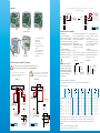 3
3
-
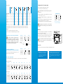 4
4
-
 5
5
-
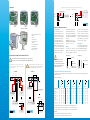 6
6
-
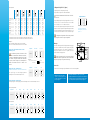 7
7
-
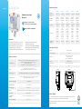 8
8
-
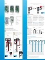 9
9
-
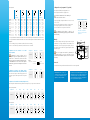 10
10
-
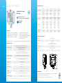 11
11
-
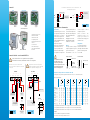 12
12
-
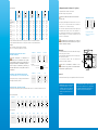 13
13
-
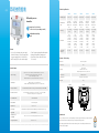 14
14
-
 15
15
-
 16
16
-
 17
17


sauermann CP 115 Guide de démarrage rapide
- Taper
- Guide de démarrage rapide
dans d''autres langues
- italiano: sauermann CP 115 Guida Rapida
- español: sauermann CP 115 Guía de inicio rápido
Documents connexes
-
sauermann CP 116 Guide de démarrage rapide
-
sauermann KIMO CP 116 Mode d'emploi
-
-
-
-
-
sauermann TH 110 Mode d'emploi
-
-
sauermann CTV 110 Mode d'emploi
-
Autres documents
-
 UEi DPA1 Le manuel du propriétaire
-
YOKOGAWA MT300 Getting Started Manual
-
 Thommen HM30 Operating Instructions Manual
-
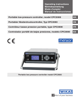 mensor Mensor CPC2000 Mode d'emploi
-
Vaisala PTB330 Manuel utilisateur
-
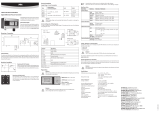 Rotronic PF4 Short Instruction Manual
-
WIKA CPC6050 Mode d'emploi
-
-
Eurotherm 3200 Mode d'emploi
-
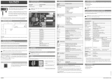 Rotronic PF4/PF5 Manuel utilisateur


