
12.0839.0002
ROTRONIC AG, CH-8303 Bassersdorf
Tel. +41 44 838 11 44, www.rotronic-humidity.com
ROTRONIC Messgeräte GmbH, D-76275 Ettlingen
Tel. +49 7243 383 250, Fax +49 7243 383 260, www.rotronic.de
ROTRONIC SARL, 56, F - 77183 Croissy Beaubourg
Tél. +33 1 60 95 07 10, www.rotronic.fr
ROTRONIC Italia srl
, I- 20157 Milano
Tel. +39 2 39 00 71 90, Fax (+39) 02 33 27 62 99, www.rotronic.it
ROTRONIC Instruments (UK) Ltd, Crompton Fields,
Phone +44 1293 571000, www.rotronic.co.uk
ROTRONIC Instrument Corp, NY 11788, USA
Phone +1 631 427-3898, www.rotronic-usa.com
ROTRONIC South East Asia Pte Ltd, Singapore 339156
Phone +65 6294 6065, www.rotronic.com.sg
ROTRONIC Shanghai Rep. Offi ce, Shanghai 200233, China
Phone +86 40 08162018, www.rotronic.cn
A
Digital transmitter for temperature
Congratulations on your purchase of the new state-of-the-art HYGRO-
FLEX TF5 SERIES transmitter. Please read these short instructions
carefully before installing the device.
General description
The HYGROFLEX5 SERIES devices are transmitters for transmission of
temperature measurements. Compatible with PT100 probes. These
short instructions are limited to a description of the main functions
and installation of the device. The detailed instruction manual can be
found on the internet at: www.rotronic-humidity.com
Mechanical installation
General recommendations
Follow the guidelines below to ensure optimum performance:
a) Select a representative installation site: Install the probe at a point where the temperature are
representative for the environment that is to be measured.
b) Make sure there is suffi cient air movement around the probe: An air fl ow of at least 1 metre/
second accelerates and facilitates adjustment of the probe to changing temperatures.
c) Avoid:
(1) Probe too close to heating elements, cooling coils, cold or hot walls, direct sunlight, etc.
(2) Probe too close to steam, injectors, humidifi ers or direct precipitation.
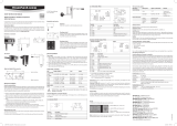
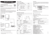
Mounting the wall version
Alignment
Mount the transmitter so that the probe points down.
Mounting variant 1
Drill the necessary holes using the drill template drawn on the
packaging. Then insert the plugs delivered with the device and
mount the transmitter with the screws.
Mounting variant 2
If there is a TS35 DIN top-hat rail available, the transmitter can be
clipped on to the top-hat rail directly with the help of the mounting
kit AC5002 (available as optional extra). For this, the DIN holders
(a kit has two holders and eight screws) are screwed directly on to
the predrilled holes in the transmitter.
Note: Unauthorised use of the menu can be prevented by locking the setting “Display Menu”
(using the HW4 software > Device Manager > Display).
The main menu points
Main menu Menu points Options / Information
Decive Settings
Units Metric / English
Record On / Off
Back Light On / Off
Device Information
Version Firmware version
Serial No. Serial number
Address Address RS-485
Type Device type
Name Device name User-defi ned
Scaling / Adjustment / Firmware update
The following settings can be made with the help of the HW4 software and either the service cable
AC3006 or AC3009:
• new scaling of the outputs
• adjustment
• fi rmware update
You can fi nd a detailed description in the manual that you can download from our web site at
www.rotronic-humidity.com
Periodic calibration of the probe / transmitter
Both the Pt 100 RTD temperature sensor and the corresponding electronics are very stable and
do not normally need to be changed or calibrated after factory calibration.
The electronics of the transmitter do not normally require calibration in the fi eld. They can be
checked easily with the help of the probe simulator in the HW4 software package. The electro-
nics cannot be repaired in the fi eld and should be returned to the manufacturer in the case
of problems. For details on calibration, please see the full version of the instruction manual,
which you can download from the internet.
Technical data (measurement)
Temperature: –100...200 °C
Accuracy: Probe-dependent
Protection: IP65
Outputs: Current or voltage signals, digital output depending on order code,
UART service interface
Technical data (operation)
Temperature: –40...60 °C / Models with display –10...60 °C
Technical data probe
Depending on type
Current output
Voltage output
SHORT INSTRUCTION MANUAL
T – OUT
V +
H – OUT
V +
K 2
K 1
2
1
2
1
1
2
3
K 1
GND
V +
K 2
GND
GND
OUT2
OUT1
4
3
2
1
OUT 1 = %rF
OUT 2 = °C/F
HYGROFLEX TF52 / TF53 SERIES
Electrical installation
Power supply
a) TF52 (2-wire, current loop): 10 to 28 VDC – depending on the connected load.
The minimum supply voltage can be calculated as follows. V min = 10 V + (0.02 x load*)
*Load (resistance in Ohm). The minimum supply voltage for the maximum load of 500 Ohm is:
10 + (0.02 x 500) = 20 VDC. The maximum current consumption is 30 mA.
b) TF53 (3-wire with analogue outputs): 5 to 40 VDC or 5 to 28 VAC. The maximum current con-
sumption is 30 mA.
Supply voltage / Technology
Type Supply voltage V+ Load Output
2- or 2x2-wire
TF520 10...28 VDC: 10 V + (0.02 x load) Max 500 Ω 4...20 mA
3 / 4 wire
TF531 15...40 VDC / 12...28 VAC Max 500 Ω 0...20 mA
TF532 15...40 VDC / 12...28 VAC Max 500 Ω 4...20 mA
TF533 5...40 VDC / 5...28 VAC Min 1000 Ω 0...1 V
TF534 10...40 VDC / 8...28 VAC Min 1000 Ω 0...5 V
TF535 15...40 VDC / 12...28 VAC Min 1000 Ω 0...10 V
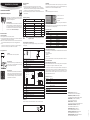
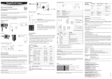
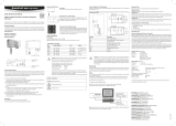
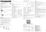
Terminal confi guration / Connection diagrams
The type is defi ned using the table Supply voltage / Technology to then use the following con-
nection diagrams:
2- oder 2x2 wire / TF520
Terminal Description
K2-2-T-OUT Analogue temperature output +
K2-1-V+ Supply voltage +
K1-2-H-OUT Not connected
K1-1-V+ Not connected
3/4-wire circuit / TF53x
Terminal Description
K1-1 GND GND / Neutral
K1-2 V+ Supply voltage + / Phase
K1-3 Earth
K2-4 GND GND
K2-3 GND GND
K2-2 OUT2 Analogue temperature output +
K2-1 OUT1 Not connected
=
~
K2: V+
K2: GND
K1: GND
K1: OUT2
Terminal K1-3:
Earth is not usually connected to GND. If this is wanted, a land on the PCB must be closed.
4 wire PT100
Programming
The basic settings of the devices are made in the factory according to your order. The transmit-
ters are adjusted in the factory and therefore do not need to be checked and readjusted during
installation. The devices can be started immediately after installation.
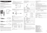
Display
In models with LC display the value can be read directly.
Caution: Wrong supply voltages and excessively high loading of the outputs can
damage the transmitter.
Button MENU: open / close menu
Button ENTER: select menu point
Menu navigation
Buttons + / - change value: increase/decrease

12.0839.0002
ROTRONIC AG, CH-8303 Bassersdorf
Tel. +41 44 838 11 44, www.rotronic-humidity.com
ROTRONIC Messgeräte GmbH, D-76275 Ettlingen
Tel. +49 7243 383 250, Fax +49 7243 383 260, www.rotronic.de
ROTRONIC SARL, 56, F - 77183 Croissy Beaubourg
Tél. +33 1 60 95 07 10, www.rotronic.fr
ROTRONIC Italia srl
, I- 20157 Milano
Tel. +39 2 39 00 71 90, Fax (+39) 02 33 27 62 99, www.rotronic.it
ROTRONIC Instruments (UK) Ltd, Crompton Fields,
Phone +44 1293 571000, www.rotronic.co.uk
ROTRONIC Instrument Corp, NY 11788, USA
Phone +1 631 427-3898, www.rotronic-usa.com
ROTRONIC South East Asia Pte Ltd, Singapore 339156
Phone +65 6294 6065, www.rotronic.com.sg
ROTRONIC Shanghai Rep. Offi ce, Shanghai 200233, China
Phone +86 40 08162018, www.rotronic.cn
Digitaler Messumformer für Temperatur
Wir beglückwünschen Sie zum Kauf Ihres neuen HYGROFLEX TF-SERIE
Messumformers. Sie haben damit ein dem neuesten Stand der Technik
entsprechendes Gerät erworben. Bitte lesen Sie diese
Kurz-Anleitung genau durch, bevor Sie das Gerät installieren.
Allgemeine Beschreibung
Die HYGROFLEX TF-SERIE Geräte sind Temperatur Messumformer, mit
auswechselbaren PT-100 Fühler. Diese Kurzbedienungsanleitung be-
schränkt sich auf die Beschreibung der wichtigsten Funktionen und der
Installation des Gerätes Die detaillierte Bedienungsanleitung fi nden
Sie im Internet unter: www.rotronic-humidity.com
Mechanische Installation
Allgemeine Empfehlungen
Einhaltung der folgenden Richtlinien garantiert Ihnen eine optimale Leistung des Gerätes:
a) Wählen Sie einen repräsentativen Installationsort: installieren Sie den Fühler an einem Ort,
wo die Temperatur für die zu messende Umgebung repräsentativ ist.
b) Stellen Sie genügend Luftbewegung am Fühler sicher: Eine Luftgeschwindigkeit von mindestens
1 Meter/Sekunde beschleunigt und erleichtert die Anpassung des Fühlers an wechselnde
Temperaturen.
c) Zu vermeiden sind:
(1) Fühler zu nahe an Heizelement, Kühlschlange, kalter oder warmer Wand, direkte Sonnen-
einstrahlung etc.
(2) Fühler zu nahe an Dampf- Injektor, Befeuchter, oder direkter Niederschlag.
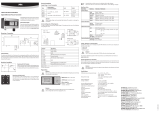
Montage der Wandversion
Ausrichtung
Der Transmitter wird so montiert, dass der Fühler
nach unten gerichtet ist.
Montage Variante 1
Mit der auf der Verpackung aufgezeichneten Bohrschablone werden
die nötigen Löcher gebohrt. Danach werden die mitgelieferten
Dübel eingesetzt um dann den Transmitter mit Hilfe der Schrauben
zu montieren.
Montage Variante 2
Bei vorhanden DIN-Hutschienen TS35 kann unter Mithilfe des
Montagekit AC5002 (optional erhältlich) der Transmitter direkt
auf die DIN Hutschienen aufgeschnappt werden. Hierzu werden
die DIN-Halterungen (Eine Verpackungseinheit besteht aus 2
Halterungen und 8 Schrauben) direkt auf die vorgebohrten Löcher
des Transmitters geschraubt.
Taste MENU: Menü öffnen / schliessen
Taste ENTER: Auswahl Menüpunkt
Menünavigation
Tasten + / - Wert ändern: Erhöhen / Verringern
Hinweis: Der unbefugte Zugriff auf das Menü kann durch Sperren der Einstellung “Display Menü”
verhindert werden (Verwendung der HW4-Software > Geräte-Manager > Display).
Die wichtigsten Menüpunkte.
Hauptmenü Menü-Punkte Auswahl / Information Hinweise
Decive Settings (Geräteeinstellungen)
Units (Einheiten) Metrisch / Englisch
Aufzeichnung Ein / Aus
Hintergrundbeleuchtung Ein / Aus
Device Information (Geräte-Informationen)
Version (Version) Firmwareversion
Serial Nbr (Seriennr.) Seriennummer
Address (Adresse) Adresse RS-485
Type (Typ) Gerätetyp
Name (Bezeichnung) Gerätename Benutzerdefi niert
Skalierung / Justierung / Firmware update
Mit Hilfe der HW4 Software und dem Servicekabel AC3006 können folgende Einstellungen
durchgeführt werden:
• Neuskalierung der Ausgänge
• Justierung
• Firmware update
Eine detaillierte Beschreibung fi nden Sie im Manual welches Sie im Internet unter:
www.rotronic-humidity.com herunterladen können.
Periodische Kalibrierung des Fühlers / Transmitters
Sowohl der Pt 100 RTD Temperatursensor als auch die dazugehörende Elektronik sind sehr stabil
und müssen nach der Werkskalibrierung normalerweise nicht verändert oder kalibriert werden.
Für eine maximale Genauigkeit empfehlen wir eine Kalibrierung der Fühler ca. alle sechs bis
12 Monate.
Die Elektronik des Messumformers selber erfordert normalerweise keine Kalibrierung im Feld.
Die Elektronik lässt sich nicht im Feld reparieren und sollte bei Problemen ans Herstellerwerk
retourniert werden.
Technische Daten (Messbereich)
Temperatur: –100...200 °C
Genauigkeit: Fühlerabhängig
Schutzart: IP65
Ausgänge: Strom- oder Spannungssignal, digitaler Ausgang je nach Bestellcode,
UART Service Schnittstelle
Technische Daten (Einsaztbereich)
Temperatur: –40...60 °C / Modelle mit Anzeige –10...60 °C
Technische Daten Fühler
Je nach Typ
Stromausgang
Spannungsausgang
KURZBEDIENUNGSANLEITUNG
T – OUT
V +
H – OUT
V +
K 2
K 1
2
1
2
1
1
2
3
K 1
GND
V +
K 2
GND
GND
OUT2
OUT1
4
3
2
1
OUT 1 = %rF
OUT 2 = °C/F
HYGROFLEX TF52 / TF53-SERIE
Elektrische Installation
Stromversorgung
a) TF52 (2-Leiter, Stromschleife): 10 bis 28 VDC – Abhängig von der angeschlossenen Last. Die
minimale Spannungsversorgung kann wie folgt berechnet werden. V min = 10 V + (0.02 x
Bürde*)
*Bürde (Widerstand in Ohm). Für die maximum Last von 500 Ohm, ist die minimale Spannung:
10 + (0.02 x 500) = 20 VDC. Die maximale Stromaufnahme beträgt 30mA.
b) TF53 (3-Leiter mit Analogausgängen): 5 bis 40 VDC oder 5 bis 28 VAC. Mit beiden. Die maximale
Stromaufnahme beträgt 30mA.
Versorgungsspannung / Typ
Typ Spannungsversorgung Last Ausgang
2- oder 2x2 Leiter
TF520 10...28 VDC: 10 V + (0.02 x load) Max 500 Ω 4...20 mA
3 / 4 Leiter
TF531 15...40 VDC / 12...28 VAC Max 500 Ω 0...20 mA
TF532 15...40 VDC / 12...28 VAC Max 500 Ω 4...20 mA
TF533 5...40 VDC / 5...28 VAC Min 1000 Ω 0...1 V
TF534 10...40 VDC / 8...28 VAC Min 1000 Ω 0...5 V
TF535 15...40 VDC / 12...28 VAC Min 1000 Ω 0...10 V
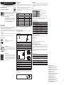
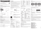
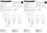
Klemmenbelegung / Anschlussschemata
Anhand der Tabelle Versorgungsspannung / Technologie wird der Typ defi niert, um folgende
Anschluss-Schemas verwenden zu können:
2- oder 2x2 Leiter / TF520
Klemme Beschreibung
K2-2-T-OUT Temperatur-Analogausgang +
K2-1-V+ Spannungsversorgung +
K1-2-H-OUT Nicht angeschlossen
K1-1-V+ Nicht angeschlossen
3/4 Leiter Schaltung / HF53x
Klemme Beschreibung
K1-1 GND GND / Neutral
K1-2 V+ Spannungsversorgung+ / Phase
K1-3 Erde
K2-4 GND GND
K2-3 GND GND
K2-2 OUT2 Temperatur-Analogausgang +
K2-1 OUT1 Nicht angeschlossen
=
~
K2: V+
K2: GND
K1: GND
K1: OUT2
Klemme K1-3:
Erde ist standardmässig nicht mit GND verbunden. Wird das gewünscht, muss auf dem PCB ein
Lötauge geschlossen werden.
4 Draht PT100
Programmierung
Die Grundeinstellungen der Geräte werden im Werk, gemäss Ihrer Bestellung, vorgenommen.
Die Transmitter werden im Werk justiert, sodass eine Überprüfung oder Nachjustierung bei
der Installation nicht notwendig ist. Die Geräte können sofort nach der Installation in Betrieb
genommen werden.
Display
Bei Modellen mit LC-Display, kann der Wert direkt abgelesen werden.
A
Achtung: Falsche Versorgungsspannungen sowie zu grosse Belastungen der
Ausgänge können den Messumformer beschädigen.

12.0839.0002
ROTRONIC AG, CH-8303 Bassersdorf
Tel. +41 44 838 11 44, www.rotronic-humidity.com
ROTRONIC Messgeräte GmbH, D-76275 Ettlingen
Tel. +49 7243 383 250, Fax +49 7243 383 260, www.rotronic.de
ROTRONIC SARL, 56, F - 77183 Croissy Beaubourg
Tél. +33 1 60 95 07 10, www.rotronic.fr
ROTRONIC Italia srl
, I- 20157 Milano
Tel. +39 2 39 00 71 90, Fax (+39) 02 33 27 62 99, www.rotronic.it
ROTRONIC Instruments (UK) Ltd, Crompton Fields,
Phone +44 1293 571000, www.rotronic.co.uk
ROTRONIC Instrument Corp, NY 11788, USA
Phone +1 631 427-3898, www.rotronic-usa.com
ROTRONIC South East Asia Pte Ltd, Singapore 339156
Phone +65 6294 6065, www.rotronic.com.sg
ROTRONIC Shanghai Rep. Offi ce, Shanghai 200233, China
Phone +86 40 08162018, www.rotronic.cn
Transmetteur de mesure numérique pour température.
Tous nos remerciements pour l’achat de votre nouveau transmetteur
de mesures de la série HYGROFLEX TF. Vous avez fait l’acquisition d’un
appareil doté de la technologie la plus récente. Veuillez lire attentive-
ment ce manuel abrégé avant d’installer l’appareil.
Description générale
Les appareils de la série HYGROFLEX TF sont des transmetteurs
de mesures de température, équipés de capteurs PT-100 inter-
changeables. Ce mode d’emploi abrégé se limite à la description
des fonctions essentielles et à l’installation de cet appareil. Vous
trouverez un manuel d’utilisation détaillé sur notre site Internet:
www.rotronic-humidity.com
Installation mécanique
Recommandations générales
Le respect des directives suivantes vous garantit des performances optimales de l’appareil :
a) Choisissez un site d’installation correct: installez le capteur à un endroit où la température est
représentative de l’environnement à mesurer.
b) Assurez un mouvement d’air suffi sant autour du capteur : une vitesse d’air d’au moins 1 mètre/
seconde accélère et facilite l’adaptation du capteur aux changements de température.
c) À éviter :
1. Capteur trop près d’éléments de chauffage, serpentins de refroidissement, mur froid ou
chaud, exposition directe aux rayons solaires, etc.
2. Capteur trop proche de vapeur, d’un injecteur, d’un humidifi cateur ou exposé à des préci-
pitations directes.
Montage de la version murale
Orientation
Le transmetteur est monté de façon à ce que
le capteur soit dirigé vers le bas.
Variante de montage 1
Les perforations nécessaires sont effectuées à l’aide du gabarit
de perçage imprimé sur l’emballage. Ensuite, mettre en place
les chevilles fournies pour monter le transmetteur de mesure à
l’aide des vis.
Variante de montage 2
Si des embases de rail DIN TS35 sont déjà en place, il est possible
de clipser directement le transmetteur sur les embases de rail DIN
à l’aide du kit de montage AC5002 (disponible en option). Pour
cela, visser les fi xations DIN (une unité d’emballage se compose
de 2 fi xations et 8 vis) directement sur les trous pré-percés du
transmetteur de mesure.
Touche MENU : ouvrir / fermer le menu
Touche ENTER : Sélection élément de menu
Navigation dans le menu
Touches + / - Modifi er valeur:
Augmenter / réduire
Remarque: l’accès non autorisé au menu peut être empêché en bloquant le réglage « Menu
affi cheur » (utilisation du logiciel HW4 > Gestionnaire d’appareils > Affi cheur).
Les principaux éléments du menu.
Menu principal Éléments de menu Sélection / information Remarques
Device Settings (réglages d’appareils)
Units (unités) Métrique / anglais
Enregistrement Marche / Arrêt
Rétro éclairage Marche / Arrêt
Device Information (informations sur l’appareil)
Version (Version) Version du logiciel résident
Serial Nbr (n° série) Numéro de série
Address (Adresse) Adresse RS-485
Type (Typ) Type d’appareil
Name (Désignation) Nom d’appareil Défi ni par l’utilisateur
Changement d’échelle / ajustage / mise à jour du logiciel résident
Le logiciel HW4 et le câble de service AC3006 ou AC3009 permettent de réaliser les réglages
suivants:
• Changement d’échelle des sorties
• Ajustage
• Mise à jour du logiciel résident
Vous trouverez une description détaillée dans le manuel que vous pouvez télécharger sous
www.rotronic-humidity.com
Étalonnage périodique du capteur / transmetteur de mesure
L’élément sensible de température Pt 100 RTD ainsi que l’électronique correspondante sont très
stables et ne doivent normalement pas être modifi és ou ajustés après leur étalonnage en usine.
Nous conseillons, pour une précision maximale, un intervalle d’étalonnage pour les capteurs
de six à douze mois.
L’électronique du transmetteur de mesures ne nécessite pas d’étalonnage sur place. Elle ne peut
pas être réparée sur site et doit être retournée au fabricant en cas de problème.
Caractéristiques techniques (Gamme de mesure)
Température: –100...200 °C
Précision: selon le capteur
Type de protection: IP65
Sorties: Signal de courant ou de tension, sortie numérique selon le code
de commande, interface de service UART
Caractéristiques techniques (gamme d’utilisation)
Température: –40...60 °C / Modèles avec affi chage –10...60 °C
Caractéristiques techniques capteur
Selon le type
Sortie courant
Sortie tension
MODE D'EMPLOI ABRÉGÉ
T – OUT
V +
H – OUT
V +
K 2
K 1
2
1
2
1
1
2
3
K 1
GND
V +
K 2
GND
GND
OUT2
OUT1
4
3
2
1
OUT 1 = %HR
OUT 2 = °C/F
SÉRIES HYGROFLEX TF52 / TF53
Installation électrique
Alimentation électrique
a) TF52 (2 conducteurs, boucle de courant): 10 à 28 VCC – selon la charge raccordée. La tension
d’alimentation minimale peut être calculée comme suit: V min = 10 V + (0,02 x charge*)
*Charge (résistance en Ohm). Pour une charge maximale de 500Ohm, la tension minimale est
de: 10 + (0,02 x 500) = 20 VCC. La consommation maximale en courant est de 30mA.
b) TF53 (3 conducteurs avec sorties analogiques): 5 à 40 VCC ou 5 à 28 VCA. Avec les deux, la
consommation maximale de courant est de 30mA.
Tension d’alimentation / Type
Type Tension d’alimentation Charge Sortie
2 ou 2x2 conducteurs
TF520 10...28 VCC: 10 V + (0,02 x charge) Max 500 Ω 4...20 mA
3 / 4 conducteurs
TF531 15...40 VCC / 12...28 VCA Max 500 Ω 0...20 mA
TF532 15...40 VCC / 12...28 VCA Max 500 Ω 4...20 mA
TF533 5...40 VCC /5...28 VCA Min 1000 Ω 0...1 V
TF534 10...40 VCC / 8...28 VCA Min 1000 Ω 0...5 V
TF535 15...40 VCC / 12...28 VCA Min 1000 Ω 0...10 V
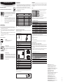
Affectation des bornes / schémas de raccordement
Le tableau de tension d’alimentation / technologie sert à défi nir le type pour pouvoir utiliser les
schémas de raccordement suivants:
2- ou 2x2 conducteurs / TF520
Borne Description
K2-2-T-OUT Sortie analogique de température +
K2-1-V+ Alimentation en tension +
K1-2-H-OUT Non raccordé
K1-1-V+ Non raccordé
Branchement 3 / 4 conducteurs / HF53x
Borne Description
K1-1 GND GND / neutre
K1-2 V+ Alimentation en tension +/Phase
K1-3 Terre
K2-4 GND GND
K2-3 GND GND
K2-2 OUT2 Sortie analogique de température +
K2-1 OUT1 Non raccordé
=
~
K2: V+
K2: GND
K1: GND
K1: OUT2
Borne K1-3:
La terre n’est pas raccordé en standard à la borne GND. Si cela est souhaité, il faut fermer un orifi ce
de soudure sur le circuit imprimé.
4 conducteurs PT100
Programmation
Les réglages de base des appareils sont effectués en usine conformément à votre commande.
Les transmetteurs de mesure sont ajustés en usine. De ce fait, une vérifi cation ou réajustement
de l’installation n’est pas nécessaire. Les appareils peuvent être mis en service immédiatement
après l’installation.
Display
Sur les modèles dotés d’un affi cheur à cristaux liquides, la valeur peut être relevée directement.
A
Attention: des tensions d’alimentation incorrectes ainsi que des sollicitations trop
fortes des sorties peuvent endommager le transmetteur de mesure.

12.0839.0002
ROTRONIC AG, CH-8303 Bassersdorf
Tel. +41 44 838 11 44, www.rotronic-humidity.com
ROTRONIC Messgeräte GmbH, D-76275 Ettlingen
Tel. +49 7243 383 250, Fax +49 7243 383 260, www.rotronic.de
ROTRONIC SARL, 56, F - 77183 Croissy Beaubourg
Tél. +33 1 60 95 07 10, www.rotronic.fr
ROTRONIC Italia srl
, I- 20157 Milano
Tel. +39 2 39 00 71 90, Fax (+39) 02 33 27 62 99, www.rotronic.it
ROTRONIC Instruments (UK) Ltd, Crompton Fields,
Phone +44 1293 571000, www.rotronic.co.uk
ROTRONIC Instrument Corp, NY 11788, USA
Phone +1 631 427-3898, www.rotronic-usa.com
ROTRONIC South East Asia Pte Ltd, Singapore 339156
Phone +65 6294 6065, www.rotronic.com.sg
ROTRONIC Shanghai Rep. Offi ce, Shanghai 200233, China
Phone +86 40 08162018, www.rotronic.cn
Trasduttori digitali per temperatura
Ci congratuliamo per il vostro acquisto di un nuovo trasmettitore della
SERIE HYGROFLEX TF. Avete acquistato uno strumento al passo con le
tecnologie più moderne. Vi preghiamo di leggere la presente guida
rapida con attenzione, prima di installare lo strumento.
Informazioni generali
Gli apparecchi della SERIE HYGROFLEX TF sono trasmettitori di tempe-
ratura, con sonde PT-100 intercambiabili. La presente guida rapida
si limita a descrivere le funzioni principali dello strumento e la sua
installazione. Le istruzioni d’uso dettagliate sono disponibili in Internet
all’indirizzo: www.rotronic-humidity.com
Installazione meccanica
Consigli generici
Il rispetto delle prescrizioni di seguito riportate garantisce un rendimento ottimale dell’apparecchio:
a) Selezionare una sede di installazione rappresentativa per le misurazioni: installare la sonda
in un punto in cui le condizioni di temperatura siano rappresentative per l’ambiente che si
intende misurare.
b) Garantire che la sonda sia sottoposta a suffi ciente ventilazione: una velocità dell’aria di almeno
1 metro/secondo accelera e facilita l'adattamento della sonda alle oscillazioni di temperatura.
c) Condizioni da evitare:
(1) Sonda troppo vicina a elementi riscaldanti, serpentine di raffreddamento, pareti fredde
o calde, esposizione diretta ai raggi solari ecc.
(2) Sonda troppo vicina a generatori di vapore, iniettori, umidifi catori o precipitazioni dirette.
Montaggio della versione a parete
Orientamento
Il trasmettitore va montato in modo che la sonda
sia rivolta verso il basso.
Variante 1 di montaggio
Utilizzando la sagoma di foratura raffi gurata sulla confezione si
effettuano i fori necessari. In seguito si inseriscono i tasselli in
dotazione per poi montare il trasmettitore con l'ausilio delle viti.
Variante 2 di montaggio
Se sono presenti le barre di montaggio DIN TS35, utilizzando il kit
di montaggio AC5002 (opzionale) è possibile montare a scatto il
trasmettitore direttamente sulle barre DIN. A tal scopo si avvitano
direttamente sui fori prestampigliati del trasmettitore i supporti
DIN (una confezione contiene 2 supporti e 8 viti).
Tasto MENU: si apre / si chiude il menu
Tasto ENTER: selezione della voce di menu
Navigazione nel menu
Tasti + / - per la modifi ca valore:
aumento / diminuzione
Nota: è possibile evitare un accesso non autorizzato al menu bloccando l’opzione “Display
Menu” (se si utilizza il software HW4 > Device Manager (Manager strumenti) > Display).
Le principali opzioni di menu
Menu principale Voci del menu Selezione/Informazione Note
Device Settings (Impostazioni apparecchio)
Units (unità) Metrico / inglese
Record (Acquisizione) On / Off
Retroilluminazione On / Off
Device Information (Informazioni apparecchio)
Version (Versione) Versione Firmware
Serial Nbr (N° di serie) Numero di serie
Address (Indirizzo) Indirizzo RS-485
Type (Tipo) Tipo di apparecchio
Name (Denominazione) Nome dell’apparecchio Defi nito dall’utente
Scalabilità / Ricalibrazione / Firmware update
Grazie al software HW4 e al cavo di servizio AC3006 si possono effettuare le seguenti impostazioni:
• Uscite riscalabili
• Ricalibrazione
• Firmware update
Una descrizione dettagliata è riportata nel manuale scaricabile all’indirizzo Internet:
www.rotronic-humidity.com
Calibrazione periodica della sonda / del trasmettitore
Sia il sensore per la temperatura Pt 100 RTD sia i relativi dispositivi elettronici sono estremamente
stabili e di solito non vanno più modifi cati o calibrati dopo la calibrazione effettuata di fabbrica.
Per ottenere la massima precisione possibile, consigliamo di effettuare una calibrazione delle
sonde ogni sei – dodici mesi.
Gli stessi dispositivi elettronici del trasmettitore non necessitano normalmente di una calibrazione
on site, né sono ivi riparabili per cui, in caso di problemi, gli strumenti dovrebbero essere inviati
allo stabilimento di fabbricazione.
Dati tecnici (range di misurazione)
Temperatura: –100...200 °C
Precisione: in funzione della sonda
Classe di protezione: IP65
Uscite: segnale di corrente o di tensione, uscita digitale in base al codice
d’ordine, interfaccia di servizio UART
Dati tecnici (range di utilizzo)
Temperatura: –40...60 °C / modelli con display –10...60 °C
Dati tecnici sonda
In base al tipo
Uscita di corrente
Uscita di tensione
MANUALE D'ISTRUZIONI BREVE
T – OUT
V +
H – OUT
V +
K 2
K 1
2
1
2
1
1
2
3
K 1
GND
V +
K 2
GND
GND
OUT2
OUT1
4
3
2
1
OUT 1 = %UR
OUT 2 = °C/F
SERIE HYGROFLEX TF52 / TF53
Installazione elettrica
Alimentazione di corrente
a) TF52 (versione a 2 fi li, loop di corrente): da 10 a 28 VDC – in funzione del carico collegato.
L'alimentazione di tensione minima è calcolabile secondo la formula seguente. V min = 10 V
+ (0,02 x carico*)
*Carico (resistenza in Ohm). Per il carico massimo di 500 Ohm, la tensione minima risulta: 10
+ (0,02 x 500) = 20 VDC. L’assorbimento di corrente massimo corrisponde a 30mA.
b) TF53 (versione a 3 fi li con uscite analogiche): da 5 a 40 VDC oppure da 5 a 28 VAC. L'assorbi-
mento massimo di corrente corrisponde a 30mA in entrambi i casi.
Tensione di alimentazione / tipo
Tipo Alimentazione di tensione Carico Uscita
Versione 2 o 2x2 fi li
TF520 10...28 VDC: 10 V + (0,02 x carico) Max 500 Ω 4...20 mA
3/4 fi li
TF531 15...40 VDC / 12...28 VAC Max 500 Ω 0...20 mA
TF532 15...40 VDC / 12...28 VAC Max 500 Ω 4...20 mA
TF533 5...40 VDC / 5...28 VAC Min 1000 Ω 0...1 V
TF534 10...40 VDC / 8...28 VAC Min 1000 Ω 0...5 V
TF535 15...40 VDC / 12...28 VAC Min 1000 Ω 0...10 V
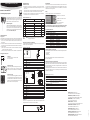
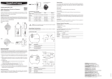
Disposizione dei morsetti / schemi di collegamento
In base alla tabella Tensione di alimentazione / tecnologia si defi nisce il tipo, per poter quindi
utilizzare i seguenti schemi di collegamento:
Versione a 2 o 2x2 fi li / TF520
Morsetto Descrizione
K2-2-T-OUT Uscita analogica temperatura +
K2-1-V+ Alimentazione di tensione +
K1-2-H-OUT Non collegato
K1-1-V+ Non collegato
Versione con circuito a 3 / 4 fi li / HF53x
Morsetto Descrizione
K1-1 GND GND / Neutro
K1-2 V+ Alimentazione di tensione+ / Fase
K1-3 Terra
K2-4 GND GND
K2-3 GND GND
K2-2 OUT2 Uscita analogica temperatura +
K2-1 OUT1 Non collegato
=
~
K2: V+
K2: GND
K1: GND
K1: OUT2
Morsetto K1-3:
La terra non ha un collegamento standard con il GND. Se è richiesto tale collegamento, si deve
collegare alla scheda di circuito stampata un occhiello di saldatura.
PT100 a 4 fi li
Programmazione
Le impostazioni base dello strumento sono effettuate di fabbrica, in accordo alla Vostra ordina-
zione. I trasmettitori sono regolati di fabbrica e pertanto in fase di installazione non è necessario
effettuare un controllo o una ricalibrazione. Pertanto dopo l’installazione è possibile mettere
immediatamente in funzione gli strumenti.
Display
I modelli con display LCD permettono la lettura immediata del valore.
A
Attenzione: tensioni di alimentazione errate o carichi eccessivi sulle uscite possono
danneggiare il trasmettitore.
-
 1
1
-
 2
2
-
 3
3
-
 4
4


dans d''autres langues
- italiano: Rotronic TF5
- English: Rotronic TF5
- Deutsch: Rotronic TF5
Documents connexes
-
 Rotronic HF4 Manuel utilisateur
-
 Rotronic hf5 Manuel utilisateur
-
 Rotronic XB OEM Short Instruction Manual
-
 Rotronic hf3 Short Instruction Manual
-
 Rotronic hf3 Manuel utilisateur
-
 Rotronic HF5NEW Manuel utilisateur
-
 Rotronic PF4 Short Instruction Manual
-
 Rotronic HF8 Short Instruction Manual
-
 Rotronic HF5NEW Manuel utilisateur
-
 Rotronic AC3011 Masterbox Short Instruction Manual


