KitchenAid KVUB400GSS00 Le manuel du propriétaire
- Catégorie
- Hottes
- Taper
- Le manuel du propriétaire
Ce manuel convient également à

30" AND 36" (76.2 AND 91.4 CM) RANGE HOOD
Installation Instructions and Use & Care Guide
HOTTE D’ASPIRATION DE 30" ET 36" (76,2ET91,4 CM)
Instructions d’installation et Guide d’utilisation et d’entretien
Table of Contents/Table des matières.............................................................................2
LIB0131212/W11088979A
IMPORTANT: READ AND SAVE THESE INSTRUCTIONS.
FOR RESIDENTIAL USE ONL
Y.
IMPOR
TANT : LIRE ET CONSERVER CES INSTRUCTIONS.
POUR UTILISA
TION RÉSIDENTIELLE UNIQUEMENT
.

2
TABLE OF CONTENTS TABLE DES MATIÈRES
RANGE HOOD SAFETY
RANGE HOOD SAFETY .................................................................2
INSTALLATION REQUIREMENTS .................................................4
Tools and Parts .............................................................................4
Location Requirements ................................................................4
Venting Requirements ..................................................................5
Electrical Requirements ...............................................................7
INSTALLATION INSTRUCTIONS ...................................................8
Prepare Location ..........................................................................8
Complete Preparation ................................................................10
Install Range Hood .....................................................................12
Connect the Vent System ..........................................................13
Complete Installation .................................................................13
RANGE HOOD USE ......................................................................14
Range Hood Controls ................................................................14
RANGE HOOD CARE ...................................................................15
Cleaning .....................................................................................15
WIRING DIAGRAM .......................................................................16
ASSISTANCE OR SERVICE .........................................................17
In the U.S.A. ...............................................................................17
In Canada ...................................................................................17
Accessories ................................................................................17
WARRANTY ..................................................................................18
SÉCURITÉ DE LA HOTTE DE CUISINIÈRE ...............................19
EXIGENCES D’INSTALLATION ...................................................21
Outils et pièces ...........................................................................21
Exigences d’emplacement .........................................................21
Exigences concernant l’évacuation ...........................................22
Spécications électriques ..........................................................24
INSTRUCTIONS D’INSTALLATION .............................................25
Préparation de l’emplacement ...................................................25
Préparation terminée ..................................................................27
Installation de la hotte ................................................................29
Raccordement du conduit d’évacuation ...................................30
Fin de l’installation ......................................................................30
UTILISATION DE LA HOTTE .......................................................31
Commandes de la hotte.............................................................31
ENTRETIEN DE LA HOTTE .........................................................32
Nettoyage ...................................................................................32
SCHÉMA DE CÂBLAGE ...............................................................33
ASSISTANCE OU SERVICE .........................................................34
Aux É.-U. ...................................................................................34
Au Canada ..................................................................................34
Accessoires ................................................................................34
GARANTIE LIMITÉEDES GROS APPAREILS MÉNAGERS
WHIRLPOOL
®
...............................................................................35

3
State of California Proposition 65 Warnings:
WARNING: This product contains one or more chemicals known to the State of California to cause cancer.
WARNING: This product contains one or more chemicals known to the State of California to cause birth defects or other
reproductive harm.
IMPORTANT SAFETY INSTRUCTIONS
READ AND SAVE THESE INSTRUCTIONS
WARNING: TO REDUCE THE RISK OF FIRE, ELECTRIC
SHOCK, OR INJURY TO PERSONS, OBSERVE THE
FOLLOWING:
■ Use this unit only in the manner intended by the
manufacturer. If you have questions, contact the
manufacturer.
■
Before servicing or cleaning the unit, switch power off at
service panel and lock the service disconnecting means to
prevent power from being switched on accidentally. When
the service disconnecting means cannot be locked,
securely fasten a prominent warning device, such as a tag,
to the service panel.
■ Installation work and electrical wiring must be done by
qualified person(s) in accordance with all applicable codes
and standards, including fire-rated construction.
■ Do not operate any fan with a damaged cord or plug.
Discard fan or return to an authorized service facility for
examination and/or repair.
■
Sufficient air is needed for proper combustion and
exhausting of gases through the flue (chimney) of fuel
burning equipment to prevent backdrafting. Follow the
heating equipment manufacturer's guideline and safety
standards such as those published by the National Fire
Protection Association (NFPA), the American Society for
Heating, Refrigeration and Air Conditioning Engineers
(ASHRAE), and the local code authorities.
■
When cutting or drilling into wall or ceiling; do not damage
electrical wiring and other utilities.
■ Ducted fans must always be vented outdoors.
CAUTION: For general ventilating use only. Do not use
to exhaust hazardous or explosive materials and vapors.
CAUTION:
To reduce risk of fire and to properly exhaust
air, be sure to duct air outside - do not vent exhaust air into
spaces within walls or ceilings, attics or into crawl spaces,
or garages.
WARNING:
TO REDUCE THE RISK OF FIRE, USE ONLY
METAL DUCTWORK.
WARNING:
TO REDUCE THE RISK OF A RANGE TOP
GREASE FIRE:
■ Never leave surface units unattended at high settings.
Boilovers cause smoking and greasy spillovers that may
ignite. Heat oils slowly on low or medium settings.
■
Always turn hood ON when cooking at high heat or when
flambeing food (i.e. Crepes Suzette, Cherries Jubilee,
Peppercorn Beef Flambé).
■ Clean ventilating fans frequently. Grease should not be
allowed to accumulate on fan or filter.
■
Use proper pan size. Always use cookware appropriate for
the size of the surface element.
WARNING: TO REDUCE THE RISK OF INJURY TO
PERSONS IN THE EVENT OF A RANGE TOP GREASE
FIRE, OBSERVE THE FOLLOWING:
a
■
SMOTHER FLAMES with a close fitting lid, cookie sheet, or
metal tray, then turn off the burner. BE CAREFUL TO
PREVENT BURNS. If the flames do not go out
immediately, EVACUATE AND CALL THE FIRE
DEPARTMENT.
■
NEVER PICK UP A FLAMING PAN - you may be burned.
■
DO NOT USE WATER, including wet dishcloths or towels -
a violent steam explosion will result.
■
Use an extinguisher ONLY if:
– You know you have a class ABC extinguisher, and you
already know how to operate it.
– The fire is small and contained in the area where it
started.
– The fire department is being called.
– You can fight the fire with your back to an exit.
a
Based on "Kitchen Fire Safety Tips" published by NFPA.
■ WARNING: To reduce the risk of fire or electrical shock,
do not use this fan with any solid-state speed control
device.

4
INSTALLATION REQUIREMENTS
Tools and Parts
Gather the required tools and parts before starting installation.
Read and follow the instructions provided with any tools listed
here.
Tools needed
■ Level
■ Drill with 1
1
/
4
" (3.2 cm), 1/8" (3 mm),
and 1/16" (1.6 mm) drill bits
■ Pencil
■ Wire stripper or utility knife
■ Pliers
■ Tape measure or ruler
■ Caulking gun and weatherproof caulking compound
■ Phillips screwdriver
■ Flat-blade screwdriver
■ Vent clamps
■ Jigsaw or keyhole saw
■ Metal snips
Parts needed
■ 6" (15.2 cm) round metal vent system
■ Vent clamps/duct tape as required
For non-vented (recirculating) installations, you will need:
■ Recirculation Kit. See the “Assistance or Service” section
to order.
For vented installations, you will need:
■ 1 wall or roof cap
Parts supplied
Remove parts from packages. Check that all parts are included.
■ Hood assembly with LED lights already installed (1)
■ Hood insert assembly with blower/electronic box
■ 4.5 x 13 mm truss-head wood screws (11)
■ 4.2 x 8 mm screws (8)
■ 4 x 15 mm screws (10)
■ 3.5 x 9.5 T10 (2)
■ Mounting brackets (4)
■ TORX
®†
adapter screws T10
®
and T20
®
adapter (1)
■ 6.4 x 18 mm washers (8)
■ 4.2 x 12 mm plastic washers (8)
■ 6" (15.2 cm) round damper (1)
Parts not supplied
Optional Accessories
For non-vented (Recirculating) installations:
1. Please see the "Assistance or Service" Section for the
recirculation kit part number information.
Location Requirements
IMPORTANT: Observe all governing codes and ordinances.
Have a qualied technician install the range hood. It is the
installer’s responsibility to comply with installation clearances
specied on the model/serial rating plate. The model/serial rating
plate is located inside the liner behind the lter on the left wall of
the range hood.
Range hood location should be away from strong draft areas,
such as windows, doors, and strong heating vents.
Cabinet opening dimensions that are shown must be used.
Given dimensions provide minimum clearance. Consult your
cooktop/range manufacturer installation instructions before
making any cutouts.
This range hood is recommended for use with cooktops with a
maximum total rating of 65,000 Btus or less.
Grounded electrical outlet is required. See the “Electrical
Requirements” section.
The range hood is factory set for vented installations through
the roof or wall. For non-vented (recirculating) installations
see “Non-Vented (recirculating) Installation Through the Soft/
Cabinet” in the “Prepare Location” section. Recirculation Kit is
available from your dealer or an authorized parts distributor. See
the “Assistance or Service” section to order.
All openings in ceiling and wall where range hood will be
installed must be sealed.
For Mobile Home Installations
The installation of this range hood must conform to the
Manufactured Home Construction Safety Standards, Title 24
CFR, Part 328 (formerly the Federal Standard for Mobile Home
Construction and Safety, title 24, HUD, Part 280) or when such
standard is not applicable, the standard for Manufactured Home
Installation 1982 (Manufactured Home Sites, Communities and
Setups) ANSI A225.1/NFPA 501A, or latest edition, or with local
codes.
†TORX
®
, T10
®
, and T20
®
are trademarks of Acument Intellectual Properties, Inc.

5
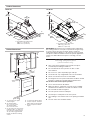
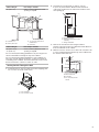
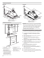
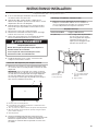
Product Dimensions
Cabinet Dimensions
A. 12" (30.5 cm) min. upper
cabinet height
B. 30" cabinet width:
min. 27.4" max 28.5"
36" cabinet width:
min. 33.9" max 34.5"
C. 24" (61.0 cm) min. from electric
cooking surface, 27" (68.6 cm)
min. from gas cooking surface,
36" (91.4 cm) suggested max.
bottom of cabinet to cooking
surface
D. 12" (30.5 cm) cabinet depth
E. 15" (38.1 cm) min. clearance
upper cabinet to countertop
F. 36" (91.4 cm) base cabinet
height
IMPORTANT: Mount this hood so that the bottom edge above
the cooking surface is at 27" (68.5 cm) minimum if a gas range
is used, or at 24" (61 cm) if an electric range is used. The
suggested maximum distance is 36" (91.4 cm). For household
use, please read the installation manual for specic application.
Check your cabinet dimensions prior to selecting your vent
hood.
Venting Requirements
(vented models only)
■ Vent system must terminate to the outside, except for
nonvented (recirculating) installations.
■ Do not terminate the vent system in an attic or other
enclosed area.
■ Do not use a 4" (10.2 cm) laundry-type wall cap.
■ Use metal vent only. A rigid metal vent is recommended.
■ Plastic or metal foil vent is not recommended.
■ The length of the vent system and number of elbows should
be kept to a minimum to provide efcient performance.
For the most efcient and quiet operation:
■ Use no more than three 90° elbows.
■ Make sure there is a minimum of 24" (61.0 cm) of straight
vent between the elbows if more than one elbow is used.
■ Do not install two elbows together.
■ The vent system must have a damper.
■ Use clamps to seal all joints in the vent system.
■ Use caulking to seal exterior wall or roof opening around the
cap.
■ The size of the vent should be uniform.
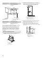
F
A
B
C
D
E
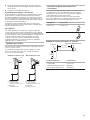
30" Model
6"
(15.2 cm)
1"
(2.5 cm)
10
3
/4"
(27.2 cm)
16
1
/2"
(42 cm)
11
1
/2"
(29.2 cm)
2
3
/8"
(6 cm)
19
11
/16"
(50 cm)
29
15
/16"
(76 cm)
26"
(66 cm)
A
A. 30" Cabinet inner dimensions
MIN: 27
15
⁄
32
" (69.75 cm)
MAX: 28
13
⁄
64
" (71.65 cm)
36" Model
1"
(2.5 cm)
10
3
/4"
(27.2 cm)
19
11
/16"
(50 cm)
35
15
/16"
(91.4 cm)
26"
(66 cm)
A
6"
(15.2 cm)
16
1
/2"
(42 cm)
11
1
/2"
(29.2 cm)
2
3
/8"
(6 cm)
A. 36" Cabinet inner dimensions
MIN: 33
15
⁄
32
" (86.2 cm)
MAX: 34
11
⁄
16
" (88.1 cm)

6
Cold weather installations
An additional backdraft damper should be installed to minimize
backward cold air ow and a thermal break should be installed
to minimize conduction of outside temperatures as part of the
vent system. The damper should be on the cold air side of the
thermal break.
The break should be as close as possible to where the vent
system enters the heated portion of the house.
Makeup air
Local building codes may require the use of makeup air systems
when using ventilation systems with greater than specied CFM
of air movement. The specied CFM varies from locale to locale.
Consult your HVAC professional for specic requirements in your
area.
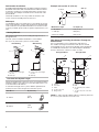
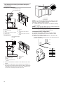
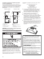
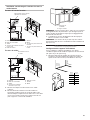
Venting Methods
This range hood is factory set for venting through the roof or
through the wall.
The vent system needed for installation is not included.
A 6" (15.2 cm) round vent system is recommended.
A. 6" (15.2 cm) vent through
the roof
B. Roof cap
A. 6" (15.2 cm) vent through
the wall
B. Wall cap
Calculate Vent System Length
The recommended vent system is 6" (15.2 cm) round vent with a
maximum length of 35 ft (10.7 m). For the best performance, use
no more than three 90° elbows.
To calculate the length of the system, add the equivalent feet
(meters) for each of the vent pieces used in the system.
Vent Piece 6" (15.2 cm)
45° elbow
2.5 ft
(0.8 m)
90° elbow
5.0 ft
(1.5 m)
Example vent system: 6" (15.2 cm)
Maximum Length = 35 ft (10.7 m)
1 - 90° elbow = 5 ft (1.5 m)
1 - wall cap = 0 ft (0 m)
9 ft (2.8 m) straight = 9 ft (2.8 m)
System length = 14 ft (4.3 m)
Non-Vented (recirculating) Installations Through the
Soft/Cabinet
If it is not possible to vent cooking fumes and vapors to
the outside, the range hood can be used in the non-vented
(recirculating) version, using a charcoal lter. Charcoal Filter Kit
is available from the dealer or an authorized parts distributor.
See the “Assistance or Service” section to order.
A. Ceiling
B. Vent cover
C. Soft
D. 6" (15.2 cm) vent
E. Range hood
F. Cabinet
G. Wall
H. 12" (30.5 cm) min. cabinet
height
I. 17" (43.2 cm) min. vent cover
height
NOTE: 12" (30.5 cm) high cabinets without a soft may allow the
6" (15.2 cm) vent and vent cover to be seen.
A
B
Roof Venting Wall Venting
A
B
90˚ elbow
3 ft
(0.93 m)
6 ft (1.8 m)
Wall cap
A
A
B
B
C
D
D
E
E
F
F
G
G
I
H
Through Cabinet Through Soft

7
Electrical Requirements
IMPORTANT: The range hood must be electrically grounded in
accordance with local codes and ordinances, or in the absence
of local codes, with the National Electrical Code, ANSI/NFPA
70 (latest edition) or Canadian Electrical Code, CSA C22.1 No.
0-M91 (latest edition).
If codes permit and a separate ground wire is used, it is
recommended that a qualied electrical installer determine that
the ground path is adequate.
A copy of the above code standards can be obtained from:
National Fire Protection Association
1 Batterymarch Park
Quincy, MA 02169-7471
CSA International
8501 East Pleasant Valley Road
Cleveland, Ohio 44131-5575
■ A 120 volt, 60 Hz, AC only, 15- or 20-amp, fused electrical
circuit is required. A time-delay fuse or circuit breaker is also
recommended. It is recommended that a separate circuit
serving only this range hood be provided.
■ This range hood is equipped with a power supply cord
having a 3 prong grounding plug.
■ To minimize possible shock hazard, the cord must be
plugged into a mating, 3 prong, grounding-type outlet,
grounded in accordance with local codes and ordinances.
If a mating outlet is not available, it is the personal
responsibility and obligation of the customer to have the
properly grounded outlet installed by a qualied electrician.
■ The grounded 3 prong outlet is to be located inside the
cabinet above the range hood at a maximum distance of
33
7
/
16
" (85.0 cm) from where the power cord exits the hood.
The grounded 3 prong outlet must be accessible after
installation of the range hood. See illustration.
Electrical Shock Hazard
Plug into a grounded 3 prong outlet.
Do not remove ground prong.
Do not use an adapter.
Do not use an extension cord.
Failure to follow these instructions can result in death,
fire, or electrical shock.
WARNING
33
7
/16"
(85 cm)
GROUNDING INSTRUCTIONS
SAVE THESE INSTRUCTIONS
■
For a grounded, cord-connected range hood:
This range hood must be grounded. In the event of an
electrical short circuit, grounding reduces the risk of electric
shock by providing an escape wire for the electric current.
This range hood is equipped with a cord having a grounding
wire with a grounding plug. The plug must be plugged into
an outlet that is properly installed and grounded.
WARNING: Improper grounding can result in a risk of
electric shock.
Consult a qualified electrician if the grounding instructions
are not completely understood, or if doubt exists as to
whether the range hood is properly grounded.
Do not use an extension cord. If the power supply cord is too
short, have a qualified electrician install an outlet near the
range hood.

8
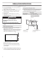
INSTALLATION INSTRUCTIONS
Prepare Location
■ It is recommended that the vent system be installed before
the range hood is installed.
■ Before making cutouts, make sure there is proper clearance
within the ceiling or wall for vent ttings.
■ Making the cutout to the bottom of the cabinet may be
easier to do prior to mounting the cabinet to the wall.
1. Disconnect power.
2. Determine which venting method to use: roof, wall, or
non-vented.
3. Select a at surface for assembling the range hood. Place
covering over that surface.
4. Using two or more people, lift range hood onto covered
surface.
Range Hood Cabinet Cutout
1. Use a saber saw or keyhole saw to cut out the cabinet
bottom inside the cabinet frame.
NOTE: Frameless type cabinets require 3/4" (19 mm) front lip
in the cabinet bottom. A 3/4" (19 mm) thick ller strip (not
supplied) may be required for some types of cabinets (see
Step 3 in the “Install Range Hood” section).
2. Complete cabinet preparation following the instructions for
your type of venting. Determine venting cutout locations and
cut out vent openings in the cabinets, walls, and/or soft.
Venting Outside Through the Roof
1. Measure and mark the lines as the cutout chart shown. Use
a saber saw or keyhole saw to cut an opening through the
top of the cabinet and the roof for the vent.
WARNING
Excessive Weight Hazard
Use two or more people to move and install
range hood.
Failure to do so can result in back or other injury.
A
B
C
D
E
A. Bottom of cabinet cutout
B. Bottom must be cut ush to the inside walls of the cabinet
C. 10
7
⁄
8
" (27.6 cm) min. from the inside of the cabinet front face
D. Min. 3/8 (9.5 mm), max 3/4" (19 mm) thick front face required
for cabinet bottom
E. Front of cabinet
Cutout chart
Cabinet Height Hole Shape and Size
12" (30.5 cm) A 8
17
⁄
64
" wide x 6¼" deep
(21 cm x 15.9 cm) rectangular
opening in the cabinet top is
required for damper transition
clearance.
B*
D
A
E
C
A. Cutout
B. 8
17
⁄
64
" (21 cm)
C. 6¼" (15.9 cm)
D. 6
11
⁄
16
” (17 cm) from cabinet’s
front wall inner side
E. Centerline

9
Cabinet Height Hole Shape and Size
15" (38.1 cm) A 6¼" (15.9 cm) diameter round
opening is required.
A. Cutout
B. Ø 6¼" (15.9 cm)*
C. 7
1
⁄
2
" (19 cm) centerline to
cabinet front
D. Centerline
Cabinet Height Hole Shape and Size
18" (45.7 cm) or
24" (61.0 cm)
A 5¾" (14.6 cm) diameter round
opening is required.
For non-vented (recirculating) installations only, the range hood
can be vented indoors through the top of the cabinet.
For non-vented (recirculating) installations, charcoal lters are
necessary. See the “Range Hood Care” section for instructions
on installing charcoal lters. The Recirculation Kit must be used.
See the “Assistance or Service” section to order.
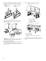
Venting Outside Through the Wall
1. Install transition on top of hood (if removed for shipping) with
two 3.5 x 9.5 mm sheet metal screws.
A. Vent transition
B. 3.5 x 9.5 mm screws
2. Assemble the vent duct that you will use over the
6" (15.2 cm) vent transition. Measure from the bottom
of the range hood liner to the horizontal centerline of the
vent opening (A).
A. Measurement A
B. Horizontal centerline of vent
opening
C. Range hood liner
3. Remove the vent duct from the range hood liner.
Transfer measurement A to the cabinet back wall. Measure
from the underside of the cabinet.
4. Mark the cutout as shown. Use a saber saw or keyhole saw
to cut a round opening through the top of the cabinet and
the exterior wall for the vent.
A. Measurement A
B. Centerline
C. 6¼" (15.9 cm) round
cutout
D
A
B*
C
B
A
A
B
C
A
B
C

10
Non-Vented (recirculating) Installation through the
Cabinet/Soft
Through top of Cabinet:
Recirculating through
the cabinet top wall
Recirculating through
the soft
A. Ceiling
B. Recirculating grid
C. Soft
D. 6" (15.2 cm) round vent system
E. Range hood
F. Cabinet
G. Wall
H. 12" (30.5 cm) min. cabinet
height
I. 17" (43.2 cm) min. vent cover
height
Through Soft:
A. Ceiling
B. Recirculating grid
C. Soft
D. 6" (15.2 cm) round vent
system
E. Range hood
F. Cabinet
G. Wall
1. Measure and mark the centerline of the cabinet to the soft
above.
2. Measure from the bottom of the cabinet to the centerline of
the where the vent will come through the soft or cabinet top
wall. Mark the location and use a saber saw or keyhole saw
to cut a 5¾" (14.6 cm) hole for the vent cover.
A. Vent cover
B. Centerline
NOTE: For 12" (30.5 cm) high cabinets a 6¼" deep x 8" wide
(14.6 cm x 20.3 cm) rectangular opening in the cabinet top is
required for damper transition clearance.
3. Consider the cutout chart measures to make the openings
on the cabinet.
NOTE: 12" (30.5 cm) high cabinets without a soft may allow the
6" (15.2 cm) vent and vent cover to be seen.
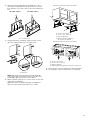
Complete Preparation
Installation brackets conguration
To assemble the installation brackets, you must consider
the cabinet's material thickness and your cabinet's width
(30" [76.2 cm] or 36" [91.44 cm]).
1. Measure your cabinet material thickness, then locate the
bracket’s installation holes, based on your cabinet thickness
(see the chart below).
A
G
D
F
E
I
H
A
G
F
E
B
D
A
B
Cabinet
material
thickness
12
3
5
4
Bracket
marks
Cabinet
Thickness
1 3/8”
2 1/2”
3 5/8”
4 3/4”
5 1”

11
2. Orient the brackets depending on the width (30" or 36") of
your cabinet as depicted in the images below, then secure
them with three 4 x 15 mm screws on the selected thickness
hole.
3. Using the bracket as a template, mark four spots in each
side of the cabinet to drill 1/8" (3 mm) pilot holes.
NOTE: Align the bracket with the front and the back side
of the cabinet and ensure that the bottom of the bracket is
installed tight against the bottom of the cabinet.
4. Attach a bracket using four 4.5 x 13 mm screws to each side
of the cabinet, and tighten.
Additional washers in hardware package are supplied as
spacers for cabinet walls thinner than 1/2" (13 mm).
30" width cabinet 36" width cabinet
A A
A
A. Pilot holes
Bracket Orientation for 36" (91.4 cm) Cabinet
A. 36" (91.4 cm) cabinet
B. Screws - 4.5 x 13 mm (8)
C. Washers (optional)
D. Mounting bracket (4) (position for 36" [91.4 cm] cabinet)
5. Install the vent system according to the method needed.
6. Use caulking to seal the exterior wall or roof opening.
Bracket Orientation for 30" (76.2 cm) Cabinet
A. 30" (76.2 cm) cabinet
B. Screws - 4.5 x 13 mm (8)
C. Washers (optional)
D. Mounting bracket (4) (position
for 30" [76.2 cm] cabinet)
A
B
C
D
A
B
C
D
A. 4 x 15 mm screws

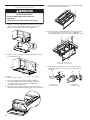
12
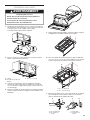
Install Range Hood
1. Using two or more people, lift the hood liner into the cabinet
until it snaps into the 4 hooks located on the mounting
brackets. The hood liner will remain suspended.
2. Attach the 4.2 x 8 mm (8) screws into the slotted openings.
Do not tighten screws.
3. Center the canopy in the cabinet. Align the bottom of
the canopy with the bottom of the cabinet. Install the
4.2 x 8 mm T20
®
screws into the mounting bracket
and tighten all mounting screws.
4. Place the lower canopy assembly in the front side of the
cabinet and slide it through the bracket as shown in drawing.
5. Open perimetric panel and remove the metal grease lters
from the lower canopy assembly.
6. Secure the lower canopy assembly to the hood usingthe
4x15 mm and the 4.5 x 13 mm screws as depicted
inthediagram below to fasten the panel. Tighten to secure.
7. Plug lamps and control wire connectors from the lower
canopy assembly into the connectors located inside the
hood liner.
WARNING
Excessive Weight Hazard
Use two or more people to move and install
range hood.
Failure to do so can result in back or other injury.
A
C
B
A. Cabinet
B. Hood liner canopy assembly
C. Screws - 4.2 x 8 mm (8)
A. Screws - 4 x 15 mm (4)
B. Screws - 4.5 x 13 mm (3)
A
B
A. Control wire
B. Motor box wire
A. Lamp wire
B. Motor box wire
A AB B

13
Connect the Vent System
Vented Installations
1. Connect the vent system to the range hood vent opening.
Seal the connection with clamps.
Non-Vented (recirculating) Installations
1. Connect the vent system to the range hood vent opening.
Seal the connection with clamps.
2. Install vent cover that is included with the recirculation
accessory kit.
3. Install charcoal lters. See the “Range Hood Care” section.
To order replacement kits, see the “Assistance or Service”
section.
Complete Installation
1. Replace grease lters. See the “Range Hood Care” section.
2. Plug 3 prong power cord into a grounded 3 prong outlet
located inside the cabinet above the range hood.
3. Check the operation of the range hood fan and light. See the
“Range Hood Use” section.
If range hood does not operate, check to see whether a
circuit breaker has tripped or a household fuse has blown.
NOTE: To get the most efcient use from your new range
hood, read the “Range Hood Use” section.
4. Reinstall cabinet doors if removed. Use the assembly
instructions that came with the cabinet.
Electrical Shock Hazard
Plug into a grounded 3 prong outlet.
Do not remove ground prong.
Do not use an adapter.
Do not use an extension cord.
Failure to follow these instructions can result in death,
fire, or electrical shock.
WARNING

14
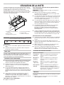
RANGE HOOD USE
The range hood is designed to remove smoke, cooking vapors,
and odors from the cooktop area. For best results, start the hood
before cooking and allow it to operate several minutes after the
cooking is complete to clear all smoke and odors from the
kitchen. The hood controls are located on the front of the range
hood.
Range Hood Controls
NOTES:
■ To activate the controls, press and release the desired
button.
■ The control feature button will be lit when a control feature is
turned on.
Sleep Mode
The range hood automatically enters Sleep Mode when not in
use. After 10 minutes of no range hood activity, all of the control
button lights will turn off. To deactivate Sleep Mode, press any
button.
Auto Sense
■ Auto Sense allows the range hood fan to turn on
automatically when it senses heat higher than its allowable
temperature limit.
■ When Auto Sense is on, the fan speed will increase
or decrease based on the temperature Auto Sense is
measuring.
■ Auto Sense can be manually increased by pressing a higher
fan speed. The fan will run at the selected speed for 10
minutes before returning to the speed selected for Auto
Sense.
■ If Auto Sense is on, the Auto Fan button light will turn off and
go into Sleep Mode when the vent hood is not in use. If the
vent hood is turned on by the consumer or by Auto Sense,
the Auto fan button light will turn on.
To set Auto Sense:
■ Press AUTO Fan.
To Select Auto Sense Cooktop Type:
NOTE: The range hood is factory-set for the gas cooktop mode.
■ Press and hold AUTO Fan for 5 seconds to switch between
the gas cooktop and electric cooktop modes.
■ The Auto Fan button light will ash 5 times when the range
hood is changed to the electric cooktop mode. Auto Sense
is now set to work with electric cooktops and ranges.
■ The Auto Fan button light will ash three times when the
range hood is changed to the gas cooktop mode. Auto
Sense is now set to work with gas cooktops and ranges.
■ Changing the cooktop type will change the temperature limit
for Auto Sense to turn on. When the range hood senses a
high enough temperature, the fan will start automatically.
■ When the temperature drops below the set temperature limit,
the fan will stop automatically. The Auto Fan button light will
turn off after the range hood enters Sleep Mode, but Auto
Sense is still active.
To Deactivate Auto Sense:
■ If the Auto Fan button is lit, press AUTO Fan once to
deactivate Auto Sense. The Auto button light will turn off.
■ If Auto Sense is in Sleep Mode, press AUTO Fan once to
deactivate Sleep Mode and turn on the Auto Fan button
light.
■ Press AUTO Fan again to deactivate Auto Sense and turn off
the Auto Fan button light.
■ Auto Sense will turn off automatically after two hours of no
activation of the Auto Sense system. To reset Auto Sense,
press AUTO Fan.
Manual Vent Functions
Timer
The range hood can be set to automatically turn off after
15 minutes.
1. Press and hold the desired fan speed button for 2 seconds.
The fan will run on the chosen speed for 15 minutes and the
fan speed button light will ash continuously.
After 15 minutes, the fan will turn off automatically.
2. Press the desired fan speed button again while the fan timer
is running to cancel the fan timer.
NOTE: Changing the fan speed or turning Auto Sense on will
also cancel the 15-minute timer.
Light
The range hood has both task and ambient lighting.
To operate the lights:
1. Touch LIGHT once to turn the LED task lights to high setting.
2. Touch LIGHT again to turn LED task lights to low setting.
3. Touch LIGHT a third time to turn the LED lights off.
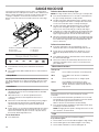
E
A E
C
B
F
D
A. Blower and LED lamp controls
B. Grease lter
C. Grease lter handle
D. Perimetric cover
E. LED lights
F. Hood liner
Fan Speeds
Low Press LOW to turn the fan on at LOW speed.
Med Press MED to turn the fan on at Medium
speed.
Hi Press HI to turn the fan on at High speed.
Boost Press BOOST to turn the fan on at the
highest speed. Boost will automatically turn
off after 10 minutes and the fan will switch to
High speed.

15
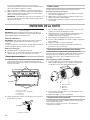
RANGE HOOD CARE
Cleaning
IMPORTANT: Clean the hood and grease lters frequently
according to the following instructions. Replace grease lter
before operating hood.
Exterior Surfaces:
IMPORTANT: To avoid damage to the exterior surface, do not
use steel wool or soap-lled scouring pads.
Always wipe dry to avoid water marks.
Cleaning Method:
■ Liquid detergent soap and water, or all-purpose cleanser
■ Wipe with damp soft cloth or nonabrasive sponge, then rinse
with clean water and wipe dry.
Metal Grease Filter
1. Open the panel. Grasp panel at the front corners and pull
down to disengage the two catch pins from the spring
catches. The panel is attached at the rear and will rotate
down.
2. Remove each lter by pulling the spring-release handle and
then pulling down the lter.
3. Wash metal lter as needed in dishwasher or hot detergent
solution.
4. Reinstall the lter by making sure the spring-release handles
are toward the front. Insert metal grease lter into upper
track.
5. Pull the spring release handle down.
6. Push up on metal lter and release handle to latch into place.
7. Repeat steps 1-5 for the other lter.
8. Close the panel. Engage the two pins in the spring catches
to secure.
Non-Vented (recirculating) Installation Filters:
The charcoal lter is not washable. It should last up to 6 months
with normal use. Replace with Charcoal Filter Kit. See the
“Accessories” section for information on ordering.
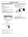
To replace charcoal lter:
1. Cover the grille that covers the blower motor with the
charcoal lter so that the slots on the lter correspond to the
pins on the sides of the motor grille.
2. Turn the charcoal lter clockwise to lock it.
3. Repeat steps 1-2 on the other lter.
Replacing an LED Lamp
The LED lights are replaceable by a service technician only.
See the “Assistance and Service” section for service contact
information.
D
C
B
A
A. Metal lters
B. Stainless steel panel
C. Catch pins (2)
D. Spring catches (2)
A
A. Spring-release handle
A
B
C
A. Charcoal lter
B. Pins
C. Blower motor

16
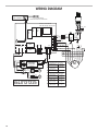
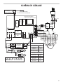
WIRING DIAGRAM
SEL0131225
BK - N
WH - BL
RD - R
BK - N
WH - BL
BU - BU
GR - GRIS
BU - BU
M
3
2
1
4
5
6
7
8
9
BU - BU
YL/GN - JA/VE
BR - MAR
YL - JA
WH - BL
RD - R
GR - GRIS
BK - N
AUTO-SPEED SENSOR
CAPTEUR DE VITESSE AUTOMATIQUE
User Interface
Interface Utilisateur
RD - R
BK - N
RD - R
RD - R
BK - N
LED
DEL
BK - N
RD - R
BK - N
BR - MAR
YL - JA
YL/GN - JA/VE
MOTOR SPECIFICATIONS
CARACTERISTIQUES DU MOTEUR
POWER SUPPLY
ALIMENTATION
FREQUENCY
FRÉQUENCE
POWER ABSORTION
PUISSANCE NOMINALE
120 VAC
120 VCA
60 HZ
240 W
MOTOR RESISTANCE (Ohms)
RÉSISTANCE DU MOTEUR (Ohms)
BLUE - BLACK
BLEU - NOIR
BLUE - GREY
BLEU - GRIS
BLUE - RED
BLEU - ROUGE
BLUE - WHITE
BLEU - BLANC
17.7
17,7
27.1
27,1
34.6
34,6
41.2
41,2
YL/GN - JA/VE
EMI
FILTER
FILTRE
EMI
WH - BL
BK - N
WH - BL
BK - N
YL - JA
BU - BU
L
N
C
2
3
1
4
La2
N
GND
PWM
RL1
RL2
RL5
N
La1
Electronic Power Board
Carte Électronique de Puissance
RL4
RL3
BK - N
WH - BL
YL/GN - JA/VE
RD - R
BK - N
2
1
DIMMABLE
LED DRIVER
ATTÉNUABLE
PILOT DEL
2
1
12.5uF
LED
DEL

17
ASSISTANCE OR SERVICE
If you need service
Please refer to the warranty page in these instructions.
If you need replacement parts
If you need to order replacement parts, we recommend that
you use only factory specied parts. Factory specied parts
willt right and work right because they are made with the
sameprecision used to build every new appliance.
To locate factory specied replacement parts in your area,
callthe following customer assistance telephone number
oryournearest designated service center.
In the U.S.A.
Call the Whirlpool Customer eXperience Center toll-free:
1-800-253-1301 or visit our website at www.whirlpool.com.
Our consultants provide assistance with:
■ Scheduling of service. Whirlpool designated service
technicians are trained to fulll the product warranty
andprovide after-warranty service anywhere in the
UnitedStates.
■ Features and specications on our full line of appliances.
■ Referrals to local dealers.
■ Installation information.
■ Use and maintenance procedures.
■ Accessory and repair parts sales.
■ Specialized customer assistance (Spanish speaking,
hearingimpaired, limited vision, etc.).
For further assistance
If you need further assistance, you can write to Whirlpool
Corporation with any questions or concerns at:
Whirlpool Brand Home Appliances
Customer eXperience Center
553 Benson Road
Benton Harbor, MI 49022-2692
Please include a daytime phone number in your correspondence.
In Canada
Call the Whirlpool Canada LP Customer eXperience
Center toll free: 1-800-807-6777 or visit our website
www.whirlpool.ca.
Our consultants provide assistance with:
■ Scheduling of service. Whirlpool designated service
technicians are trained to fulll the product warranty
andprovide after-warranty service anywhere in Canada.
■ Features and specications on our full line of appliances.
■ Referrals to local Whirlpool dealers.
■ Use and maintenance procedures.
■ Accessory and repair parts sales.
■ Referrals to local dealers, repair parts distributors,
andservice companies.
For further assistance
If you need further assistance, you can write to Whirlpool
Canada LP with any questions or concerns at:
Whirlpool Brand Home Appliances
Customer eXperience Centre
Whirlpool Canada LP
200 - 6750 Century Ave.
Mississauga, Ontario L5N 0B7
Please include a daytime phone number in your correspondence.
Accessories
Recirculation Kit
(for non-vented installations only)
Order Part Number W10490330
Replacement Charcoal Filters
(for non-vented installations only)
Order Part Number W10272068

18
11/14
IF YOU NEED SERVICE:
1. Before contacting us to arrange service, please determine whether your product requires repair. Some
questions can be addressed without service. Please take a few minutes to review the Troubleshooting or
Problem Solver section of the Use and Care Guide, scan the QR code on theright to access additional
resources, or visit www.whirlpool.com/product_help.
2. All warranty service is provided exclusively by our authorized Whirlpool Service Providers. IntheU.S.and
Canada, direct all requests for warranty service to:
Whirlpool Customer eXperience Center
In the U.S.A., call 1-800-253-1301. In Canada, call 1-800-807-6777.
If outside the 50 United States or Canada, contact your authorized Whirlpool dealer to determine whether
another warranty applies.
WHIRLPOOL
®
MAJORAPPLIANCE
LIMITEDWARRANTY
ATTACH YOUR RECEIPT HERE. PROOF OF PURCHASE IS REQUIRED
TO OBTAIN WARRANTY SERVICE.
Please have the following information available when you call the
Customer eXperience Center:
■ Name, address and telephone number
■ Model number and serial number
■ A clear, detailed description of the problem
■ Proof of purchase including dealer or retailer name and address
ONE YEAR LIMITED WARRANTY
WHAT IS COVERED WHAT IS NOT COVERED
For one year from the date of purchase,
when this major appliance is installed,
operated and maintained according to
instructions attached to or furnished
with the product, Whirlpool Corporation
or Whirlpool Canada LP (hereafter
“Whirlpool”) will pay for Factory
Specied Replacement Parts and repair
labor to correct defects in materials or
workmanship that existed when this
major appliance was purchased, or at
its sole discretion replace the product.
In the event of product replacement,
your appliance will be warranted for
the remaining term of the original unit’s
warranty period.
YOUR SOLE AND EXCLUSIVE
REMEDY UNDER THIS LIMITED
WARRANTY SHALL BE PRODUCT
REPAIR AS PROVIDED HEREIN.
Service must be provided by a
Whirlpool designated service company.
This limited warranty is valid only in
the United States or Canada and
applies only when the major appliance
is used in the country in which it was
purchased. This limited warranty is
effective from the date of original
consumer purchase. Proof of original
purchase date is required to obtain
service under this limited warranty.
1. Commercial, non-residential, multiple-family use, or use inconsistent with published user, operator or
installation instructions.
2. In-home instruction on how to use your product.
3. Service to correct improper product maintenance or installation, installation not in accordance with
electrical or plumbing codes or correction of household electrical or plumbing (i.e. house wiring, fuses
or water inlet hoses).
4. Consumable parts (i.e. light bulbs, batteries, air or water lters, preservation solutions, etc.).
5. Defects or damage caused by the use of non-genuine Whirlpool parts or accessories.
6. Conversion of products from natural gas or L.P. gas.
7. Damage from accident, misuse, abuse, re, oods, acts of God or use with products not approved by
Whirlpool.
8. Repairs to parts or systems to correct product damage or defects caused by unauthorized service,
alteration or modication of the appliance.
9. Cosmetic damage including scratches, dents, chips, and other damage to the appliance nishes
unless such damage results from defects in materials and workmanship and is reported to Whirlpool
within 30 days.
10. Discoloration, rust or oxidation of surfaces resulting from caustic or corrosive environments including
but not limited to high salt concentrations, high moisture or humidity or exposure to chemicals.
11. Food or medicine loss due to product failure.
12. Pick-up or delivery. This product is intended for in-home repair.
13. Travel or transportation expenses for service in remote locations where an authorized Whirlpool
servicer is not available.
14. Removal or reinstallation of inaccessible appliances or built-in xtures (i.e. trim, decorative panels,
ooring, cabinetry, islands, countertops, drywall, etc.) that interfere with servicing, removal or
replacement of the product.
15. Service or parts for appliances with original model/serial numbers removed, altered or not easily
determined.
The cost of repair or replacement under these excluded circumstances shall be borne by
thecustomer.
DISCLAIMER OF IMPLIED WARRANTIES
IMPLIED WARRANTIES, INCLUDING ANY IMPLIED WARRANTY OF MERCHANTABILITY OR IMPLIED WARRANTY OF FITNESS FOR A
PARTICULAR PURPOSE, ARE LIMITED TO ONE YEAR OR THE SHORTEST PERIOD ALLOWED BY LAW. Some states and provinces do not allow
limitations on the duration of implied warranties of merchantability or tness, so this limitation may not apply to you. This warranty gives you specic
legal rights, and you also may have other rights that vary from state to state or province to province.
DISCLAIMER OF REPRESENTATIONS OUTSIDE OF WARRANTY
Whirlpool makes no representations about the quality, durability, or need for service or repair of this major appliance other than the representations
contained in this warranty. If you want a longer or more comprehensive warranty than the limited warranty that comes with this major appliance, you
should ask Whirlpool or your retailer about buying an extended warranty.
LIMITATION OF REMEDIES; EXCLUSION OF INCIDENTAL AND CONSEQUENTIAL DAMAGES
YOUR SOLE AND EXCLUSIVE REMEDY UNDER THIS LIMITED WARRANTY SHALL BE PRODUCT REPAIR AS PROVIDED HEREIN. WHIRLPOOL
SHALL NOT BE LIABLE FOR INCIDENTAL OR CONSEQUENTIAL DAMAGES. Some states and provinces do not allow the exclusion or limitation of
incidental or consequential damages, so these limitations and exclusions may not apply to you. This warranty gives you specic legal rights, and you
also may have other rights that vary from state to state or province to province.
www.whirlpool.com/product_help

19
SÉCURITÉ DE LA HOTTE DE CUISINIÈRE

20
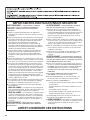
IMPORTANTES INSTRUCTIONS DE SÉCURITÉ
LIRE ET CONSERVER CES INSTRUCTIONS
AVERTISSEMENT : POUR RÉDUIRE LE RISQUE
D'INCENDIE, CHOC ÉLECTRIQUE OU DOMMAGES
CORPORELS, RESPECTER LES INSTRUCTIONS
SUIVANTES :
■ Utiliser cet appareil uniquement dans les applications
envisagées par le fabricant. Pour toute question, contacter
le fabricant.
■
Avant d'entreprendre un travail d'entretien ou de nettoyage,
interrompre l'alimentation de la hotte au niveau du tableau
de disjoncteurs, et verrouiller le tableau de disjoncteurs
pour empêcher tout rétablissement accidentel de
l'alimentation du circuit. Lorsqu'il n'est pas possible de
verrouiller le tableau de disjoncteurs, placer sur le tableau
de disjoncteurs une étiquette d'avertissement proéminente
interdisant le rétablissement de l'alimentation.
■ Tout travail d'installation ou câblage électrique doit être
réalisé par une personne qualifiée, dans le respect des
prescriptions de tous les codes et normes applicables, y
compris les codes du bâtiment et de protection contre les
incendies.
■ Ne pas faire fonctionner un ventilateur dont le cordon ou la
fiche est endommagé(e). Jeter le ventilateur ou le retourner
à un centre de service agréé pour examen et/ou réparation.
■ Une source d'air de débit suffisant est nécessaire pour le
fonctionnement correct de tout appareil à gaz (combustion
et évacuation des gaz à combustion par la cheminée), pour
qu'il n'y ait pas de reflux des gaz de combustion. Respecter
les directives du fabricant de l'équipement de chauffage et
les prescriptions des normes de sécurité - comme celles
publiées par la National Fire Protection Association (NFPA)
et l'American Society for Heating, Refrigeration and Air
Conditioning Engineers (ASHRAE), et les prescriptions des
autorités réglementaires locales.
■ Lors d'opérations de découpage et de perçage dans un mur
ou un plafond, veiller à ne pas endommager les câblages
électriques ou canalisations qui peuvent s'y trouver.
■ Les ventilateurs d'évacuation doivent toujours décharger
l'air à l'extérieur.
MISE EN GARDE : Cet appareil est conçu uniquement
pour la ventilation générale. Ne pas l'utiliser pour l'extraction
de matières ou vapeurs dangereuses ou explosives.
MISE EN GARDE : Pour minimiser le risque d'incendie
et évacuer adéquatement les gaz, veiller à acheminer l'air
aspiré par un conduit jusqu'à l'extérieur - ne pas décharger
l'air aspiré dans un espace vide du bâtiment comme une
cavité murale, un plafond, un grenier, un vide sanitaire ou
un garage.
AVERTISSEMENT : POUR RÉDUIRE LE RISQUE
D'INCENDIE, UTILISER UNIQUEMENT DES CONDUITS
MÉTALLIQUES.
AVERTISSEMENT : POUR MINIMISER LE RISQUE
D'UN FEU DE GRAISSE SUR LA CUISINIÈRE :
■ Ne jamais laisser un élément de surface fonctionner à
puissance de chauffage maximale sans surveillance. Un
renversement/débordement de matière graisseuse pourrait
provoquer une inflammation et la génération de fumée.
Utiliser une puissance de chauffage moyenne ou basse
pour le chauffage d'huile.
■
Veiller à toujours faire fonctionner le ventilateur de la hotte
lors de la cuisson avec une puissance de chauffage élevée
ou lors de la cuisson d'un mets à flamber (à savoir crêpes
Suzette, cerise jubilée, steak au poivre flambé).
■ Nettoyer fréquemment les ventilateurs d'extraction. Veiller à
ne pas laisser la graisse s'accumuler sur les surfaces du
ventilateur ou des filtres.
■ Utiliser toujours un ustensile de taille appropriée. Utiliser
toujours un ustensile adapté à la taille de l'élément
chauffant.
AVERTISSEMENT : POUR RÉDUIRE LE RISQUE DE
DOMMAGES CORPORELS APRÈS LE DÉCLENCHEMENT
D'UN FEU DE GRAISSE SUR LA CUISINIÈRE, APPLIQUER
LES RECOMMANDATIONS SUIVANTES :
a
■ Placer sur le récipient un couvercle bien ajusté, une tôle à
biscuits ou un plateau métallique POUR ÉTOUFFER LES
FLAMMES, puis éteindre le brûleur. VEILLER À ÉVITER
LES BRÛLURES. Si les flammes ne s'éteignent pas
immédiatement, ÉVACUER LA PIÈCE ET APPELER LES
POMPIERS.
■ NE JAMAIS PRENDRE EN MAIN UN RÉCIPIENT
ENFLAMMÉ - vous risquez de vous brûler.
■ NE PAS UTILISER D'EAU, ni un torchon humide - ceci
pourrait provoquer une explosion de vapeur brûlante.
■
Utiliser un extincteur SEULEMENT si :
– Il s'agit d'un extincteur de classe ABC, dont on connaît le
fonctionnement.
– Il s'agit d'un petit feu encore limité à l'endroit où il s'est
déclaré.
– Les pompiers ont été contactés.
– Il est possible de garder le dos orienté vers une sortie
pendant l'opération de lutte contre le feu.
a
Recommandations tirées des conseils de sécurité en cas
d'incendie de cuisine publiés par la NFPA.
■ AVERTISSEMENT : Pour réduire le risque d'incendie
ou de choc électrique, ne pas utiliser ce ventilateur avec un
quelconque dispositif de réglage de la vitesse à semi-
conducteurs.
La page est en cours de chargement...
La page est en cours de chargement...
La page est en cours de chargement...
La page est en cours de chargement...
La page est en cours de chargement...
La page est en cours de chargement...
La page est en cours de chargement...
La page est en cours de chargement...
La page est en cours de chargement...
La page est en cours de chargement...
La page est en cours de chargement...
La page est en cours de chargement...
La page est en cours de chargement...
La page est en cours de chargement...
La page est en cours de chargement...
La page est en cours de chargement...
-
 1
1
-
 2
2
-
 3
3
-
 4
4
-
 5
5
-
 6
6
-
 7
7
-
 8
8
-
 9
9
-
 10
10
-
 11
11
-
 12
12
-
 13
13
-
 14
14
-
 15
15
-
 16
16
-
 17
17
-
 18
18
-
 19
19
-
 20
20
-
 21
21
-
 22
22
-
 23
23
-
 24
24
-
 25
25
-
 26
26
-
 27
27
-
 28
28
-
 29
29
-
 30
30
-
 31
31
-
 32
32
-
 33
33
-
 34
34
-
 35
35
-
 36
36


KitchenAid KVUB400GSS00 Le manuel du propriétaire
- Catégorie
- Hottes
- Taper
- Le manuel du propriétaire
- Ce manuel convient également à
