
1
Betriebsanleitung
S/W und Farb-Video Quad Splitter
Modellreihe: VCQ-6057, VBQ-6045
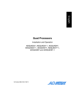
Operating Instructions
B/W and Colour Video Quad Splitter
Model Series: VCQ-6057, VBQ-6045
Mode d’emploi
Quadravision noir/blanc et couleur
Série: VCQ-6057, VBQ-6045
Instrucciones de manejo
Quad Splitter Video en B/N en color
Series de modelos: VCQ-6057, VBQ-6045

2
3
Inhaltsverzeichnis
1 Sicherheitshinweise/Pege ...............................................................2
2 Mitgeliefertes Zubehör.......................................................................3
3 Technische Merkmale ........................................................................3
4 Lage und Funktion der Bedienelemente............................................3
A Frontseite......................................................................................3
B Rückseite .....................................................................................4
5 Installation..........................................................................................6
5.1 Grundsätzliches Verkabelungsschema
mit Alarm Ein-/Ausgang ................................................................6
5.2 VCR-Wiedergabe...........................................................................7
5.3 Videorekorder-Anschluss für Aufzeichnung und
Start/Stop-Betrieb.........................................................................7
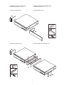
5.4 Montage des 19”-Einschub-Winkelsets.........................................8
5.5 Fernsteuerungs-Anschluss............................................................9
6 Bedienung...........................................................................................9
6.1 Bildschirm-Menü .........................................................................9
6.2 Quad-Darstellungs-Modus .........................................................12
6.3 Vollbild-Darstellung ....................................................................12
6.4 Standbild-Darstellung der Kamerabilder (FREEZE) ......................12
6.5 Alarm Einstellungen ...................................................................13
6.6 Sequenzieller Umlauf ..................................................................13
6.7 VCR-Betrieb ...............................................................................14
7 Fernbedienbetrieb ............................................................................14
7.1 Belegung der 9-pol. D-Sub-Buchse ............................................14
7.2 ASCII Steuercodes.......................................................................15
8 Zubehör.............................................................................................16
9 Technische Daten ............................................................................17
Anhang ....................................................................................................35
1 Sicherheitshinweise / Pege
• Bevor Sie das Gerät anschließen und in Betrieb nehmen, lesen Sie bitte
zuerst die Sicherheitshinweise und die Betriebsanleitung.
• Bewahren Sie die Betriebsanleitung für spätere Verwendung sorgfältig auf.
• Die Lüftungsschlitze des Gerätes niemals abdecken.
• Das Gerät gegen Eindringen von Wasser und Feuchtigkeit schützen.
Sollte dennoch Feuchtigkeit eingedrungen sein, das Gerät nie unter
diesen Bedingungen einschalten und zur Überprüfung an eine qualizierte
Servicestelle geben.
• Den Deckel des Gerätes nicht öffnen.
Instandsetzung nur durch qualiziertes Servicepersonal.
• Das Gerät nur in einem Temperaturbereich von 0 bis +50°C und einer
Luftfeuchtigkeit bis max. 90% betreiben.
• Niemals metallische oder andere Gegenstände durch die Lüftungsschlitze
stecken, dies könnte das Gerät dauerhaft schädigen.
• Das Gerät ist vor großer Hitze, Staub, Feuchtigkeit und Vibrationsein-
wirkung zu schützen.
• Die Belastung des Gehäuses durch schwere Gegenstände ist zu
vermeiden.
• Zur Reinigung des Gerätegehäuses nur ein mildes Haushaltsmittel
verwenden. Niemals Verdünner oder Benzin benutzen. Dies kann die
Oberäche dauerhaft schädigen.
Contents
1 Safety Instructions / Cleaning ..........................................................2
2 Supplied Accessories ........................................................................3
3 Features .............................................................................................3
4 Operating Control and their Functions .............................................3
A Front Panel ..................................................................................3
B Rear Panel ...................................................................................4
5 Installation Notes ...............................................................................6
5.1 Basic System Connection with Alarm
Inputs and Outputs .......................................................................6
5.2 VCR Connection for Zoom on Playback Operation..........................7
5.3 VCR Connection for Tape Record Start and Stop Control ...............7
5.4 Use of Rack Mount Kit ..................................................................8
5.5 Remote Control Connection ..........................................................9
6 Operating ............................................................................................9
6.1 The Setup Menu ...........................................................................9
6.2 The Quad Display Mode .............................................................12
6.3 The Full Screen Display Mode ....................................................12
6.4 The Still Frame Display Mode (FREEZE) ......................................12
6.5 Alarm Operations .......................................................................13
6.6 The Auto-Sequence Mode ..........................................................13
6.7 VCR Operations ..........................................................................14
7 Remote Control Operations..............................................................14
7.1 Pin Assignment of the 9 pin D-Sub Connector ............................14
7.2 ASCII Command Codes ...............................................................15
8 Accessories .....................................................................................16
9 Technical Data .................................................................................18
Annex ... ...................................................................................................35
1 Safety Instructions / Cleaning
• The following instructions are for your own safety and should be
observed without fail.
• Please read these safety and operating instructions before putting the
system into operation.
• Keep the operating instructions in a safe place for later use.
• Do not block the ventilation slots.
• To prevent re or shock hazard, do not expose this appliance to rain,
water, wet locations. Should any liquid or solid object fall into the cabinet,
unplug the unit and have it checked by the qualied personnel before
operating it any further.
• Do not remove the screws of the cover. Refer servicing to qualied
service personnel.
• Use the quad unit under conditions where temperature is within 0°C to
50°C and humidity is below 90%.
• Do not drop foreign materials such as water, liquid or metallic parts
through slots. This action could permanently damage the quad unit.
• Keep away from heating elements and do not expose to wet, dust and
vibration conditions.
• Do not place heavy items on the quad unit.
• Do not use strong or abrasive detergents when cleaning the units body.
Use a dry cloth to clean the cabinet when dirty. In case the dirt is hard
to remove, use a mild detergent and wipe gently.

2
3
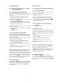
VCQ-6057 Farbe (Colour)
VBQ-6045 S/W (B/W)
2 Mitgeliefertes Zubehör
• Netzadapter 230VAC / 12VDC
• Betriebsanleitung
3 Technische Merkmale
• Hochauösende Quadbild-Kombination von vier S/W- oder Farbkamera-
signalen zur Wiedergabe und Aufzeichnung im Real-Time Modus.
• Manuelle oder sequenzielle Vollbild-Darstellung aller Kamerasignale, oder
des Quadbildes, auf dem Monitorschirm.
• Uhrzeit-/Datums- und Kameratitel-Anzeige für jeden Kanal sowie
Bildschirm-Programmierung
• Einfache Tasten-Bedienung
• Alarm-Auslösung durch externe Kontakte, bzw. bei der Unterbrechung
eines Kamerasignal-Einganges
• Vollbilddarstellung der alarmierten Kamera und Einschaltung eines ex-
ternen Aufzeichnungs-Gerätes, (z.B. VCR). Einstellbare Alarm-Haltedauer
• Eingebauter akustischer Alarmgeber (abschaltbar)
• Der Ausfall einer Videosignalquelle, durch einen Kameradefekt oder eine
Kabelunterbrechung, bewirkt das „Einfrieren” des letzten an diesem
Eingang angekommenen Bildes.
• Keine synchronisierten Kameras erforderlich
• Fernsteuerung mittels Fernbedienung oder PC, über eine RS-232-Schnitt-
stelle
4 Lage und Funktion der Bedienelemente
A Frontseite
2 Supplied Accessories
• 230VAC / 12VDC Adapter
• Operating instruction manual
3 Features
• Four B/W or colour camera outputs can be combined into one video signal
for simultaneous display and recording.
• User selected video display mode including quad display mode
(cameras 1-4) and full screen sequential switching.
• On-screen time/date, title display for each channel, and on-screen
set-up menu
• Simple push-button operation
• Alarm detection for sensor contact closure and video loss in camera
inputs
• Alarm called full screen display with VCR start/stop and external alarm
duration control
• Built-in buzzer for alarm detection acknowledgement
• Freeze of last picture before video loss
• Does not require special cameras or synchronization.
• Remote control/RS-232 control through keypad or PC
4 Operating Control and their Functions
A Front Panel
2 Verriegelung (Lock)
Durch Drücken der Taste Lock, für die Dauer von mind. 2 sek., wird die
frontseitige Bedienung gesperrt. Eine erneute Betätigung der Taste für 2 sek.
hebt die Sperrung wieder auf.
3 VCR-Wiedergabe/Zoom-Funktion (VCR)
Zur VCR-Wiedergabe ist diese Taste zu betätigen. Bei gedrückter Taste sind
„Sequenz, Quadbild und Kanalauswahl” unwirksam.
2 Lock
Security lock-out button. Push this button for 2 seconds to enable control
panel lock-out function. Push this button again for 2 seconds to disable the
function.
3 VCR
Press this button for VCR-play back. In this mode, the output video is
displaying the video signal from VCR.

4
5
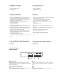
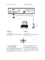
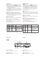
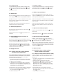
B Rear Panel
2 and 3 Menu
Push these two buttons simultaneously to get into menu setup mode and
display page 1 of system setup menu. Push these two buttons simulta-
neously again to display page 2 of the setup menu. Use page 1 to program
time/date, dwell time and camera title and page 2 to congure alarm
operations. Under menu setup mode, channel select buttons 6 are used for
cursor control and text selection to program the setup menu. Push the setup
buttons simultaneously again to save the setting.
Push the setup buttons to save the setting and push the buttons to get back
to ordinary operation mode.
4 Sequence
Push this button to enable full page auto sequencing mode. Push this button
again to disable it.
5 Quad Display
Push this button to switch between quad/full screen display mode.
6 Channel Select Buttons, FREEZE
When operated in full screen display mode, these buttons are used to select
specic camera to be displayed in full screen.
When operated in quad mode, these buttons are used to freeze any specic
camera by pushing the corresponding button.
2 und 3 Bildschirm-Menü
Durch gleichzeitiges Betätigen der Tasten 2 und 3 gelangt man zur Seite
1 des Bildschirm-Menüs. Eine weitere, gleichzeitige Betätigung der beiden
Tasten lässt die Seite 2 erscheinen.
Auf Seite 1 werden die Funktionen: Uhrzeit/Datum, Verweildauer und Kame-
ratitel eingegeben, Seite 2 dient zur Konguration der Alarmverarbeitung.
Über die Tasten 6 wird der Cursor bewegt (s. Symbole über den Tasten) und
die einzugebenden Textzeichen ausgewählt. Eine weitere Betätigung beider
Tasten speichert die programmierten Daten, nach einer erneuten Betätigung
gelangt man in die normale Betriebsart zurück.
4 Sequenzschaltung, Vollbild-/Halbbildschaltung
Durch Betätigung der Taste Sequence wird in den automatischen Umlauf ge-
schaltet, d.h. die Bilder aller angeschlossenen Kameras werden sequenziell
im Vollbild-Modus gezeigt.
5 Quadbild-Wiedergabe
Die Betätigung dieser Taste bewirkt die Umschaltung zwischen Quadbild-
und Vollbild-Wiedergabe.
6 Standbild- / Kameraanwahl-Tasten, FREEZE
Im Vollbild-Modus bewirkt das Betätigen der Tasten die Anwahl des entspre-
chenden Kameraeinganges.
Ausgehend vom Quadbild-Modus werden, durch Betätigung dieser Tasten, in
den jeweiligen Quadranten Standbilder erzeugt (Einfrieren).
B Rückseite
VCQ-6057
VBQ-6045
hi-z
1 2 3
4
DC 12V 1amp
RS-232
ALARM I/O
in
out
15
9
8
10
11
13
16
17
12
monitor
vcr
7
Die v.g.Tasten dienen auch zur Cursor-Bewegung sowie Text-Zeichenaus-
wahl im Bildschirm-Menü.
These buttons are also used as cursor control and text select keys under
setup menu mode.
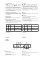
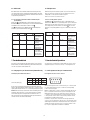
Video Quad- Kanal-An- Funktion
Freeze Taste 5 wahltaste 6
EIN EIN EIN Das Quadrantenbild wird einge-
froren.
EIN AUS EIN Darstellung des eingefrorenen
Bildes im Vollbild-Modus
AUS EIN/AUS EIN Darstellung des Kameraeinganges
im Vollbild-oder Quad-Modus
Video Quad Channel select Function
Freeze button 5 buttons 6
ON ON ON Freeze specic camera video
in quad screen mode
ON OFF ON Call up specic camera input
in Freeze mode
OFF ON/OFF ON Call up specic camera input
in Full screen mode
7 Erdungs - Anschluss
Vorgesehen zum Anschluss der Betriebserde.
8 Spannungsversorgung
Anschluss des mitgelieferten Netzadapters (12VDC)
7 Chassis GND
This contact is provided to ground the chassis to the Earth Ground to prevent
interference and electrical shock.
8 Power Input
Power input connector. Use DC 12VDC

4
5
9 Fernbedienungs-/RS-232 - Anschluss
Anschluss für die jeweils vorgesehene Fernbedienung (s. Abschnitt 8/Zube-
hör), bzw. zur Geräte-Konguration über einen PC (s. Abschnitt 7).
10 Alarm-Eingang (Alarm in)
9-pol. D-Sub-Buchse für den Anschluss der Alarm Ein-/Ausgangs-Kontakte.
Als Alarm-Ausgang ist ein Relais-Umschaltkontakt vorhanden.
Pin - Belegung des Alarmanschlusses
Pin-Nr. Pin-Nr. Pin-Nr.
1 Eingang 1 4 Eingang 4 7 Schliess-Kontakt
2 Eingang 2 5 Reset 8 Gemeinsam
3 Eingang 3 6 Masse 9 Öffner-Kontakt
9 Remote/RS-232 Connector
This 9 pin D-sub connector is used to provide remote control operation via
the appropriate remote keypad (see section 8/Accessories) or a PC.
Please refer to section 7 for more details.
10 Alarm In
This 9 pin D-sub connector is used for alarm sensor input and alarm output
control connections. It provides Normally open and Normally closed contacts
for alarm out control.
Pin assignment for alarm connector
Pin # Pin # Pin #
1 Sensor 1 4 Sensor 4 7 Normally open contact
2 Sensor 2 5 Reset 8 Common contact
3 Sensor 3 6 GND 9 Normally closed contact
11 Eingangs-Abschluss
Impedanz-Schalter für jeden Kamera-Eingang, schaltet zwischen 75Ohm
und HI-Z Impedanz. Ein falscher Abschluss setzt die Qualität des Videosignals
herunter. Der Abschluss ist werkseitig auf 75Ohm gesetzt.
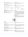
12 Videoeingänge
BNC-Eingänge zum Anschluss der Kameras 1-4.
Im Quad-Modus werden die vier Eingänge wie folgt dargestellt:
11 Terminations
These impedance switches are used to provide proper termination for each
camera input. These switches toggle between 75ohms and Hi-Z impedance.
Incorrect termination will degrade the quality of the video signal. All video
inputs not „looped through” to another device, the corresponding switches
need to be set to 75ohms termination position. If another device is connected
to video out loop through connector, set the corresponding termination
switch to Hi-Z position. Any device connected to the video out loop through
connectors needs to be congure to 75ohms. video termination. The factory
default termination setting is 75ohms.
12 Video IN Connectors
These BNC connectors are used to connect to the video out from camera.
Total four cameras can be connected to form a quad screen in the following
mapping position. It is very important that each camera be correctly termi-
nated. Please refer to Termination (#12) for proper impedance setting for
each video in connector.
13 Video Out
Video out loop through connectors: These connectors are used to loop video
signals from each camera out to other devices.
15 VCR In
This BNC connector is to be connected to the „video out” from your VCR. A
pre-recorded quad screen video can be played back from the VCR and pass
through to be displayed on the Monitor out 17 from this unit. This connector
also allows user to display and program the on screen menu of the connec-
ted VCR without reconnecting the cables.
16 VCR Out
This BNC connector is to be connected to the „video in” from your VCR.
It will only provide a quad screen video to ensure an un-interrupted video
recording for all four cameras. The display video is not affected by the
control panel and alarm status of the unit.
17 Monitor Out
This BNC connector is to be connected to the „video in” of your monitor. It
displays live video from camera inputs under live mode and playback video
from VCR under VCR mode. The live video displayed here can be in quad
screen, full screen, and auto sequencing mode depending on the operation.
1 2
3 4
13 Videoausgang
BNC-Ausgangs-Buchsen zum Duchschleifen der Kamerasignale zu anderen
Geräten.
15 VCR-Eingang (VCR IN)
BNC-Buchse für den Anschluss des Videorecorder-Ausganges. Dies ermög-
licht das Anzeigen und Programmieren des Menüs eines angeschlossenen
Videorekorders.
Durch Betätigen der Taste 3 auf der Frontseite, schaltet man die Geräte auf
die Betriebsart „VCR-Wiedergabe” um.
16 VCR-Ausgang (VCR OUT)
BNC-Buchse für den Anschluss des Videorekorder-Einganges. Es werden
immer alle 4 Kameras aufgezeichnet. Die Aufzeichnung wird von der Bild-
wahl über die Fronttastatur nicht beeinusst.
17 Monitor-Ausgang (LIVE)
BNC-Buchse für den Anschluss an einen Monitor-Eingang zur Wiedergabe
von Live-Bildern. Die Live-Bilder können als Quadbild, Vollbild oder in
sequenzieller Darstellung erfolgen.

6
7
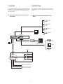
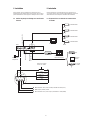
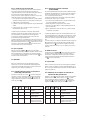
5 Installation Notes
It is essential that your system be properly hooked up for proper results. Use
the following diagram to install your system. Please power-off the unit before
installation.
5.1 Basic System Connection With Alarm Inputs and
Output
Hi-Z
1 2 3 4
DC 12V 1amp
Remote or RS-232
ALARM
in
out
monitor
vcr
ch1 ch2 ch3 ch4
1
6
VCR
Monitor
Processor
Camera 1
Camera 2
Camera 3
Camera 4
VCR
Quad-Darstellung
Quad display monitoring
Monitor
AC Adapter
Alarm reset
sen. 1
sen. 2
sen. 3
sen. 4
NO: Normaly open (Schliesser)
COM: Common (gemeinsam)
NC: Normaly closed (Öffner)
NO
COM.
NC
Video out
to Monitor
Quad
VCR in
to VCR
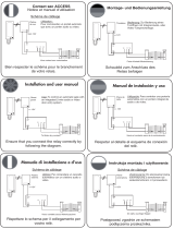
5 Installation
Vor der Installation Ihrer Anlage lesen Sie bitte auch die Betriebsanleitungen
der anderen, für das System vorgesehenen Geräte. Der Quad-Splitter sollte,
erst nach der Verkabelung aller Einheiten, an die Spannungsversorgung
angeschlossen werden.
5.1 Grundsätzliches Verkabelungsschema mit Alarm
Ein-/Ausgang

6
7
1
6
NO
COM
NC
t
Hi-Z
1 2 3
4
DC 12V 1amp
Remote or RS-232
ALARM
in
out
monitor
vcr
ch1 ch2 ch3 ch4
VCR
Recorder SW
COM.
Stop SW
Recorder
SW
Stop
SW
Alarm trigged
start recording
NO ––> NC
Recording stop
COM. (GND or VCC)
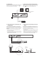
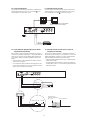
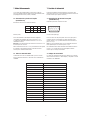
5.3 Videorekorder-Anschluss für Aufzeichnungs- und
Start/Stop-Betrieb
Für den automatischen Aufzeichnungsbetrieb auf einen VCR sind die
Fernsteuerungs-Funktionen „Aufzeichnung” und „Stop” des VCR mit den
Ausgangskontakten des Quad-Splitters zu verkabeln. Die Aktivierung eines
Alarm-Kontaktes löst die VCR-Aufzeichnung für die Dauer des Alarmzu-
standes aus.
• Stehen mehrere Alarme gleichzeitig an, wird das Bild der zuletzt
aktivierten Kamera aufgezeichnet.
• Sollen ausschließlich Vollbilder aufgezeichnet werden, ist der Rekorder-
Eingang mit dem Anschluss LIVE zu verbinden. Es wird jeweils das Bild
der zuletzt aktivierten Kamera aufgezeichnet.
5.3 VCR Connection for Tape Recording Start and Stop
Control
Connecting the contacts of VCR’s RECORD and STOP switch to the alarm
output NC and NO contacts will allow you to use an ordinary VCR to record
for longer period of time. Combined with alarm sensor detection, the VCR
will record only when an alarm sensor is activated.
• If more than one sensor have been trigged, VCR will start to record after
the last trigged event.
• In order to make use of the alarm called full screen display function the
VIDEO IN connector from the VCR has to be connected to LIVE monitor
connector of the device. If more than one sensor are trigged, VCR will
then record all the events in full screen mode accordingly.
5.2 VCR-Wiedergabe
VCR-Wiedergabebetrieb, zur Darstellung und Vergrößerung aufgezeichneter
Quad-Bilder (Zoom-Funktion). Durch Betätigung der VCR-Taste 3 auf der
Frontseite der Geräte gelangt man in diesen Modus.
5.2 VCR Connection for Zoom on Playback Operation
VCR playback mode is designed to play pre-recorded quad screen video and
display in either quad screen or expand any quadrant to full screen. Push
VCR button 3 in the front panel to switch to VCR playback mode.
hi-z
1 2 3
4
DC 12V 1amp
RS-232
ALARM I/O
in
out
monitor
vcr
Video in
Video out
Video in
Video out
Quad-Bild / Quad display 2fache Vergrößerung für jeden Quadranten /
2x expansion for any quadrant
VCR
AC Adapter

8
9
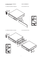
5.4 Montage der Einschub – Winkelsets
Siehe auch Abschnitt 8/Zubehör
5.4 Use of Rack Mount Kit
1/2 19" Winkelset für den Einbau eines Einzelgerätes 1/2 19" Rack mount kit for one unit
1x
1x
4x
2x
2x
14x
1/2 19" Winkelset für den Einbau von zwei Geräten 1/2 19" Rack mount kit for two units

8
9
1 2
3 4
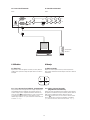
5.5 Fernsteuerungs - Anschluss
Rückfront
5.5 Remote Control Connection
Rear panel
hi-z
1 2 3
4
DC 12V 1amp
RS-232
ALARM I/O
in
out
monitor
vcr
Fernbedienung /
Remote keypad
6 Bedienung
6.1 Bildschirm-Menü
Nach dem Einschalten des Gerätes zeigt der Monitor (Anschluss 17) die ak-
tuellen Einstellungen. Der Monitor zeigt die Bilder der vier angeschlossenen
Kameras im Quad-Modus.
6 Operating
6.1 The Setup Menu
Right after the unit is turned on, monitor connector 17 on the rear panel will
display the last setting on the setup menu. The Monitor always displays
4 cameras in quad screen mode as follows:
^
^
^
^
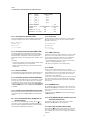
6.1.1 Seite 1 des Bildschirm-Menüs
(Anzeige-Programmierung)
Es können zwei Menü-Seiten angewählt werden.
Seite 1 ist für die Programmierung von Verweildauer, Uhrzeit/Datum und
Kameratitel vorgesehen, Seite 2 für die Konguration der Alarmverarbeitung.
Mittels der Anwahltasten 6 wird der Cursor bewegt und die Selektion der
Textzeichen vorgenommen. Zum Bewegen des Cursors werden die mit den
Zeichen < und > gekennzeichneten Tasten benutzt, für die Auswahl der
Textzeichen die Tasten „ ” und „ ”.
6.1.1 Page 1 of the Setup Menu (Display Setting)
There are two pages in the Setup Menu.
Page 1 is used to program DWELL TIME, TIME, DATE, camera TITLE, and
other display settings. Page 2 is used to program Alarm Operations.
Under this mode, channel selection buttons 6 on the front panel are used
for cursor control and text selection. Use the cursor control buttons „<” and
„>” to move the cursor to the entry in the menu desired to program, and
use the text select buttons „ ” and „ ” to choose the right alphanumeric
character to program.

10
11
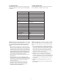
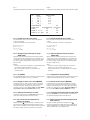
Seite 1:
Programmierung von Zeit/Datum/Kameratitel und Bild-Intervallzeit
CH TITLE DWELL TIME
QUAD 03 S
1 __CH _1_ 03 S
2 __CH _1_ 03 S
3 __CH _1_ 03 S
4 __CH _1_ 03 S
VIDEO FREEZE ON
VIDEO OUT:
LIVE/MONITOR
QUAD/VCR
TITLE: ON ON
TIME: 08 : 10 : 10 ON ON
DATE: 04 –01 - 2000 ON ON
6.1.1.1 TITLE Setup
The title menu permits the setup of separate titles for each video channel.
Eight characters may be entered for each video channel. The available
alphanumeric characters are:
0, 1, 2, 3, 4, 5, 6, 7, 8, 9, ...
A, B, C, D, ... X, Y, Z
a, b, c, d, ... x, y, z
:, <, >, -, x, /, ?, space.
6.1.1.2 DWELL Time Setup
The Dwell time menu permits setting the dwell time for all cameras and the
quad screen on the Live output channel. The menu shows a table of all
cameras and associated dwell time. Dwell time can be programmed by
setting a number between 00 to 99 for each channel in the menu.
• -01 through 99: Adds the camera input to the auto switching sequence,
with the corresponding dwelll time in seconds
• -00: Skips the camera input in the auto switching sequence.
6.1.1.3 FREEZE
This entry is used to enable or disable the video freeze operation.
1. If this entry is set to ON, user can freeze the specic camera video under
live quad display mode by pressing corresponding channel buttons on the
front panel. However, user can only call up specic camera if the unit is
operated under full screen display mode.
2. If this entry is set to OFF, there will be no video freeze function. Under this
mode, the unit will only call up specic camera in live full screen display
by pressing corresponding channel buttons regardless the original display
mode of the unit.
6.1.1.4 TIME/DATE Setup
Time and date information can be displayed on the video output channel
through both Live and Quad connector. Bottom of page 1 is used to set the
values of time and date and also to enable or disable the display at each
output channel.
The time will display in the HH:MM:SS format and the date will display in
the MM-DD-JJ-Format.
6.1.1.5 TITLE/TIME/DATE Disable and Enable in Live and
Quad Video Output Channel
The title/time/date display on each output channel can be enabled or
disabled by setting ON or OFF in the corresponding entry.
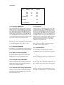
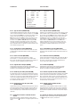
6.1.2 Page 2 of the Setup Menu (Alarm Setting)
Push setup buttons 2 simultaneously again to display page 2 of the setup
menu on the screen. This alarm setting menu is used to set the desired
alarm conguration like sensor type, sensor sensitivity, alarm hold duration
and buzzer.
6.1.1.1 Einstellung des Kameratitels (TITLE)
Für jeden Kamera-Kanal kann eine bis zu 8-stellige Bezeichnung eingegeben
werden. Die verfügbaren Zeichen sind in der folgenden Tabelle gezeigt:
0, 1, 2, 3, 4, 5, 6, 7, 8, 9, ...
A, B, C, D, ... X, Y, Z
a, b, c, d, ... x, y, z
:, <, >, -, x, /, ?, space.
6.1.1.2 Einstellung der Bild-Intervallzeit (DWELL TIME)
Einstellung der Bild-Intervallzeit (Verweildauer) für jeden Kamera-Kanal
sowie des Quadbildes im automatischen Umlauf, für den Monitor-Ausgang.
Das Bildschirm-Menü zeigt die Nummern aller Kamera-Kanäle und die
dazugehörige Verweildauer, die zwischen 00 bis 99 sek. eingegeben werden
kann.
Einstellungen:
• -01 bis 99: Kamera-Kanal ist im automatischen Umlauf enthalten, das Bild
wird für die angezeigte Dauer (in Sek.) wiedergegeben.
• -00: Kamera-Kanal wird im automatischen Umlauf nicht berücksichtigt
(übersprungen).
6.1.1.3 Einfrieren (FREEZE)
Bei Stellung EIN kann das aktuelle Bild im Vollbild- oder Quad-Betrieb einge-
froren werden. Bei Stellung OFF ist die Funktion „Einfrieren“ deaktiviert.
6.1.1.4 Einstellung von Uhrzeit und Datum (TIME/DATE)
Die Anzeige von Uhrzeit und Datum kann sowohl auf dem Monitor eingeblen-
det werden. Der untere Bereich des Bildschirm-Menüs ist für die Eingabe
der Zeit/Datums-Information sowie auf welchem Monitor die Wiedergabe
erfolgen soll, vorgesehen. Die Anzeige erfolgt im Format: Stunden : Minuten
: Sekunden (HH:MM:SS) für die Uhrzeit und Monat-Tag-Jahr (MM-DD-JJ)
für das Datum.
6.1.1.5 Anzeige von Uhrzeit/Datum/Kameratitel Ja/Nein
Ob und auf welchem Ausgang die einzelnen Anzeigen eingeblendet werden
sollen, wird durch das Setzen von ON, bzw. OFF für jeden Ausgangs-Kanal
bestimmt.
6.1.2 Seite 2 des Bildschirm-Menüs (Konguration der
Alarmverarbeitung)
Um auf die Seite 2 des Bildschirm-Menüs zu gelangen die Taste 2 be-
täti-gen. Diese Seite ist für das Kongurieren der Alarmverarbeitung, wie
Kontakt-Typ, Ansprech-Empndlichkeit, Alarmdauer, akustische Alarmgabe,
Videoverlustalarm und Videoverlustrelais vorgesehen.

10
11
6.1.2.1 Kontakt-Typ (SENSOR TYPE)
Das Gerät erkennt selbsttätig die Art des an jedem Kanal vorhandenen
Kontakt-Typs. Das Resultat wird in der Tabelle für jede Kanal-Nr. angezeigt:
OPEN für Schließkontakt-, CLOSE für Öffnerkontakt-Typ. In der nächsten
Spalte der Tabelle kann ein gewünschter Kontakt-Typ je Kanal eingegeben
werden. NO steht dabei für Schließkontakt, NC für Öffnerkontakt. In der
darauffolgenden Spalte wird eingegeben, ob der jeweilige Kontakt in die
Alarmverarbeitung einbezogen werden soll, oder nicht (STATUS). ON steht
für eine Einbeziehung, OFF unterdrückt sie. Die letzte Spalte zeigt, ob der
gewünschte Kontakt-Typ mit dem tatsächlich vorhandenen übereinstimmt.
Ist dies nicht der Fall, wird in der betreffenden Zeile ein blinkendes ? gezeigt
und beim Verlassen der Menü-Seite ertönt ein akustisches Signal.
6.1.2.2 Ansprech-Empndlichkeit (SENSITIVITY)
Das Gerät reagiert nur dann auf eine Alarmauslösung, wenn die Kontaktgabe
für eine bestimmte, einstellbare Zeitdauer erfolgt.
Eine Einstellung kann zwischen 0,2; 0,3; 0,4 und 0,5 sek. erfolgen.
6.1.2.3 Alarmhaltezeit (DURATION)
Die Alarmdauer kann zwischen 00 sek. bis 99 min. eingestellt werden.
Durch Anwahl von „>>” kann die Alarmdauer auf unendlich gesetzt werden.
In dieser Betriebsart kann ein ausgelöster Alarm nur durch Verbindung des
Alarm-Rücksetzkontaktes mit Masse zurückgesetzt werden.
6.1.2.4 Akustische Signalisierung (BUZZER)
Das Gerät verfügt über einen eingebauten Signalton-Geber, um einen
detektierten Alarm akustisch zu signalisieren. Im Feld BUZZER kann diese
Alarmsignalisierung durch Setzen auf OFF unterdrückt werden.
6.1.2.5 Videoausfall-Alarm (V-LOSS ALARM)
Mit dieser Einstellung kann die Signalisierung eines Videosignalausfalls
aktiviert oder deaktiviert werden. Das Gerät detektiert automatisch jeden
Videosignalausfall an jedem Eingang, wenn diese Option auf ON steht. Der
Anwender kann diese Funktion durch Einstellung auf OFF deaktivieren, um
Anwendungen zu ermöglichen, die eine ständige Videoquellenumschaltung
erfordern, wie z. B. Videokonferenz-Schaltungen.
6.1.2.6 Videoausfall-Relaissteuerung (V-LOSS RELAIS)
Das Gerät verfügt über ein alarmgesteuertes Relais, das sowohl durch
Alarmauslösungen von einem Sensor, wie auch durch Videoausfallalarm
aktiviert werden kann. In dieser Einstellung kann vom Benutzer die Akti-
vierung des Relais durch einen Videosignalausfall an einem beliebigen
Kameraeingang deaktiviert werden.
6.1.2.1 Sensor Type
The unit will rst detect the type of the sensor connected to the corres-
ponding channel. The result will be displayed in the rst column following
each channel number. They can be on either OPEN or CLOSE. The menu
then allows user to enter a desired type of the sensor for each channel in
next column. NO means Normally Open, NC means Normally Close. Then the
menu will allow user to enable or disable sensor input for each channel in
the next column. ON will enable the contact to detect the alarm status from
the input. OFF will ignore the sensor input and disable the alarm detection
from the input. Last column on this part of the menu shows the result of the
actually detected sensor type and the desired conguration. If the setup type
of the sensor is different from the actually connected type of sensor, a
blinking ? message will be displayed. In this case, the buzzer will be
activated when you exit the setup operation.
6.1.2.2 Alarm Sensitivity
Alarm sensitivity can be programmed to different extent by setting the
period of the triggered pulse detected by the sensor.
The available settings are from 0.2; 0.3; 0.4 to 0.5 sec.
6.1.2.3 Alarm Hold Duration
The alarm hold duration can be set from 0 second to 99 minutes.
The duration can be set to non-stop by choosing „>>”. In this mode, the
activated alarm can only be reset by connecting the alarm reset contact to
ground.
6.1.2.4 Buzzer
The device has a built-in buzzer to signal a detected alarm by an audio tone.
User can choose to disable the buzzer by setting it to OFF.
6.1.2.5 Video Loss Alarm
This entry is used to enable or disable the video loss alarm. The device auto-
matically detects loss of video at any input if this entry is set to ON. User can
choose to disable this feature by setting it to OFF for applications like video
conferencing or others that will need constant video source switching.
6.1.2.6 Video Loss Relais
The device is equipped with an alarm controlled relay, which can be acti-
vated by both sensor trigged alarm and video loss alarm. This entry allows
user to disable the relay activation from a loss of video in any camera input.
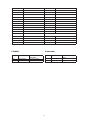
CH SENSOR TYPE STATUS
1 OPEN NO ON?
2 OPEN NO ON?
3 OPEN NO ON?
4 OPEN NO ON?
SENSITIVITY: 0.3 S
DURATION: 30 S
BUZZER: ON
V-LOSS ALARM: ON
V-LOSS RELAY: ON
ALARM SETTING

12
13
6.1.3 Sicherung der Eingaben und Verlassen des
Bildschirm-Menüs
Zum Abspeichern der Einstellungen und zum Verlassen des Einstellungs-
modus: Drücken Sie erneut die Taste 2 , um die Einstellungen abzuspei-
chern und den Einstellungsmodus zu verlassen.
6.1.4 Werkseitige Einstellungen
Systemeinstellungen können auf die werkseitigen Grundeinstellungen
zurückgesetzt werden, indem die Lock-Taste 2 und die VCR-Taste 3 beim
Einschalten des Gerätes gedrückt gehalten wird, bis die 4-fach Darstellung
auf dem Bildschirm erscheint.
6.2 Quad-Darstellungs-Modus
6.2.1 Die Quad-Taste 5 bestimmt die Quadbild-Wiedergabe auf dem
Monitorausgang. Nach dem Einschalten des Gerätes erscheint sofort die
Quadbild-Darstellung.
6.2.2 Im Bildschirm-Menü Nr. 1 wird bestimmt, ob der Kameratitel je Kanal
sowie die Uhrzeit- und Datumsanzeige im Live-, bzw. Quad-Monitorbild
eingeblendet werden soll.
6.2.3 Im Quadbild-Modus können die einzelnen Quadrantenbilder, durch
Betätigung der jeweiligen Kamera-Anwahltasten, „eingefroren” werden.
6.3 Vollbild - Darstellung
6.3.1 Anwahl der Kamera-Eingänge mit den Tasten 6 bei ausgeschaltetem
Quad-Betrieb.
6.3.2 Durch erneutes Drücken der Taste 5 gelangt man in den Quadbild-
Modus zurück.
6.4 Standbild-Darstellung der Kamerabilder (FREEZE)
6.4.1 Zum „Einfrieren” der Bilder in den einzelnen Quadranten wird zunächst
der Quad-Modus angewählt (Taste 5 ). Durch Drücken der Anwahltasten 6
werden die jeweiligen Quadranten als Standbilder gezeigt.
6.4.2 Bei der VCR-Wiedergabe von aufgezeichneten Quad-Bildern kann
mittels der Kanal-Anwahltasten 6 das jeweilige Quadrantenbild auf Vollbild
vergrößert werden. Ein Einfrieren des vergrößerten Quad-Bildes kann man
durch erneute Betätigung der gleichen Kanal-Taste bewirken.
6.1.3 Save the Settings and Exit Setup Menu Mode
Push the button 2 again will allow you to choose to save the settings or not
by using the up or down arrows. Push the button 2 fourth time to go back
to the normal operation mode and show a quad display on the screen.
6.1.4 Factory Default Settings
The system setup can be reset to factory default by pushing and hold Lock
2 and VCR 3 buttons down and power on the unit simultaneously until the
quad display shows up on the screen.
6.2 The Quad Display Mode
6.2.1 Push quad display button 5 to switch to quad screen display mode.
Right after you turn on the system, the unit is in the quad mode and displays
cameras 1-4.
6.2.2 Use page 1 of the setup menu to turn the title display ON/OFF in each
channel and also enable and disable the time and date display on Live and
Quad output channels.
6.2.3 Under quad screen mode, push channel select button to freeze each
camera input.
6.3 The Full Screen Display Mode
6.3.1 Under this mode, you may call up any specic channel in full screen
by simply pushing the corresponding channel selection button, when Quad
mode is off.
6.3.2 Push the quad display button 5 to ON to return to the quad mode.
6.4 The still frame display mode (FREEZE)
6.4.1 If the still screen mode is desired, rst turn the quad display button 5
to ON to set the unit to display in the quad mode. At this time you may press
any of the four channel selection buttons 6 to freeze the corresponding
channel.
6.4.2 For Zoom on VCR playback mode, if the unit is showing quad screen,
pushing the channel selection buttons 6 will call up the specic channel
to display in full screen. Push the same channel selection button again to
freeze that channel in full screen display.

12
13
6.5 Alarm Einstellungen
6.5.1 Aktivierung von kontaktgesteuerten - und Video-
ausfall-Alarmmeldungen.
6.5.1.1 Alarmauslösung durch Alarmkontakte
Das Gerät verfügt über Alarmsensor-Eingänge entsprechend der Anzahl der
Kameraeingänge. Bei Auslösung eines beliebigen Alarms wird folgender
Ablauf gestartet:
1. Wenn die Videoausfall-Relaissteuerung auf ON steht, werden die
akustische Alarmsignalisierung und das Alarmrelais ausgelöst.
2. Die entsprechende LED-Kanalanzeige blinkt.
3. Auf dem Monitorausgang 17 wird das Videosignal der alarmauslösenden
Kamera in Vollbilddarstellung wiedergegeben.
Zusätzlich wird eine ALARM-Warnmeldung und der Titel der Kamera ein-
geblendet. Gleichzeitig wird dieselbe Meldung auf dem Videorekorder-
Ausgang in 4-fach Darstellung ausgegeben.
Die Zurücksetzung eines durch einen Sensor ausgelösten Alarms kann durch
folgende Möglichkeiten erfolgen:
1. Verbinden Sie den Alarmrücksetz-Kontakt, PIN Nr. 5 der 9-poligen D-SUB-
Buchse 10 mit Masse.
2. Ende der Alarmverweildauer.
6.5.1.2 Videoausfall-Alarm (V-LOSS ALARM)
Im Bildschirmmenü kann der Videoausfallalarm aktiviert oder deaktiviert
werden, um Anwendungen, die eine häuge Umschaltung der Videoquellen
benötigen (z. B. Videokonferenzen) zu ermöglichen. In Kapitel 6.1.2 nden
Sie hierzu detaillierte Anweisungen.
Wenn die Videoausfall-Funktion aktiviert ist und der Ausfall eines Videosig-
nals detektiert wird, erfolgt folgender Ablauf:
1. Wenn die Videoausfall-Relaissteuerung auf ON steht, werden die
akustische Alarmsignalisierung und das Alarmrelais ausgelöst.
2. Die entsprechende LED-Kanalanzeige blinkt.
3. Zur Kenntlichmachung des Alarms wird das letzte Bild vor dem Video-
ausfall eingefroren.
4. Abwechselnd werden die „Video Loss”-Meldung und der entsprechende
Kameratitel auf dem Bildschirm eingeblendet.
Wenn der Videoausfallalarm deaktiviert ist, stellt das Gerät nur einen leeren
Bildschirm ohne jegliche Meldung oder andere Hinweise dar, wenn ein
Videoausfall erfolgt. Dies ermöglicht Anwendungen, die eine häuge
Umschaltung von Videoquellen ohne Auslösung eines Warnsignals erfordern.
Wenn das Gerät mit eingeschalteter Sicherheitssperre (Security Lock ON)
betrieben wird, können die Warnmeldung und die akustische Signalisierung
durch Drücken der Lock-Taste 2 für mehr als 2 Sekunden abgeschaltet
werden. In Stellung Security Lock OFF kann die Rücksetzung durch jede
beliebige Taste auf der Vorderseite des Gerätes erfolgen.
6.6 Sequenzieller Umlauf
Die Betätigung der Taste 4 Sequence startet die sequenzielle Darstellung
aller anliegender Kamera-Signale. Bei dieser Betriebsart wird zuerst das
Quad-Bild und dann folgend alle anderen Signale von 1 bis 4, im vorein-
gestellten Zeittakt gezeigt. Ein erneutes Drücken der Taste 4 hebt die
Betriebsart wieder auf.
6.5 Alarm Operations
6.5.1 Alarm Operations: Sensor Activation and Video Loss
6.5.1.1 Sensor Activated Alarm
The device is equipped with 1 alarm sensor contact for each camera input.
If any alarm is activated the device will:
1. Activates the built-in buzzer and also the alarm output relay if the V-Loss
Relay Control is set to ON.
2. Switches the corresponding channel indicator LED to blinking mode
3. Displays and overlays ALARM warning message and the title of the
camera alternately on the activated camera through Monitor out 17 video
in full screen mode. In the mean time, same message will be displayed
on VCR out video in quad screen mode.
The sensor activated alarm can be cleared by any of the following:
1. Connecting the Alarm Reset In contact, pin 5, of the female 9 pin D-sub
connector 10 to GND.
2. The Alarm Duration time elapses.
6.5.1.2 Video Loss Alarm
Video loss alarm feature can be enabled or disabled in the on screen menu
to setup the device for applications like video conference, which require a
constant video source switching. Please refer to Sec. 6.1.2 for more detail.
When video loss alarm feature is enabled and any loss of video is detected,
this device will:
1. Activates the built-in buzzer and also the alarm out relay if the V-Loss
Relay Control is set to ON.
2. Switches the corresponding channel LED to blinking mode.
3. Freezes the last picture before the loss of the video for alarm
documentation.
4. Displays „Video Loss” message and the corresponding camera „Title”
alternately on the screen.
If the video loss alarm feature is disabled, the device will simply display
blank screen without any message and any other acknowledgement action
if any loss of video is detected. This is to allows applications that require
video source switching without any warning signal.
The warning message and the buzzer can be cleared by pushing Lock
button 2 for more than 2 seconds if the device is operated under Security
lock ON mode, or push any button on the front panel if the device is
operated under Security lock OFF mode.
6.6 The Auto-Sequence Mode
Push the sequence button 4 to ON to set the device to work as a
sequencer. Under this mode, the display sequence rst starts with a quad
screen, then continues to display each camera input in full screen and then
gets back to quad screen and so on. Press the sequence button 4 to OFF
to release this mode.

14
15
6.7 VCR Operations
6.7.1 Connecting the Record and Stop switch connectors from a VCR to the
alarm out contact in the 9-pin D-sub connector will allow user to use an
ordinary VCR to record only when an alarm is triggered.
Please refer to section 5.3 for detail connection.
6.7.2 Zoom on VCR playback operation
Push VCR button 3 to ON will switch the device to VCR playback mode.
Under this mode, if the device is on quad display mode, a pre-recorded quad
display video in the tape will be shown on the screen. If the device is in full
screen display mode, push any channel select buttons 6 will select and
expand the corresponding quadrants of the pre-recorded video to full screen
display.
6.7 VCR-Betrieb
6.7.1 Der Anschluss der Fernbedien-Funktionen Aufzeichnung und Stop
eines Videorekorders an den Schaltausgang des Quad-Splitters ermöglicht,
dass der Rekorder automatisch das Bild einer alarmierten Kamera aufzeich-
net (Verkabelung s. Abschnitt 5.3).
6.7.2 Vergrößerung der Quadranten-Bilder bei VCR-Wiedergabe
(Zoom-Funktion)
Mit der Taste 3 auf VCR-Wiedergabe schalten und das aufgezeichnete
Quad-Bild wiedergeben. Voraussetzung für ein Zoomen der Quadrantenbilder
auf Vollbild-Format ist die Betriebsart „Vollbild”, Taste 6 .
Taste 5 . Die Auswahl, welches Quadrantenbild als Vollbild dargestellt
werden soll, geschieht mit den Anwahl-Tasten 6 .
VCR-Taste 7 Quad-Taste 5 Kanaltasten 6 Funktion
EIN EIN AUS Darstellung des
aufgezeichneten
Quadbildes
EIN AUS 1x Vergrößerte
Quadrantenbild-
Darstellung
EIN AUS 2x Einfrieren des
vergrößerten
Quadrantenbildes
AUS X X VCR-Wiedergabe
über das Gerät
beenden, Rückkehr
in die zuvor ange-
wählte Betriebsart
VCR button Quad button CH select button Function
7 5 6
ON ON OFF Display quad
video signal from
VCR tape
ON OFF Push once Call up specic
quadrant from
tape in full screen
mode
ON OFF Push twice Freeze specic
quadrant from
tape in full screen
mode
OFF X X Exit VCR operation,
back to normal
operating mode
7 Fernbedienbetrieb
Über den 9-pol. D-Sub Fernbedien-Anschluss 9 (Remote or RS-232) kann
das Gerät mittels einer Kabel-Fernbedienung (s. Abschnitt 8/Zubehör) oder
eines PC’s ferngesteuert werden (ASCII-Code).
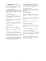
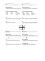
7.1 Belegung der 9-pol. D-Sub-Buchse (Remote/RS-232)
Pin-Belegung des Fernbedien-Anschlusses
Steckerseite (Male type)
Bei den, zu den jeweiligen Geräte-Modellen passenden Kabel-Fernbedie-
nungen (s. Abschnitt 8/Zubehör), werden über die Pins 1, 2 und 3 die Steuer-
signale geführt und über die Pins 5, 6, 7, 8 und 9 die Spannungsversorgung.
Hinweis: Wird zur Steuerung ein PC benutzt, unter Verwendung der RS-232-
Schnittstelle, dürfen die Pins 6, 7, 8 und 9 nicht angeschlosssen werden.
Für die Übertragung der Steuersignale sind ausschließlich die Pins 1, 2
und 3 zu benutzen. Über die Fernbedienung sind die gleichen Funktionen
steuerbar, wie über die normale Frontbedienung.
7 Remote Control Operations
The device may be controlled via the 9 pin D-sub/RS-232 connector from a
appropriate keypad (see section 8/accessories), or a PC using ASCII code.
7.1 Pin Assignment of the 9 pin D-Sub Connector
Pin assignment for remote control connector
When a remote keypad is used to control the device, pin 1, 2 and 3 are used
for control signals transmission, pin 6, 7, 8 and 9 are used for providing
power to the remote keypad.
Note: If a computer device is used to control this unit through a RS-232 port,
pin 6, 7, 8 and 9 must be disconnected to prevent connecting the Vcc and
GND signals from the device to the computer. A RS-232 port only uses pin
1, 2 and 3 for control signal transmission. If a remote keypad is connected
to the 9 pin D-sub connector, all the control functions provided in the front
panel will be also available from the keypad.
A terminal or computer can be connected to the male type 9 pin D-sub
connector on the rear panel from it’s RS-232 port to control this device using
standard uppercase ASCII codes. The ASCII command codes for the quad are
available upon request. The interface protocol consists of 8 data bit, 1 start
bit, 1 stop bit, no parity and the transmission is 1200 baud.
1 GND 4 NC 7 VCC
2 RX 5 NC 8 GND
3 TX 6 VCC 9 GND
5
9
1
4
8
3
7
2
6

14
15
Funktion/Function ASCII Steuercodes/ASCII Command Code
Gerätetyp/Model VCQ-6056 and VBQ-6044
Quad Screen Display E
CH1 A
CH2 B
CH3 C
CH4 D
Freeze *1 EA, EB, EC, ED
Zoom *1 –
Auto Switching Sequence F
Buzzer ON/OFF Any ASCII Command Code
VCR/ Live *2 G
Key Lock *3 H
Setup Menu *4 GH
Text Select Down *5 (GH) A
Text Select Up (GH) B
Cursor Left (GH) C
Cursor Right (GH) D
Alarm Reset I
Beispiel: Durch Eingabe von GE, (GE)B, (GE)C und (GE)D werden die Signale
1 bis 4 des Videorekorders gezoomt. Die Eingabe von „A”, „B”, „C” und „D”
friert den entsprechenden Kanal ein. Durch Eingabe des Kommandos „G”
wird zwischen Videorekorder-Wiedergabe und Live-Wiedergabe umge-
schaltet.
*1 Damit das Gerät im Zoom-Modus gesteuert werden kann, muss der
Computer zuerst das Steuerkommando „G” senden, um die Signalquelle
von Kamera auf Videorekorder umzuschalten. In diesem Moment wird
automatisch der Kanal 1 des Videorekorders auf die gesamte Bildgröße
gezoomt. Vom Bediener kann dann ein entsprechender Kanalcode ein-
gegeben werden, um einen anderen Kanal zu zoomen. Durch erneute
Eingabe des Kanalcodes wird der entsprechende Bildausschnitt einge-
froren und durch nochmalige Eingabe wieder freigegeben.
*2 Das Steuerkommando „G” schaltet zwischen Videorekorder- und Live-
Eingangssignal um.
*3 Um das Gerät zwischen der „Security lock ON und OFF”-Funktion
umzuschalten, muss der Computer für 2 Sekunden ununterbrochen das
Steuerkommando „H” senden. Um einen ausgelösten Alarm zu löschen,
muss das Steuerkommando „H” ununterbrochen für mindestens
6 Sekunden gesendet werden.
*4 Das Setup-Menü wird durch gleichzeitiges Senden der Steuer-
kommandos für die Videorekorder- und die Sperrtaste aktiviert.
*5 Textauswahl- und Cursorsteuerungsfunktionen können nur im
Einstellungsmenü-Modus durchgeführt werden.
Example: Input GE, (GE)B, (GE)C , and (GE)D for zooming the video signal in
channel 1 to 4 from VCR. Input „A”, „B”, „C”, and „D” again to freeze the
specic channel. Send command code „G” again to get back to Live input
mode.
*1 In order to control the device to operate in Zoom mode, the computer
has to rst send command code „G” to switch the signal source from
camera to VCR, at this time the device will automatically zoom channel 1
video from VCR to full screen. User can then input a corresponding
channel code to room any other specic channel. Input the corres-
ponding channel code again to put tile specic channel to freeze mode
and send the code again to clear the freeze mode.
*2 Command code „G” is used to switch between VCR and Live input.
*3 Computer has to send out command code „H” continuously for
2 seconds to switch the device between security lock ON and OFF mode.
If any alarm is activated, under security lock on mode, the device has to
send out command code „H” continuously for more than 6 seconds to
clear the alarm.
*4 Setup menu is switched ON by sending VCR and Lock button codes
together.
*5 Text Select and Cursor Control functions can be performed only under
menu Setup mode.
7.2 ASCII Steuercodes
Die ASCII Steuercodes sind in der Tabelle beschrieben. Das Übertragungs-
protokoll enthält 8 Daten Bits, 1 Start und 1 Stop Bit, die Übertragungsrate
ist 1200 Baud.
7.2 ASCII Command codes
The ASCII Command codes are listed in the table below. The transmission
protocol is 1200 baud rate, 8 databits, 1 start bit, 1 stop bit.

16
17
8 Zubehör
8 Accessories
Status Code Quad Status Status Code Quad Status
EF Device in Quad mode DE CH1 in Sequence mode
EE CH1 in Freeze mode DD CH2 in Sequence mode
ED CH2 in Freeze mode DB CH3 in Sequence mode
EC CH1 & 2 in Freeze mode D7 CH4 in Sequence mode
EB CH3 in Freeze mode CF Quad display in Sequence mode
EA CH1 & 3 in Freeze mode
E9 CH2 & 3 in Freeze mode E CH1 in Full screen mode
E8 CH1, 2 & 3 in Freeze mode D CH2 in Full screen mode
E7 CH4 in Freeze mode B CH3 in Full screen mode
E6 CH1 & 4 in Freeze mode 7 CH4 in Full screen mode
E5 CH2 & 4 in Freeze mode
E4 CH1, 2 & 4 in Freeze mode
Attach to above code
E3 CH3 & 4 in Freeze mode XX-DF Buzzer/VCR ON
E2 CH1, 3 & 4 in Freeze mode XX-7F Security look ON
E1 CH2, 3 & 4 in Freeze mode XX-3F Buzzer & Security lock ON (Stop)
E0 CH1, 2, 3 & 4 in Freeze mode
EDV-Nr. Typ Beschreibung für Quad
Splitter-Modell
72556 VQ6057/6045RMK1 1x VCQ-6057, VBQ-6045
72557 VQ6057/6045RMK2 2x VCQ-6057, 2x VBQ-6045
EDP No. Type Description for Quad Splitter
Model
72556 VQ6057/6045RMK1 1x VCQ-6057, VBQ-6045
72557 VQ6057/6045RMK2 2x VCQ-6057, 2x VBQ-6045

16
17
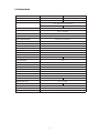
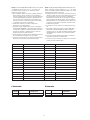
Typ VCQ-6057 VBQ-6045
EDV-Nr.
72614 72613
Signalverarbeitung
Farbe S/W
Videoeingänge
4 x 1Vss, 75Ohm, BNC-Durchschleifeingänge
PAL CCIR
VCR-Eingang
1Vss, 75Ohm
Videoausgänge
Live-Monitor: 1Vss, 75Ohm, BNC
VCR: 1Vss, 75Ohm, BNC
Videosignal-Abschluss
75 Ohm / Hi-Z, wählbar für jede Kamera
Kameratitel
8 Zeichen
Uhrzeit- /Datumseinblendung
Eingebaute Uhr, batteriebetrieben
Alarmeingänge
Schließer-/ Öffnerkontakt
Alarmarten
Videoausfall, Kontaktauslösung
Alarmkontakt-Eingang
4x Alarm-Kontakt
Alarm-Ausgang
NO und NC, 24VDC/1A
Einstellbare Alarmhaltedauer
Ja, Menü
Einstellbare Bildintervallzeit
Ja, Menü
Refresh-Rate
50
Auösung (Pixel)
1024 x 625 720 x 625
Grau-/ Farbabstufung
16,7 Mio.
Videopegel-Einstellung Automatisch
Akustische Alarmsignalisierung
Ja
Fernbedien-Eingang
RS-232, max. Entfernung: 300m
Flacker-Filter
Ja
Zoom-Funktion
Nein
Tastatursperre
Ja
Betriebsspannung
12VDC
Leistungsaufnahme
10W 4W
Abmessungen (H x B x T)
44,1 x 215 x 200mm
Gewicht
2,5kg 2,0kg
Betriebstemperatur
0°C bis +50°C
Netzanschluss-Adapter
230VAC Eingang, 12VDC Ausgang
Einbaufähigkeit
Als 1/2 19”-Einschub (mit optionalem Montagesatz)
9 Technische Daten

18
19
Technische Änderungen vorbehalten.
Technical changes reserved.
© Copyright by VIDEOR TECHNICAL 04/06
eneo
®
ist eine eingetragene Marke der Videor Technical E. Hartig GmbH
Vertrieb ausschließlich über den Fachhandel.
eneo
®
is a registered trademark of Videor Technical E. Hartig GmbH
Exclusive distribution through specialised trade channels only.
VIDEOR TECHNICAL E. Hartig GmbH
Carl-Zeiss-Straße 8 · 63322 Rödermark/Germany
Tel. +49 (0) 6074 / 888-0 · Fax +49 (0) 6074 / 888-100
www.videortechnical.com
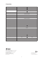
9 Technical Data
Type VCQ-6057 VBQ-6045
EDP No.
72614 72613
Camera Type
Colour B/W
Video Format
4 x 1Vp-p, 75ohms, BNC loop-through
PAL CCIR
VCR Play Back Input
1Vp-p, 75ohms
Video Outpu
Monitor: 1Vp-p, 75ohms, BNC
VCR: 1Vp-p, 75ohms, BNC
Camera Terminations
75ohms / Hi-Z, selectable for each camera
Camera Title
8 characters
Time/Date
Built-in clock with back-up battery
Alarm Sensor Input Type
Normal Open / Normal Close
Alarm Types
Video loss and alarm sensor contact detection
Alarm Sensor Input
Contact closure activated alarm input x4
Alarm Control Output
NO and NC contacts, 24VDC/1A
Adjustable Alarm Duration
Yes
Camera Dwell Time
Yes
Refresh Rate
50
Resolution (pixels)
1024 x 625 720 x 625
Number of Colour
16.7 Mio.
Video Gain Adjustment
Automatic
Buzzer ON/OFF SW Yes
Remote Control/RS-232
RS-232, max. distance: 300m
Flickerless Filter
Yes
Zoom function
No
Security Lockout
Yes
Operating voltage 12VDC
Power Consumption
10W 4W
Dimension (H x W x D)
44,1 x 215 x 200mm
Weight
2.5kg 2,0kg
Operating Temperature
0°C to +50°C
Power Adapter
230VAC input, 12VDC output
Rack Mountable
1/2 19” slot with optional mounting kit

18
19
Sommaire
1 Consignes de sécurité et d’entretien...............................................19
2 Accessoires faisant partie de la fourniture.....................................20
3 Spécications techniques ...............................................................20
4 Position et fonction des éléments de contrôle................................20
A Avant ..........................................................................................20
B Arrière ........................................................................................21
5 Installation........................................................................................23
5.1 Schéma de câblage de base avec Entrée/Sortie Alarme ..............23
5.2 Raccord magnétoscope...............................................................24
5.3 Raccordement du magnétoscope pour
l’enregistrement et le mode start/stop.........................................24
5.4 Montage du kit d’encrastrement amovible 19”............................25
5.5 Raccordement de la télécommande ............................................26
6 Utilisation .........................................................................................26
6.1 Réglage par menu sur écran .......................................................26
6.2 Mode quad..................................................................................29
6.3 Mode plein écran ........................................................................29
6.4 Afchage immobile des images transmises
par les caméras (FREEZE) ...........................................................29
6.5 Mode alarme...............................................................................29
6.6 Mode séquentiel .........................................................................30
6.7 Mode VCR ...................................................................................30
7 Mode télécommande........................................................................31
7.1 Attribution du connecteur à 9 broches.........................................31
7.2 Codes de commande ASCII .........................................................31
8 Accessoires ......................................................................................32
9 Caractéristiques techniques............................................................33
Annexe ... .................................................................................................35
1 Consignes de sécurité et d’entretien
• Lire les instructions de sécurité et la notice d’emploi avant de raccorder
les appareils et de les mettre en route.
• Conserver soigneusement la notice d’emploi.
• Veiller à ce que les fentes d’aération restent toujours libres.
• Protéger l’appareil contre les projections d’eau et l’humidité. Si une telle
situation devait cependant survenir, ne jamais mettre l’appareil sous
tension et l’apporter à un technicien qualié pour contrôle. L’humidité
s’introduisant dans les appareils peut les endommager et causer des
courts-circuits dans le moniteur.
• Le couvercle des appareils ne peut être ouvert que par du personnel
qualié.
• Le moniteur ne doit fonctionner que dans des plages de température de
0 à +50°C et une humidité ambiante de 90% max.
• Ne jamais introduire d’objets métalliques ou autres dans les fentes
d’aération du moniteur sous peine de provoquer des dommages
irrémédiables.
• Protéger l’appareil contre la chaleur, la poussière, l’humidité et les
vibrations.
• Eviter de poser des objets lourds sur le boîtier.
• N’utiliser que des produits d’entretien doux pour nettoyer les boîtiers.
Ne jamais employer de dissolvant ou d’essence, sous peine de
détérioration irrémédiable.
Contenido
1 Avisos de seguridad/Limpieza ........................................................19
2 Accesorio suministrado ...................................................................20
3 Especicaciones técnicas ...............................................................20
4 Posición y función de los elementos de manejo.............................20
A Frente.........................................................................................20
B Trasero .......................................................................................21
5 Instalación........................................................................................23
5.1 Esquema básico de cableado con entrada/salida de alarma........23
5.2 Conexión del vídeo-recorder .......................................................24
5.3 Conexión del vídeo-recorder para el servicio
de grabación y de Start/Stop.......................................................24
5.4 Montaje del chasis intercambiable de 19"...................................25
5.5 Conexión del telecontrol..............................................................26
6 Manejo ..............................................................................................26
6.1 Menú de pantalla ........................................................................26
6.2 Modo de representación .............................................................29
6.3 Representación de imagen completa ..........................................29
6.4 Representación de imagen ja (FREEZE) .....................................29
6.5 Ajustes de alarma .......................................................................29
6.6 Modo secuencial.........................................................................30
6.7 Servicio VCR ...............................................................................30
7 Servicio de telecontrol .....................................................................31
7.1 Ocupación del subconector D de 9 polos.....................................31
7.2 Códigos de control ASCII ............................................................31
8 Accesorios........................................................................................32
9 Datos técnicos..................................................................................34
Anexo ... ...................................................................................................35
1 Avisos de seguridad/Limpieza
• Antes de conectar y poner en servicio el aparato, leer primero estos
avisos de seguridad y las instrucciones de manejo.
• Guardar las instrucciones de manejo cuidadosamente para un uso
posterior.
• No tapar nunca las rendijas de ventilación del aparato.
• Proteger el aparato contra una penetración de agua o de humedad.
Al tender los cables de conexión, poner atención a la seguridad, no
someterlos a cargas, no doblarlos ni deteriorarlos y no dejar que pueda
penetrar la humedad. Si a pesar de todo, penetrara humedad, no
conectar nunca el aparato bajo tales condiciones sino llevarlo a un
servicio técnico cualicado para su control.
• No abrir la tapa del aparato. Los trabajos de reparación sólo deben
realizarlos personal técnico autorizado.
• Usar el aparato sólo a una temperatura entre los 0°C y +50°C y a una
humedad relativa máx. del 90%.
• No meter nunca objetos metálicos u otros por las rendijas de ventilación
pues podrían dañar seriamente el aparato.
• No colocar nunca el aparato en lugares sometidos a excesivo calor, polvo,
humedad y vibraciones.
• Evitar someter la carcasa del aparato a cargas de objetos pesados.
• Para limpiar la carcasa del aparato, usar sólo un detergente suave.
No limpiarla nunca con disolvente o bencina pues podría dañarse
seriamente la supercie del aparato.

20
21
2 Accessoires faisant partie de la fourniture
• Adaptateur 230VAC / 12VAC
• Notice d’emploi
3 Caractéristiques techniques
• Combinaison d’image en quadrants (quad) à haute résolution de quatre
caméras noir et blanc ou couleur pour la lecture ou l’enregistrement en
temps réel.
• Afchage manuel ou séquentiel en image plein écran de tous les signaux
de caméras ou de l’image en quadrants sur l’écran du moniteur.
• Afchage de l’heure/date et du titre de la caméra pour chaque canal et
programmation de l’écran.
• Commande simple par touches
• Déclenchement d’une alarme par des contacts externes ou en cas
d’interruption d’une entrée de signal de caméra.
• Afchage plein écran de la caméra en alarme et activation d’un appareil
enregistreur externe (p. ex. VCR). Durée d’alarme réglable.
• Générateur d’alarme acoustique intégré (pouvant être désactivé)
• La panne d’une source de signaux vidéo due à un défaut de caméra ou
une interruption de câble entraîne le „gel” de la dernière image reçue à
cette entrée.
• Des caméras synchronisées ne sont pas nécessaires
• Commande à distance par télécommande ou PC, via une interface.
2 Accesorio suministrado
• Adaptador de red 230VAC / 12VDC
• Instrucciones de manejo
3 Especicaciones técnicas
• Combinación de imagen Quad de alta resolución de cuatro señales en B/N
o en color para la reproducción y la grabación en modo de tiempo real.
• Representación manual o secuencial de imagen completa de todas las
señales de cámara o de la imagen Quad en la pantalla del monitor.
• Indicación de hora/fecha y título de cámara, individual para cada canal y
programación de pantalla.
• Manejo sencillo de teclas
• Disparo de la alarma mediante contactos externos o al interrumpirse una
entrada de señal de cámara.
• Representación de imagen completa de la cámara alarmada y conexión
de un aparato externo de grabación (p. ej. VCR). Duración de espera de
alarma regulable.
• Detector de alarma acústico integrado (desconectable)
• El fallo de una fuente de señal de vídeo debido a un defecto de cámara o
a una interrupción de cable provoca la „congelación” de la última imagen
llegada a esta entrada.
• No es necesario un sincronizado de las cámaras
• Telecontrol mediante mando a distancia o PC a través de una interfaz
RS-232.
4 Posición y función de los elementos de
manejo
A Frente
4 Position et fonctions des éléments de
commande
A Avant
VCQ-6057 couleur, color
VBQ-6045 noir/blanc, B/N
2 Verrouillage (Lock)
En appuyant sur la touche Lock pendant au moins 2 secondes, la commande
frontale est verrouillée. Un nouvel actionnement de cette touche pendant
2 secondes désactive le verrouillage.
3 Enregistrement VCR / ZOOM (VCR)
Appuyez sur cette touche pour obtenir une lecture VCR. Lorsque la touche
est actionnée, les fonctions „séquence, image quad et sélection de canal”
sont désactivées.
2 Bloqueo (Lock)
Apretando la tecla Lock durante un mínimo de 2 seg., se bloquea el manejo
frontal. Una nueva pulsación de la tecla de 2 seg. lo anula de nuevo.
3 Reproducción VCR/Función zoom (VCR)
Pulsar la tecla para la reproducción VCR. Estando la tecla pulsada, no tienen
efecto „Secuencia, imagen Quad y selección de canal”.
La page charge ...
La page charge ...
La page charge ...
La page charge ...
La page charge ...
La page charge ...
La page charge ...
La page charge ...
La page charge ...
La page charge ...
La page charge ...
La page charge ...
La page charge ...
La page charge ...
La page charge ...
La page charge ...
-
 1
1
-
 2
2
-
 3
3
-
 4
4
-
 5
5
-
 6
6
-
 7
7
-
 8
8
-
 9
9
-
 10
10
-
 11
11
-
 12
12
-
 13
13
-
 14
14
-
 15
15
-
 16
16
-
 17
17
-
 18
18
-
 19
19
-
 20
20
-
 21
21
-
 22
22
-
 23
23
-
 24
24
-
 25
25
-
 26
26
-
 27
27
-
 28
28
-
 29
29
-
 30
30
-
 31
31
-
 32
32
-
 33
33
-
 34
34
-
 35
35
-
 36
36


Eneo VCQ-6057 Mode d'emploi
- Taper
- Mode d'emploi
- Ce manuel convient également à
dans d''autres langues
- español: Eneo VCQ-6057 Instrucciones de operación
- Deutsch: Eneo VCQ-6057 Bedienungsanleitung
Autres documents
-
 SCS Sentinel AAA0009 Le manuel du propriétaire
-
 American Dynamics ADQUAD87 Mode d'emploi
-
Samsung SMT-190DN Manuel utilisateur
-
Dedicated Micros BX2 Guide d'installation
-
Yamaha ECO9 Guide d'installation
-
-
-
Dedicated Micros Digital Sprite 2 Guide d'installation
-
Sanyo MPX-CD163 Manuel utilisateur
-

