
Operating instructions
Betriebsanleitung
Mode d‘emploi
Manual de instrucciones
EN
DE
FR
ES
Gasdichtewächter, Typ GDM-100-TI/TA
Model GDM-100-TI
Gas density monitor, model GDM-100-TI/TA
Model GDM-100-TA
Densimètre, type GDM-100-TI/TA
Densimetro, modelo GDM-100-TI/TA

2
14300398.01 04/2019 EN/DE/FR/ES
WIKA operating instructions, models GDM-100-TI, GDM-100-TA
EN
DE
FR
ES
© 04/2019 WIKA Alexander Wiegand SE & Co. KG
All rights reserved. / Alle Rechte vorbehalten.
WIKA
®
is a registered trademark in various countries.
WIKA
®
ist eine geschützte Marke in verschiedenen Ländern.
Prior to starting any work, read the operating instructions!
Keep for later use!
Vor Beginn aller Arbeiten Betriebsanleitung lesen!
Zum späteren Gebrauch aufbewahren!
Lire le mode d‘emploi avant de commencer toute opération !
A conserver pour une utilisation ultérieure !
¡Leer el manual de instrucciones antes de comenzar cualquier trabajo!
¡Guardar el manual para una eventual consulta!
Betriebsanleitung Typ GDM-100-TI/TA Seite 25 - 46
Operating instructions model GDM-100-TI/TA Page 3 - 24
Mode d‘emploi type GDM-100-TI/TA Seite 47 - 68
Betriebsanleitung modelo GDM-100-TI/TA Seite 69 - 91

3WIKA operating instructions, models GDM-100-TI, GDM-100-TA
EN
14300398.01 04/2019 EN/DE/FR/ES
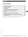
Contents
1. General information 4
2. Design and function 5
3. Safety 6
4. Transport, packaging and storage 11
5. Commissioning, operation 12
6. Faults 17
7. Maintenance, cleaning and recalibration 19
8. Dismounting, return and disposal 20
9. Specifications 21
Contents
Declarations of conformity can be found online at www.wika.com.

4
WIKA operating instructions, models GDM-100-TI, GDM-100-TA
EN
14300398.01 04/2019 EN/DE/FR/ES
1. General information
■
The instrument described in the operating instructions has been designed and
manufactured using state-of-the-art technology. All components are subject to strin-
gent quality and environmental criteria during production. Our management systems
are certified to ISO 9001 and ISO 14001.
■
These operating instructions contain important information on handling the instru-
ment. Working safely requires that all safety instructions and work instructions are
observed.
■
Observe the relevant local accident prevention regulations and general safety regula-
tions for the instrument’s range of use.
■
The operating instructions are part of the product and must be kept in the immediate
vicinity of the instrument and readily accessible to skilled personnel at any time. Pass
the operating instructions on to the next operator or owner of the instrument.
■
Skilled personnel must have carefully read and understood the operating instructions
prior to beginning any work.
■
The general terms and conditions contained in the sales documentation shall apply.
■
Subject to technical modifications.
■
Further information:
- Internet address: www.wika.de / www.wika.com
- Relevant data sheets:
SP 60.05 Model GDM-100-TI
SP 60.06 Model GDM-100-TA
- Application consultant: Tel.: +49 9372 132-0
Fax: +49 9372 132-406
info@wika.de
1. General information

5WIKA operating instructions, models GDM-100-TI, GDM-100-TA
EN
14300398.01 04/2019 EN/DE/FR/ES
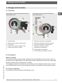
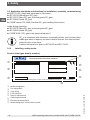
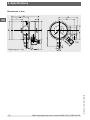
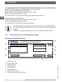
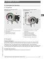
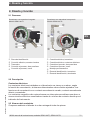
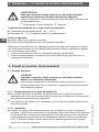
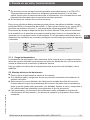
Gas density monitor with integrated transmitter
Model GDM-100-TI
Gas density monitor with built-in transmitter
Model GDM-100-TA
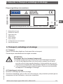
Product label
Electrical connection, cable socket
Transmitter
Process connection, spanner flats
Process connection, thread
Electrical connection, transmitter
Electrical connection, switch contacts
Process connection, spanner flats
Process connection, thread
Extension for transmitter
Product label, transmitter
Product label, gas density monitor
2. Design and function
2.1 Overview
2. Design and function
2.2 Description
Switch contacts
The switch contacts permanently installed in the gas density monitor close or open at
set limit values, depending on the switching function. Switching functions are: Normally
closed, normally open, change-over contact.
The magnetic snap-action contacts are auxiliary current switches which open or close
connected electric circuits via a contact arm which is moved by the instrument pointer.
2.3 Scope of delivery
Cross-check scope of delivery with delivery note.

6
WIKA operating instructions, models GDM-100-TI, GDM-100-TA
EN
14300398.01 04/2019 EN/DE/FR/ES
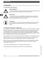
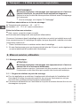
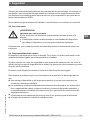
3. Safety
3.1 Explanation of symbols
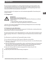
WARNING!
... indicates a potentially dangerous situation that can result in serious
injury or death, if not avoided.
CAUTION!
... indicates a potentially dangerous situation that can result in light injuries
or damage to property or the environment, if not avoided.
Information
... points out useful tips, recommendations and information for efficient
and trouble-free operation.
3.2 Intended use
Wherever the gas density of SF₆ gas has to be indicated locally and, at the same time,
circuits need to be switched, the model GDM-100 gas density monitor finds its use. The
transmitter transmits the measured gas density as an electrical signal.
Gas density monitors are modified contact pressure gauges, specially developed for the
use of SF₆ gas. Temperature influences acting on the enclosed SF₆ gas are compensat-
ed by a compensation system.
The gas density monitors are specially designed for the respective application in switch-
gear (pure SF₆ gas, gas mixtures, calibration pressure, switch points ...). Before use,
check whether this instrument is suitable for the intended application.
Only use the instrument in applications that lie within its technical performance limits
(e.g. max. ambient temperature, material compatibility, ...).
→ For performance limits see chapter 9 “Specifications”.
This instrument is not permitted to be used in hazardous areas!
The instrument has been designed and built solely for the intended use described here,
and may only be used accordingly.
3. Safety

7WIKA operating instructions, models GDM-100-TI, GDM-100-TA
EN
14300398.01 04/2019 EN/DE/FR/ES
The technical specifications contained in these operating instructions must be
observed. Improper handling or operation of the instrument outside of its technical
specifications requires the instrument to be taken out of service immediately and
inspected by an authorised WIKA service engineer.
The manufacturer shall not be liable for claims of any type based on operation contrary
to the intended use.
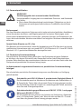
3.3 Improper use
WARNING!
Injuries through improper use
Improper use of the instrument can lead to hazardous situations and
injuries.
▶
Refrain from unauthorised modifications to the instrument.
▶
Do not use the instrument within hazardous areas.
Any use beyond or different to the intended use is considered as improper use.
3.4 Responsibility of the operator
The instrument is used in the industrial sector. The operator is therefore responsible for
legal obligations regarding safety at work.
The safety instructions within these operating instructions, as well as the safety,
accident prevention and environmental protection regulations for the application area
must be maintained.
The operator is obliged to maintain the product label in a legible condition.
To ensure safe working on the instrument, the operating company must ensure
■
that suitable first-aid equipment is available and aid is provided whenever required.
■
that the operating personnel are regularly instructed in all topics regarding work
safety, first aid and environmental protection and know the operating instructions and
in particular, the safety instructions contained therein.
■
that the instrument is suitable for the particular application in accordance with its
intended use.
■
that personal protective equipment is available.
3. Safety

8
WIKA operating instructions, models GDM-100-TI, GDM-100-TA
EN
14300398.01 04/2019 EN/DE/FR/ES
3.5 Personnel qualification
WARNING!
Risk of injury should qualification be insufficient
Improper handling can result in considerable injury and damage to equip-
ment.
▶
The activities described in these operating instructions may only be
carried out by skilled personnel who have the qualifications described
below.
Skilled personnel
Skilled personnel, authorised by the operator, are understood to be personnel who,
based on their technical training, knowledge of measurement and control technology
and on their experience and knowledge of country-specific regulations, current stand-
ards and directives, are capable of carrying out the work described and independently
recognising potential hazards.
Specically when using SF₆ gas
The plant operator must ensure that the handling of SF
6
gas is only carried out by a
qualied company or by qualied persons who have been specially trained in accord-
ance with IEC 61634, section 4.3.1 or IEC 60480, section 10.3.1.
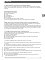
3.6 Personal protective equipment
The personal protective equipment is designed to protect the skilled personnel from
hazards that could impair their safety or health during work. When carrying out the
various tasks on and with the instrument, the skilled personnel must wear personal
protective equipment.
Follow the instructions displayed in the work area regarding personal protective
equipment!
The requisite personal protective equipment must be provided by the operating company.
Safety goggles in accordance with EN 166, class 2, mechanical
strength class S
The safety goggles must be worn over the entire period when working on
hoses or gas containers (e.g. gas cylinders, tanks).
The safety goggles protect the eyes from any flying particles, escaping
gas and liquid splashes.
Protective gloves against heat in accordance with EN ISO 13732-1
and against cold in accordance with EN ISO 13732-3
The protective gloves must be worn over the entire period when working
on hoses, gas containers (e.g. gas cylinders, tanks) or components which
heat up to over 60 °C.
3. Safety

9WIKA operating instructions, models GDM-100-TI, GDM-100-TA
EN
14300398.01 04/2019 EN/DE/FR/ES
3.7 Handling of insulating gases and gas mixtures
SF₆ gas is a greenhouse gas which is listed in the Kyoto Protocol. SF₆ gas must not be
released into the atmosphere, but must be collected in suitable containers.
Properties of insulating gases
■
Colourless and odourless
■
Chemically neutral
■
Inert
■
Not flammable
■
Heavier than air
■
No toxicity
■
No damage to the ozone layer
Detailed information is given in IEC 60376 and IEC 61634.
Danger of suocation caused by insulating gases and gas mixtures
High concentrations of gases can lead to asphyxiation, since breathable air is displaced
from the lungs with the inhalation of gas.
Since SF₆ gas is heavier than air, it collects, especially, at ground level or lower-lying
rooms below the reference level (e.g. cellars). This is particularly dangerous since SF₆
gas is colourless and odourless and thus may be imperceptible to people.
3.8 Danger caused by decomposition products
Insulating gas in electrical systems may contain decomposition products generated by
electric arcs:
■
Gaseous sulphur fluorides
■
Sulphur hexafluorides
■
Solid and atomized metal fluorides, metal sulfides, metal oxides
■
Hydrogen fluoride
■
Sulphur dioxide
Decomposition products can be harmful to health.
■
They can cause poisoning by inhalation, ingestion or contact with the skin.
■
They may be irritating to the eyes, the respiratory system or the skin and burn them.
■
Inhalation of large quantities may damage the lungs.
Observe the following safety instructions in order to avoid danger from insulating gas:
■
Wear personal protective equipment.
■
Read the material safety data sheet of the gas supplier.
■
With large leaks, evacuate the area quickly.
■
Ensure good ventilation.
■
Ensure the leak tightness of the equipment with a leak detector (e.g. model GIR-10).
3. Safety

10
WIKA operating instructions, models GDM-100-TI, GDM-100-TA
EN
14300398.01 04/2019 EN/DE/FR/ES
3. Safety
3.9 Applicable standards and directives for installation, assembly, commissioning
■
BGI 753 (SF₆ plants and equipment in Germany)
■
IEC 61634 (Handling of SF₆ gas)
■
IEC 60376 (New SF₆ gas, technical grade SF₆ gas)
■
IEC 60480 (Used SF₆ gas)
■
CIGRE report 276, 2005 (Practical SF₆ gas handling instructions)
Leaks during operation:
■
IEC 60376 (New SF₆ gas, technical grade SF₆ gas)
■
IEC 60480 (Used SF₆ gas)
■
CIGRE 2002 (“SF₆ gas in the electrical industry”)
SF
6
is a colourless and odourless, chemically neutral, inert and non-am-
mable gas which is approx. ve times heavier than air, non-toxic and not
harmful to the ozone layer.
Detailed information is given in IEC 60376 and IEC 61634.
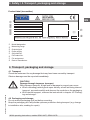
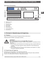
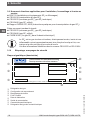
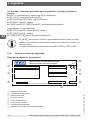
3.10 Labelling, safety marks
Product label (gas density monitor)
Model designation
Pin assignment
Case filling
P# Product No.
Date of manufacture
Switching thresholds
Electrical characteristics
Model designation of the switch contact
Dichtewächter mit Kontakteinrichtung
Density monitor with alarm contacts
Schaltzustand bei Skalenanfangswert / Status of switch at minimum scale value Made in Germany

11WIKA operating instructions, models GDM-100-TI, GDM-100-TA
EN
14300398.01 04/2019 EN/DE/FR/ES
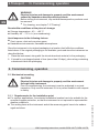
3. Safety / 4. Transport, packaging and storage
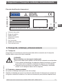
Product label (transmitter)
Model designation
Measuring range
Output signal
Power supply
S# Article No.
P# Product No.
Pin assignment
Date of manufacture
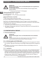
4. Transport, packaging and storage
4.1 Transport
Check the instrument for any damage that may have been caused by transport.
Obvious damage must be reported immediately.
CAUTION!
Damage through improper transport
With improper transport, a high level of damage to property can occur.
▶
When unloading packed goods upon delivery as well as during internal
transport, proceed carefully and observe the symbols on the packaging.
▶
With internal transport, observe the instructions in chapter 4.2 “Packag-
ing and storage”.
4.2 Packaging and storage
Do not remove packaging until just before mounting.
Keep the packaging as it will provide optimum protection during transport (e.g. change
in installation site, sending for repair).

12
WIKA operating instructions, models GDM-100-TI, GDM-100-TA
EN
14300398.01 04/2019 EN/DE/FR/ES
WARNING!
Physical injuries and damage to property and the environment
caused by hazardous decomposition products
Before storing the instrument, any residual decomposition products must
be removed.
▶
For cleaning, see chapter 7.2 “Cleaning”
Permissible conditions at the place of storage:
■
Storage temperature: -40 ... +60 °C
■
Humidity: 45 ... 75 % r.h. (non-condensing)
Avoid exposure to the following factors:
■
Soot, vapour, dust and corrosive gases
■
Hazardous environments, flammable atmospheres
Store the instrument in its original packaging in a location that fulfils the conditions
listed above. If the original packaging is not available, pack and store the instrument as
described below:
1. Place the instrument, along with the shock-absorbent material, in the packaging.
2. If stored for a prolonged period of time (more than 30 days), place a bag containing
a desiccant inside the packaging.
5. Commissioning, operation
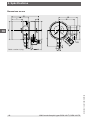
5.1 Mechanical mounting
CAUTION!
Physical injuries and damage to property and the environment
through faulty instrument
Prior to commissioning, the instrument must be subjected to a visual
inspection. Only use the instrument if it is in perfect condition with respect
to safety.
5.1.1 Requirements for the installation point
■
For outdoor applications, the selected installation location has to be suitable for the
specified ingress protection, so that the instrument is not exposed to impermissible
weather conditions.
■
The sealing faces at the instrument and at the measuring point have to be undam-
aged and clean.
4.Transport, ... / 5. Commissioning, operation

13WIKA operating instructions, models GDM-100-TI, GDM-100-TA
EN
14300398.01 04/2019 EN/DE/FR/ES
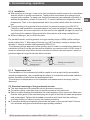
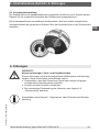
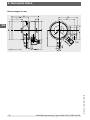
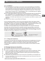
5.1.2 Installation
■
With transport or storage, it can occur that gas density monitors warm up or cool down
and this results in pointer movements. These pointer movements are caused by the
compensation system. To make sure that the instruments have adapted sufficiently to
ambient temperature, at least 2 hours at 20 °C must be allowed for adaptation to the
temperature. Then, in the depressurised state, the pointer will sit within the tolerance
bar.
■
Corresponding to the general technical rules for pressure gauges (e.g. EN 837-2
“Selection and installation recommendations for pressure gauges”) when screwing in
the instrument, the force required to do this must not be applied through the case, but
only through the spanner flats provided for this purpose and using a suitable tool.
■
When screwing in, do not tilt the threads.
For parallel threads, use flat gaskets, lens-type sealing rings or WIKA profile sealings
at the sealing face . With tapered threads (e.g. NPT threads), sealing is made in the
threads , using a suitable sealing material (EN 837-2).
The tightening torque depends on the sealing used. In order to orientate the measuring
instrument so that it can be read as well as possible, a connection with LH-RH union or
union nut should be used. When a blow-out device is fitted to an instrument, it must be
protected against being blocked by debris and dirt.
5.1.3 Temperature load
The installation of the instrument should be made in such a way that the permissible
operating temperature, also considering the effects of convection and thermal radiation,
neither exceeds nor falls below the permissible limits.
The influence of temperature on the indication and measurement accuracy must be
observed.
5.2 Electrical mounting of the gas density monitor
■
The instrument must be grounded via the process connection.
■
For cable outlets, make sure that no moisture enters at the cable end.
■
Select a cable diameter that matches the cable bushing of the connector. Make sure
that the cable gland of the mounted plug has a tight fit and that the seals are present
and undamaged. Tighten the threaded connection and check that the sealing is
correctly seated, in order to ensure the ingress protection.
■
Connection details and switching functions are given on the product label. Connec-
tion terminals and ground terminal are appropriately marked.
Sealing in the thread
Spanner ats
Sealing face
5. Commissioning, operation

14
WIKA operating instructions, models GDM-100-TI, GDM-100-TA
EN
14300398.01 04/2019 EN/DE/FR/ES
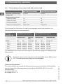
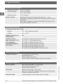
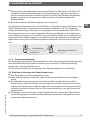
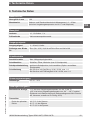
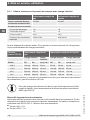
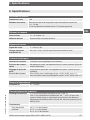
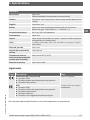
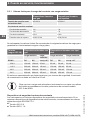
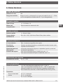
5.2.1 Limit values for the contact load with resistive load
gas-filled instruments liquid-filled instruments
Maximum rated operating
voltage Ueff
AC 250 V AC 250 V
Rated operating current
Switch-on current 1 A 1 A
Switch-off current 1 A 1 A
Continuous current 0.6 A 0.6 A
Maximum switching power 30 W, 50 VA 20 W, 20 VA
Do not exceed the limit values. In order to permanently ensure safe operation, the
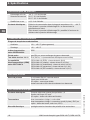
following load values are recommended:
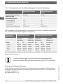
Voltage
(per IEC 38)
gas-filled instruments liquid-filled instruments
resistive load inductive
load
resistive load inductive load
DC/AC DC AC cos ϕ >0.7 DC AC cos ϕ >0.7
230 V 100 mA 120 mA 65 mA 65 mA 90 mA 40 mA
110 V 200 mA 240 mA 130 mA 130 mA 180 mA 85 mA
48 V 300 mA 450 mA 200 mA 190 mA 330 mA 130 mA
24 V 400 mA 600 mA 250 mA 250 mA 450 mA 150 mA
The switching current must not be less than 20 mA with low voltages for switching relia-
bility reasons.
For higher loads, and for instruments with liquid-lled cases, WIKA model
905.1X contact protection relays are recommended
Overcurrent protectors
The instruments do not provide for incorporated overcurrent protectors. Should protec-
tors be required, the following values in accordance with EN 60 947-5-1 are to be
recommended.
■
Voltage 24 V: 2 A
■
Voltage 250 V: 1 A
5. Commissioning, operation

15WIKA operating instructions, models GDM-100-TI, GDM-100-TA
EN
14300398.01 04/2019 EN/DE/FR/ES
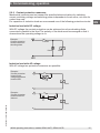
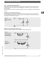
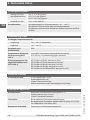
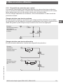
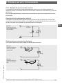
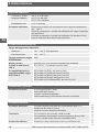
5.2.2 Contact protection measures
Mechanical contacts must not exceed the specified electrical values for switching
current, switching voltage and switching power independent of each other, not even for
a short time only.
For capacitive or inductive loads we recommend one of the following protective circuits:
Inductive load with DC voltage
With DC voltage the contact protection can be achieved via a free-wheeling diode,
connected in parallel to the load. The polarity of the diode must be arranged so that it
closes when the operating voltage is on.
Inductive load with AC voltage
With AC voltage two protection measures are possible:
Example:
Contact protection
measure with free-
wheeling diode
Contact
Diode
Load
Example:
Contact protection
measure with
voltage-dependent
resistor VDR
Example:
Contact protection
measure with RC
element
Load
Load
5. Commissioning, operation

16
WIKA operating instructions, models GDM-100-TI, GDM-100-TA
EN
14300398.01 04/2019 EN/DE/FR/ES
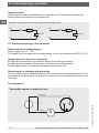
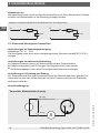
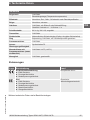
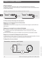
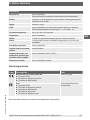
Capacitive load
With capacitive loads elevated switch-on currents arise. These can be reduced by
series-connecting resistors in the supply line.
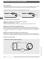
5.3 Electrical mounting of the transmitter
Requirements for voltage supply
Power supply: DC 10 ... 30 V
The supply must be made via an energy-limited circuit in accordance with IEC 61010-1.
Requirements for electrical connection
■
Cable diameter matches the cable bushing of the mating connector.
■
Cable gland and seals of the mating connector are correctly seated.
■
With cable outlets, no humidity can ingress at the cable end.
Requirement for shielding and grounding
The transmitter is grounded via the process connection of the gas density monitor. The
transmitter is connected with the process connection of the gas density monitor via the
mounting.
Pin assignment
Examples: Contact protection measure with current-limiting resistor
Load Load
U
B
R
1
U
B
R
1
Transmitter, angular connector (2-pin)
+
-
U
A
UB+/Sig+
0V/Sig-
5. Commissioning, operation

17WIKA operating instructions, models GDM-100-TI, GDM-100-TA
EN
14300398.01 04/2019 EN/DE/FR/ES
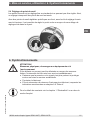
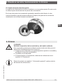
5.4 Switch point setting
The switch points have a fixed setting as standard and cannot be adjusted. Thus, an
undesired adjustment of the switch points is excluded.
With customer-specific, adjustable switch points, with the accompanying adjustment
key, the desired set point can be set via the adjustment lock in the window.
6. Faults
CAUTION!
Physical injuries and damage to property and the environment
If faults cannot be eliminated by means of the listed measures, the instru-
ment must be taken out of operation immediately.
▶
Ensure that pressure or signal is no longer present and protect against
accidental commissioning.
▶
Contact the manufacturer.
▶
If a return is needed, please follow the instructions given in chapter 9.2
“Return”.
For contact details see chapter 1 “General information” or the back page
of the operating instructions.
5. Commissioning, operation / 6. Faults

18
WIKA operating instructions, models GDM-100-TI, GDM-100-TA
EN
14300398.01 04/2019 EN/DE/FR/ES
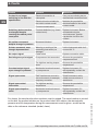
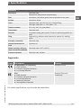
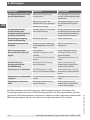
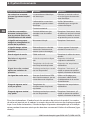
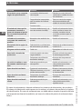
Faults Causes Measures
Contact is no longer
switching in line with the
specification
Electrical connection is
interrupted.
Carry out a continuity test on
the electrical connection lines.
Electrical load unsuitable for
the switch contact model.
Maintain the permissible
electrical loads for the switch
contact model.
Contact contaminated.
Switching status remains
unchanged despite
reaching the switch point/
reset point
Contacts defective (e.g. fused
contact zone).
Replace instrument. Before
recommissioning the
new instrument, provide
a protective circuit for the
contact.
No pointer movement
despite change in pressure
Movement blocked. Replace instrument.
Pointer movement, even
though depressurised
Warming or cooling of the
measuring instrument (no
damage)
Let the instrument settle for 2
hours at 20 °C.
No output signal Cable break Replace connection cable
Deviating zero point signal Overpressure limit exceeded Observe the permissible
overpressure limit
Too high/low working temper-
ature
Observe the permissible
temperatures
Constant output signal
upon change in pressure
Mechanical overload caused
by overpressure
Replace instrument; if it
fails repeatedly, contact the
manufacturer
Signal span varies EMC interference sources in
the environment; for example,
frequency converter
Shield instrument; cable
shield; remove source of
interference
Signal span varies/
inaccurate
Too high/low working
temperature
Observe the permissible
temperatures
Signal span drops/too
small
Mechanical overload caused
by overpressure
Replace instrument; if it
fails repeatedly, contact the
manufacturer
For claims, the serial and product numbers must be stated. The serial number is printed
on the dial, the product number on the product label. With claims, the atmospheric
pressure and the temperature during the measurement must be given, as well as the
data on the reference standard (model, class).
6. Faults

19WIKA operating instructions, models GDM-100-TI, GDM-100-TA
EN
14300398.01 04/2019 EN/DE/FR/ES
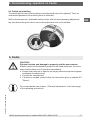
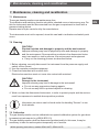
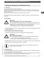
7. Maintenance, cleaning and recalibration
7.1 Maintenance
These gas density monitors are maintenance-free.
The indication and switching function should be checked once or twice every year. For
this the instrument must be disconnected from the gas compartment to check with a
pressure testing device.
Repairs must only be carried out by the manufacturer.
The instruments must not be opened, since this can lead to indication and switch point
errors.
7.2 Cleaning
CAUTION!
Physical injuries and damage to property and the environment
Improper cleaning may lead to physical injuries and damage to property
and the environment. Decomposition products in the dismounted instru-
ment can result in a risk to persons, the environment and equipment.
▶
Carry out the cleaning process as described below.
1. Before cleaning, correctly disconnect the instrument from the pressure supply and
switch o the current.
2. Use the requisite protective equipment.
3. Clean the instrument with a moist cloth.
Electrical connections must not come into contact with moisture!
CAUTION!
Damage to the instrument
Improper cleaning may lead to damage to the instrument!
▶
Do not use any aggressive cleaning agents.
▶
Do not use any hard or pointed objects for cleaning.
4. Wash or clean the dismounted instrument, in order to protect people and the environ-
ment from exposure to residual decomposition products.
Information on returns can be found under the heading “Service” on our
local website.
7.3 Calibration
The gas density monitor can be calibrated via a special calibration system for gas densi-
ty measuring instruments (e.g. WIKA BCS-10).
The gas density monitor must be dismounted professionally. In this case, it may be
necessary to take the entire system temporarily out of service.
7. Maintenance, cleaning and recalibration

20
WIKA operating instructions, models GDM-100-TI, GDM-100-TA
EN
14300398.01 04/2019 EN/DE/FR/ES
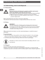
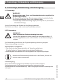
8. Dismounting, return and disposal
8.1 Dismounting
WARNING!
Physical injuries and damage to property and the environment
caused by hazardous decomposition products
Upon contact with hazardous decomposition products, there is a danger
of physical injuries and damage to property and the environment.
▶
Wear the requisite protective equipment (see chapter 3.6 “Personal
protective equipment”).
Before dismantling the instrument, evacuate the gas filling.
Only dismount the instrument when it is depressurised and free from current.
8.2 Return
WARNING!
Strictly observe the following when shipping the instrument:
All instruments delivered to WIKA must be free from any kind of hazard-
ous substances (e.g. decomposition products) and must therefore be
cleaned before being returned.
When returning the instrument, use the original packaging or a suitable transport
packaging.
To avoid damage:
1. Place the instrument, along with the shock-absorbent material, in the packaging.
Place shock-absorbent material evenly on all sides of the transport packaging.
2. If possible, place a bag containing a desiccant inside the packaging.
Information on returns can be found under the heading “Service” on our
local website.
8.3 Disposal
Incorrect disposal can put the environment at risk.
Dispose of instrument components and packaging materials in an environmentally
compatible way and in accordance with the country-specific waste disposal regulations.
8. Dismounting, return and disposal
La page est en cours de chargement...
La page est en cours de chargement...
La page est en cours de chargement...
La page est en cours de chargement...
La page est en cours de chargement...
La page est en cours de chargement...
La page est en cours de chargement...
La page est en cours de chargement...
La page est en cours de chargement...
La page est en cours de chargement...
La page est en cours de chargement...
La page est en cours de chargement...
La page est en cours de chargement...
La page est en cours de chargement...
La page est en cours de chargement...
La page est en cours de chargement...
La page est en cours de chargement...
La page est en cours de chargement...
La page est en cours de chargement...
La page est en cours de chargement...
La page est en cours de chargement...
La page est en cours de chargement...
La page est en cours de chargement...
La page est en cours de chargement...
La page est en cours de chargement...
La page est en cours de chargement...
La page est en cours de chargement...
La page est en cours de chargement...
La page est en cours de chargement...
La page est en cours de chargement...
La page est en cours de chargement...
La page est en cours de chargement...
La page est en cours de chargement...
La page est en cours de chargement...
La page est en cours de chargement...
La page est en cours de chargement...
La page est en cours de chargement...
La page est en cours de chargement...
La page est en cours de chargement...
La page est en cours de chargement...
La page est en cours de chargement...
La page est en cours de chargement...
La page est en cours de chargement...
La page est en cours de chargement...
La page est en cours de chargement...
La page est en cours de chargement...
La page est en cours de chargement...
La page est en cours de chargement...
La page est en cours de chargement...
La page est en cours de chargement...
La page est en cours de chargement...
La page est en cours de chargement...
La page est en cours de chargement...
La page est en cours de chargement...
La page est en cours de chargement...
La page est en cours de chargement...
La page est en cours de chargement...
La page est en cours de chargement...
La page est en cours de chargement...
La page est en cours de chargement...
La page est en cours de chargement...
La page est en cours de chargement...
La page est en cours de chargement...
La page est en cours de chargement...
La page est en cours de chargement...
La page est en cours de chargement...
La page est en cours de chargement...
La page est en cours de chargement...
La page est en cours de chargement...
La page est en cours de chargement...
La page est en cours de chargement...
La page est en cours de chargement...
-
 1
1
-
 2
2
-
 3
3
-
 4
4
-
 5
5
-
 6
6
-
 7
7
-
 8
8
-
 9
9
-
 10
10
-
 11
11
-
 12
12
-
 13
13
-
 14
14
-
 15
15
-
 16
16
-
 17
17
-
 18
18
-
 19
19
-
 20
20
-
 21
21
-
 22
22
-
 23
23
-
 24
24
-
 25
25
-
 26
26
-
 27
27
-
 28
28
-
 29
29
-
 30
30
-
 31
31
-
 32
32
-
 33
33
-
 34
34
-
 35
35
-
 36
36
-
 37
37
-
 38
38
-
 39
39
-
 40
40
-
 41
41
-
 42
42
-
 43
43
-
 44
44
-
 45
45
-
 46
46
-
 47
47
-
 48
48
-
 49
49
-
 50
50
-
 51
51
-
 52
52
-
 53
53
-
 54
54
-
 55
55
-
 56
56
-
 57
57
-
 58
58
-
 59
59
-
 60
60
-
 61
61
-
 62
62
-
 63
63
-
 64
64
-
 65
65
-
 66
66
-
 67
67
-
 68
68
-
 69
69
-
 70
70
-
 71
71
-
 72
72
-
 73
73
-
 74
74
-
 75
75
-
 76
76
-
 77
77
-
 78
78
-
 79
79
-
 80
80
-
 81
81
-
 82
82
-
 83
83
-
 84
84
-
 85
85
-
 86
86
-
 87
87
-
 88
88
-
 89
89
-
 90
90
-
 91
91
-
 92
92


WIKA GDM-100-TA tag:model:GDM-100-TI Manuel utilisateur
- Taper
- Manuel utilisateur
- Ce manuel convient également à
dans d''autres langues
Documents connexes
-
WIKA GDM-RC-100 Mode d'emploi
-
-
-
 mensor Mensor CPC2000 Mode d'emploi
-
-
-
-
WIKA PSD-4-ECO Mode d'emploi
-
-
