Han Networks AP311H Guide d'installation
- Taper
- Guide d'installation

HAN NETWORKS
AP311H
Installation Guide
XXXXXX-XX Rev. A
*XXXXXX-XX Rev. A*
Introduction
The Multi-functional AP311H access point is a highly
versatile, and performance rich access point providing
operational simplicity and a quality user experience. This
indoor WiFi access point provides high-performance
Gigabit WiFi for in-room applications such as hotels,
classrooms, dormitories, clinics, remote/home office and
more.
The AP311H offers Gigabit ethernet uplink, 3x Gigabit
downlink one of which supports 802.3af PSE to power the
attached device, one pair of RJ-45 pass through ports, and
a USB 2.0 port.
The AP311H ships with a mounting plate to attach the AP
to a single-gang wall-box (most international variations
covered). A desk mount kit can be ordered separately.
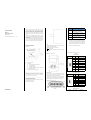
Package Contents
Figure 1
A. AP311H Access Point
B. Documents:
1) Installation Guide (this document)
2) Quick Start Guide
3) User Guide Info Card
4) Regulatory Compliance and Safety Information
C. (2x) #6-32 slotted screws
D. Single-gang wall-box mounting plate
____________________________________________________
_
Inform your supplier if there are any incorrect, missing, or
damaged parts. If possible, retain the carton, including the
original packing materials. Use these materials to repack and
return the unit to the supplier if needed.
____________________________________________________
_
Hardware Overview
The following sections outline the hardware components
of the AP311H access point.
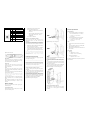
Figure 2 AP311H Front View
LED
The LED displays located on the front of the access point
indicate the following functions:
STATUS:
System status (Tr i -color LED)
PSE:
PoE-PSE status
For the details of the LED status, please refer to the Quick
Start Guide.
Figure 3 AP311H Rear View
Ethernet Ports
The AP311H access point is equipped with four active
Ethernet ports. One is shown in Figure 3 (Eth0) and the
others are shown in Figure 4 (Eth1-Eth3/PSE).
In addition, the AP311H AP has one pair of RJ-45 passive
pass through ports, which provide an electrical connection
between the back and the bottom of the access point.
Figure 4 AP311H Bottom View
Tab le 1
Interface
Description
Eth0
1 × 10/100/1000Base-T auto-sensing
uplink connectivity (RJ-45) port. IEEE
802.3af/802.3at PoE compliant.
Eth1~
~Eth2
2 x 10/100/1000Base-T auto-sensing
downlink connectivity (RJ-45) ports.
☆Eth3/PSE
1 × 10/100/1000Base-T auto-sensing
downlink connectivity (RJ-45) port. IEEE
802.3af PoE-PSE compliant.
PT
One pair passive Pass-Through ports
(two RJ-45, back and bottom)
☆ Note: When the AP311H is powered by an 802.3at or
DC power source, the PoE-out (PoE-PSE) functionality
is enabled on port Eth3/PSE, supplying (1) maximum
output of 12W while USB is active, or (2) maximum
output of 14.5W while USB is inactive.
Figure 5 Gigabit Ethernet Port Pin-Out
Tab le 2
Eth0 Port Pinout
Connector!
Pin!
Signal
Name!
Function!
1
BI_DA+
Bi-directional pair +A,
PoE Negative
2
BI_DA-
Bi-directional pair -A,
PoE Negative
3
BI_DB+
Bi-directional pair +B,
PoE Positive
4
BI_DC+
Bi-directional pair +C,
PoE Positive
5
BI_DC-
Bi-directional pair -C,
PoE Positive
6
BI_DB-
Bi-directional pair -B,
PoE Positive
7
BI_DD+
Bi-directional pair +D,
PoE Negative
8
BI_DD-
Bi-directional pair -D,
PoE Negative
Tab le 3
Eth1~Eth2 Port Pinout
Connector!
Pin!
Signal
Name!
Function!
1
BI_DA+
Bi-directional pair +A
2
BI_DA-
Bi-directional pair -A
3
BI_DB+
Bi-directional pair +B
4
BI_DC+
Bi-directional pair +C
5
BI_DC-
Bi-directional pair -C
6
BI_DB-
Bi-directional pair -B
7
BI_DD+
Bi-directional pair +D
8
BI_DD-
Bi-directional pair -D
Tab le 4
Eth3/PSE Port Pinout
Connector!
Pin!
Signal
Function!

Name!
1
BI_DA+
Bi-directional pair +A
2
BI_DA-
Bi-directional pair -A
3
BI_DB+
Bi-directional pair +B
4
BI_DC+
Bi-directional pair +C,
PoE Positive
5
BI_DC-
Bi-directional pair -C,
PoE Positive
6
BI_DB-
Bi-directional pair -B
7
BI_DD+
Bi-directional pair +D,
PoE Negative
8
BI_DD-
Bi-directional pair -D,
PoE Negative
Figure 6 AP311H Side View
USB Interface
The AP311H access point is equipped with a USB 2.0
interface (Type A). When active, the USB port can supply
up to 5V/0.5A power to an attached device.
Reset button
Factory reset. Press reset button for 5s, AP LEDs will
quickly flash for 3s, then AP will restart and restore
factory configurations.
Power
The AP311H access point supports direct DC power
adapter (48V DC nominal, sold separately) and Power over
Ethernet (PoE).
The DC power connector port is located on the side of the
device, as shown in Figure 6.
When both power sources are available, DC power takes
priority over PoE. AP supports the power adapter
provided by HAN ONLY.
The PoE-in allows the Eth0 port to draw power from an
802.3at (preferred) source, or an 802.3af (optional)
source.
When powered by an 802.3at or DC power source, the
PoE-out (PoE-PSE) functionality is enabled on port
Eth3/PSE.
Before You Begin
Refer to the sections below before beginning the
installation process.
Pre-Installation Checklist
Before installing your AP311H access point, be sure that
you have the following items:
• Gigabit Ethernet cable of required length.
• One of the following power sources:
§ IEEE 802.3af/at compliant Power over Ethernet
(PoE) source.
§ HAN AC-DC adapter (sold separately),Output
voltage DC 48V, output current ≥ 0.6A is
recommended.
• A PC terminal or a notebook
Identifying Specific Installation Locations
The AP311H access point must be secured to an
HAN-approved wall or to a desk mount kit (sold
separately).
The installation position should be as close as possible to
the center of the required coverage area and should be
free from obstructions or obvious sources of interference.
• Minimize the number of obstructions (such as walls)
between the AP and user terminals.
• Electronic equipment or devices (such as microwave
ovens) which may produce radio frequency noise
should be away from the installation position of the
AP.
It is strictly prohibited to install around stagnant water,
water seepage, leakage or condensation. Avoid cable
condensation or water seepage along the cables
connecting to the AP.
Installing the Access Point
The AP311H can be mounted into a single-gang wall-box
with shipped mounting plate.
____________________________________________________
_
Installing all HAN access points requires professional training. The
AP must be professionally installed by a qualified engineer familiar
with WLAN system. Failure to properly install this product may
result in physical injury and/or damage to property.
____________________________________________________
_
Use the steps below to install your AP311H.
1. Begin by removing the existing data wall plate (if
applicable).
2. Make sure that there is an uplink Ethernet cable with
RJ-45 plug in the wall-box. If not, please crimp an RJ-45
plug (not supplied) on the Ethernet cable.
3. Align the mounting holes of the AP311H mounting plate
with mounting holes in your gang box, as shown in Figure 7
and Figure 8. For worldwide single gang outlet box, the
mounting plate has two sets of mounting holes to meet
the individual installation position requirement.
Figure 7 Mounting Plate to Gang Box(1)
Figure 8 Mounting Plate to Gang Box (2)
4. Insert the two included slotted screws and tighten them
to secure the mounting plate.
5. Connect the uplink Ethernet cable to the Eth0 port on
the back of the AP311H. Do the same for the PT port, if
used.
6. Align the mounting slots on the back of the AP311H with
the corresponding mounting posts on the wall mounting
plate as shown in Figure 9.
7. Push the access point against the posts and downward
until the posts engage the slots at the top of the slots.
Figure 9 Attaching AP311H to wall mounting plate
Verifying Post-Installation Connectivity
The integrated LED on the access point can be used to
verify that the AP is receiving power and initializing
successfully.
Product Specifications
Dimensions/Weight
• Single AP excluding packing box and accessories:
§ 95 mm (W) x 34.45 mm (D) x 161.5 mm (H)
§ 3.74” (W) x 1.35” (D) x 6.35” (H)
§ 237g/0.522lb
• Single AP including packing box and accessories:
§ 115 mm (W) x 54 mm (D) x 182 mm (H)
§ 4.52” (W) x 2.13” (D) x 7.17”(H)
§ 417g/0.919lb
Power
• Supports direct DC power and Power over Ethernet
(PoE)
• Power over Ethernet (PoE): 48 V DC (nominal) IEEE
802.3af/ 802.3at compliant source
• Maximum power consumption with PSE function and
USB load: 25W
Environmental
• Operating :
§ Temperature: 0°C to +50°C
§ Humidity: 5% to 95% non-condensing
• Storage and transportation :
§ Temperature: -40°C to +70°C
For additional specifications on this product, please refer
to the Datasheet.

HAN NETWORKS
AP311H Regulatory Compliance and
Safety Information
xxxxxx-xx Rev. x
*xxxxxx-xx Rev. x*
n Introduction
This document contains domestic and international regulatory
compliance information for the access point AP311H. To ensure
that this device complies with the regulatory standards for your
region, please refer to the content below.
FCC Part 15:
This equipment has been tested and found to comply with the
limits for a Class B digital device, pursuant to Part15 of the FCC
Rules.
These limits are designed to provide reasonable protection
against harmful interference in a residential installation. This
equipment generate, uses and can radiate radio frequency
energy and, if not installed and used in accordance with the
instructions, may cause harmful interference to radio
communications.
However, there is no guarantee that interference will not occur
in a particular installation. If this equipment does cause harmful
interference to radio or television reception, which can be
determined by turning the equipment off and on, the user is
encouraged to try to correct the interference by one of the
following measures:
l Reorient or relocate the receiving antenna.
l Increase the separation between the equipment and
receiver.
l Connect the equipment into an outlet on a circuit
different from that to which the receiver is connected.
l Consult the dealer or an experienced radio/TV technician
for help.
This device complies with Part 15 of the FCC Rules. Operation is
subject to the following two conditions:
(1) This device may not cause harmful interference, and (2) this
device must accept any interference received, including
interference that may cause undesired operation.
FCC Caution: Any changes or modifications not expressly
approved by the party responsible for compliance could void the
user's authority to operate this equipment.
RF exposure warning
This equipment complies with FCC radiation exposure limits set
forth for an uncontrolled environment.
This product may not be collocated or operated in conjunction
with any other antenna or transmitter
This equipment must be installed and operated in accordance
with provided instructions and the antenna(s) used for this
transmitter must be installed to provide a separation distance of
at least 20 cm from all persons and must not be collocated or
operating in conjunction with any other antenna or transmitter.
For EU
HAN NETWORKS CO., hereby declares that these models are
compliant with the essential requirements and other provisions
of Directive 2014/53/EU. For the complete CE DoC, please access
the website below to get more information:
https://businessportal2.alcatel-lucent.com/
Waste Electrical and Electronic Equipment (WEEE) Statement
HAN products are subject to separate
collection and treatment in the EU Member
States, Norway, and Switzerland when they
are at end of life, and therefore are marked
with the symbol shown. The treatment
applied to these products in these countries
shall be compliant with the applicable
national laws which are under the
implementing of Directive 2012/19/EU on Waste of Electrical and
Electronic Equipment (WEEE).
European Union RoHS
HAN products are compliant with the EU Restriction of Hazardous
Substances Directive 2011/65/EU (RoHS). EU RoHS restricts the
use of specific hazardous materials in the manufacture of
electrical and electronic equipment. The restricted materials
under the Directive are Lead (including Solder used in printed
circuit assemblies), Cadmium, Mercury, equivalent Chromium,
and Bromine.
n Global RF health information:
RF Radiation Exposure Statement: This equipment complies
with FCC and CE RF radiation exposure limits. This equipment
should be installed and operated with a minimum distance of
20 cm between the equipment and a human’s body for 2.4 GHz
and 5 GHz operations. This transmitter must not be co-located
or operating in conjunction with any other antenna or
transmitter.
The device is restricted to indoor use only when operating in the
5150 to 5350 MHz frequency range.
successful communication.
Conformément à la réglementation d'Industrie Canada, le présent
émetteur radio peut
fonctionner avec une antenne d'un type et d'un gain maximal (ou
inférieur) approuvé pour l'émetteur par Industrie Canada. Dans le
but de réduire les risques de brouillage radioélectrique à
l'intention des autres utilisateurs, il faut choisir le type d'antenne
et son gain de sorte que la puissance isotrope rayonnée
équivalente (p.i.r.e.) ne dépasse pas l'intensité nécessaire à
l'établissement d'une communication satisfaisante.
User manuals for transmitters equipped with detachable
antennas shall also contain the following notice in a conspicuous
location:
This radio transmitter (identify the device by certification
number, or model number if
Category II) has been approved by Industry Canada to operate
with the antenna types listed below with the maximum
permissible gain and required antenna impedance for each
antenna type indicated. Antenna types not included in this list,
having a gain greater than the maximum gain indicated for that
type, are strictly prohibited for use with this device.
Le présent émetteur radio (identifier le dispositif par son numéro
de certification ou son numéro de modèle s'il fait partie du
matériel de catégorie I) a été approuvé par Industrie Canada
pour fonctionner avec les types d'antenne énumérés ci-dessous et
ayant un gain admissible maximal et l'impédance requise pour
chaque type d'antenne. Les types d'antenne non inclus dans cette
liste,ou dont le gain est supérieur au gain maximal indiqué, sont
strictement interdits pour l'exploitation de l'émetteur.
IMPORTANT NOTE:
Radiation Exposure Statement:
This equipment complies with “Industry Canada RSS-102 for
radiation exposure limits set forth for an uncontrolled
environment”.
This equipment should be installed and operated with minimum
distance 20cm between the radiator and your body.
Déclarationd'exposition aux radiations:
Cetéquipementestconforme aux limitesd'exposition aux
rayonnements IC établies pour un environnement non contrôlé.
Cetéquipementdoitêtreinstallé et utilisé avec un minimum de
20cm de distance entre la source de rayonnement et votre corps.
Industry Canada – Emissions compliance statement
This Class B digital apparatus complies with Canadian ICES-003.
Avis de Conformité à la Réglementationd’ Industrie Canada.
Cetappareilnumérique de la classe B est conform à la norme NMB-
003 du Canada.
[REMAINING SECTIONS INTENTIONALLY LEFT BLANK]
-
 1
1
-
 2
2
-
 3
3


Han Networks AP311H Guide d'installation
- Taper
- Guide d'installation
dans d''autres langues
Autres documents
-
Dell W-AP124/125 Mode d'emploi
-
Dell W-Series 324/325 Access Points Le manuel du propriétaire
-
Dell W-Series 314/315 Access Points Le manuel du propriétaire
-
Dell W-Series 334/335 Access Points Le manuel du propriétaire
-
-
Aruba Networks AP-214 Guide d'installation
-
Alcatel-Lucent OAW-AP228 Guide d'installation
-
-
Dell W-Series 228 Access Points Le manuel du propriétaire