Cameo OTOS® H5 Manuel utilisateur
- Catégorie
- Projecteurs
- Taper
- Manuel utilisateur

USER‘S MANUAL
BEDIENUNGSANLEITUNG
MANUEL D‘UTILISATION
MANUAL DE USUARIO
INSTRUKCJA OBSŁUGI
MANUALE D‘USO
OTOS® H5
BEAM SPOT WASH HYBRID MOVING HEAD IP65
CLOTOSH5
ANIMATION WHEEL

CONTENTS / INHALTSVERZEICHNIS / CONTENU / CONTENIDO / TREŚĆ /
CONTENUTO
ENGLISH
INFORMATION ON THIS USER MANUAL 6
INTENDED USE 6
DEFINITIONS AND SYMBOL EXPLANATIONS 6
SAFETY INSTRUCTIONS 7
NOTES ON PORTABLE OUTDOOR DEVICES 11
INCLUDED 11
INTRODUCTION 12
CONNECTIONS, OPERATING AND DISPLAY ELEMENTS 12
OPERATION 15
W-DMX™ STATUS 17
SETUP AND INSTALLATION 25
CARE, MAINTENANCE AND REPAIR 26
REPLACING THE LAMP 27
CALIBRATING THE LAMP 29
REPLACING GOBOS 31
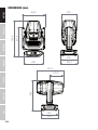
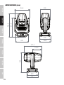
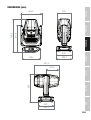
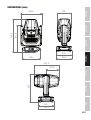
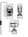
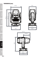
DIMENSIONS (mm) 34
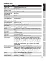
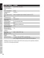
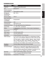
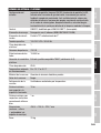
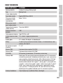
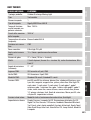
TECHNICAL DATA 35
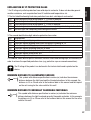
EXPLANATION OF IP PROTECTION CLASS 37
MINIMUM DISTANCE TO ILLUMINATED SURFACE 37
MINIMUM DISTANCE TO NORMALLY FLAMMABLE MATERIALS 37
DISPOSAL 38
MANUFACTURER’S DECLARATIONS 38
DEUTSCH
INFORMATIONEN ZU DIESER BEDIENUNGSANLEITUNG 40
BESTIMMUNGSGEMÄSSER GEBRAUCH 40
BEGRIFFS- UND SYMBOLERKLÄRUNGEN 40
SICHERHEITSHINWEISE 41
HINWEISE FÜR ORTSVERÄNDERLICHE OUTDOOR-GERÄTE 46
LIEFERUMFANG 47
EINFÜHRUNG 47
ANSCHLÜSSE, BEDIEN- UND ANZEIGEELEMENTE 48
BEDIENUNG 50
W-DMX™ STATUS 53
AUFSTELLUNG UND MONTAGE 61
PFLEGE, WARTUNG UND REPARATUR 62

LEUCHTMITTEL AUSTAUSCHEN 64
LEUCHTMITTEL JUSTIEREN 66
GOBOS AUSTAUSCHEN 69
ABMESSUNGEN (mm) 72
TECHNISCHE DATEN 73
ERLÄUTERUNGEN ZUR IP-SCHUTZART 75
MINDESTABSTAND ZUR BELEUCHTETEN FLÄCHE 75
MINDESTABSTAND ZU NORMAL ENTFLAMMBAREN MATERIALIEN 75
ENTSORGUNG 76
HERSTELLERERKLÄRUNGEN 77
FRANCAIS
INFORMATIONS CONCERNANT CE MANUEL D’UTILISATION 78
UTILISATION CONFORME 78
EXPLICATIONS DES TERMES ET DES SYMBOLES 78
CONSIGNES DE SÉCURITÉ 79
REMARQUES CONCERNANT LES APPAREILS D’EXTÉRIEUR MOBILES 85
CONTENU DE LA LIVRAISON 85
INTRODUCTION 85
RACCORDEMENTS, ÉLÉMENTS DE COMMANDE ET D’AFFICHAGE 86
UTILISATION 89
ÉTAT W-DMX™ 91
INSTALLATION ET MONTAGE 99
ENTRETIEN, MAINTENANCE ET RÉPARATION 100
RÉGLER L’AMPOULE 104
REMPLACER LES GOBOS 106
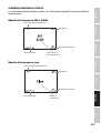
DIMENSIONS (mm) 109
CARACTÉRISTIQUES TECHNIQUES 110
EXPLICATIONS RELATIVES À L’INDICE DE PROTECTIONIP 112
DISTANCE MINIMALE PAR RAPPORT À LA SURFACE ÉCLAIRÉE 112
DISTANCE MINIMALE PAR RAPPORT AUX MATÉRIAUX NORMALEMENT INFLAMMABLES 113
ÉLIMINATION 113
DÉCLARATIONS DU FABRICANT 114
ESPAÑOL
INFORMACIÓN SOBRE ESTE MANUAL DE INSTRUCCIONES 115
USO PREVISTO 115
TÉRMINOS Y SÍMBOLOS 115
INSTRUCCIONES DE SEGURIDAD 116
INDICACIONES PARA EQUIPOS PORTÁTILES DE EXTERIOR 121
VOLUMEN DE SUMINISTRO 122
INTRODUCCIÓN 122

CONEXIONES, ELEMENTOS DE MANEJO Y ELEMENTOS DE VISUALIZACIÓN 123
FUNCIONAMIENTO 126
ESTADO W-DMX™ 128
INSTALACIÓN Y MONTAJE 137
CUIDADO, MANTENIMIENTO Y REPARACIÓN 137
CAMBIO DE LA LÁMPARA 139
AJUSTE DE LA LÁMPARA 141
CAMBIO DE GOBOS 143
DIMENSIONES (mm) 147
DATOS TÉCNICOS 148
EXPLICACIÓN SOBRE LA CLASE DE PROTECCIÓN IP 150
DISTANCIA MÍNIMA CON RESPECTO A LA SUPERFICIE ILUMINADA 151
DISTANCIA MÍNIMA CON RESPECTO A MATERIALES NORMALMENTE INFLAMABLES 151
ELIMINACIÓN 151
DECLARACIONES DEL FABRICANTE 152
POLSKI
INFORMACJE DOTYCZĄCE NINIEJSZEJ INSTRUKCJI OBSŁUGI 153
UŻYTKOWANIE ZGODNE Z PRZEZNACZENIEM 153
OBJAŚNIENIA TERMINÓW I SYMBOLI 153
ZASADY BEZPIECZEŃSTWA 154
UWAGI DOTYCZĄCE PRZENOŚNEGO SPRZĘTU ZEWNĘTRZNEGO 160
ZAKRES DOSTAWY 160
WPROWADZENIE 160
PRZYŁĄCZA, ELEMENTY OBSŁUGI I WSKAŹNIKI 161
OBSŁUGA 164
STATUS W-DMX™ 166
USTAWIANIE I MONTAŻ 174
CZYSZCZENIE, KONSERWACJA I NAPRAWY 175
WYMIANA ŹRÓDŁA ŚWIATŁA 177
REGULACJA LAMPY 179
WYMIANA TARCZY GOBO 181
WYMIARY (mm) 184
DANE TECHNICZNE 185
OBJAŚNIENIA DOTYCZĄCE STOPNIA OCHRONY IP 187
MINIMALNA ODLEGŁOŚĆ OD POWIERZCHNI OŚWIETLONEJ 187
MINIMALNA ODLEGŁOŚĆ OD NORMALNIE ŁATWOPALNYCH MATERIAŁÓW 187
UTYLIZACJA 188
OŚWIADCZENIA PRODUCENTA 189
INFORMAZIONI SUL PRESENTE MANUALE D'USO 190
UTILIZZO CONFORME 190

ITALIANO
SPIEGAZIONE DI CONCETTI E SIMBOLI 190
INDICAZIONI SULLA SICUREZZA 191
AVVERTENZE PER DISPOSITIVI PORTATILI PER ESTERNI 196
VOLUME DI CONSEGNA 197
INTRODUZIONE 197
CONNETTORI, ELEMENTI DI COMANDO E VISUALIZZAZIONE 198
UTILIZZO 200
STATO W-DMX™ 203
INSTALLAZIONE E MONTAGGIO 211
PULIZIA, MANUTENZIONE E RIPARAZIONE 212
SOSTITUZIONE DELLA LAMPADA 213
REGOLAZIONE DELLA LAMPADA 215
SOSTITUZIONE DEI GOBO 217
DIMENSIONI (mm) 220
DATI TECNICI 221
SPIEGAZIONI SULLA PROTEZIONE IP 223
DISTANZA MINIMA DALLA SUPERFICIE ILLUMINATA 223
DISTANZA MINIMA DAI MATERIALI NORMALMENTE INFIAMMABILI 223
SMALTIMENTO 224
DICHIARAZIONI DEL PRODUTTORE 225
DMX
DMX CONTROL / DMX STEUERUNG / PILOTAGE DMX / CONTROL DMX /
STEROWANIE DMX / CONTROLLO DMX 226
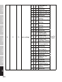
PIXEL SEGMENTS / PIXEL SEGMENTE 233

6
DMX
ITALIANO
POLSKI
ESPAÑOL
FRANCAIS
DEUTSCHENGLISH
ENGLISH
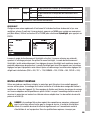
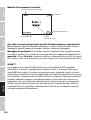
YOU HAVE MADE THE RIGHT CHOICE!
This device has been developed and manufactured to the highest quality standards to ensure
many years of problem-free operation. Please read this user manual carefully to be able to use
your new Cameo product quickly and optimally. Further information about Cameo Light is avail-
able on our website CAMEOLIGHT.COM.
INFORMATION ON THIS USER MANUAL
• Carefully read the safety instructions and the entire manual before operating the device.
• Observe the warnings on the device and in the user manual.
• Always keep the user manual within reach.
• If you sell or pass on the device, it is important that you also include this user manual, as it is an
integral part of the product.
INTENDED USE
The product is a device for event technology!
This product has been developed for professional use in the field of event technology and is not
suitable for use as domestic lighting!
Furthermore, this product is only intended for qualified users with specialist knowledge of event
technology!
Use of the product outside the specified technical data and operating conditions is considered
inappropriate!
Liability for damage and third-party damage to persons and property due to inappropriate use is
excluded!
The product is not suitable for:
• Use by persons (including children) with limited physical, sensory or mental abilities or lack of
experience and knowledge.
• children (children must be instructed not to play with the device).
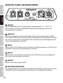
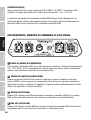
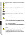
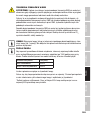
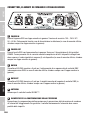
DEFINITIONS AND SYMBOL EXPLANATIONS
1. HAZARD: The word HAZARD, possibly in combination with a symbol, indicates situations in
which there is an immediate danger or risk of potentially fatal injury.
2. WARNING: The word WARNING, possibly in combination with a symbol, indicates situations in
which there is an immediate danger or risk of potentially fatal injury.
3. CAUTION: The word CAUTION, possibly in combination with a symbol, indicates situations or
conditions that could result in injury.
4. ATTENTION: The word ATTENTION, possibly in combination with a symbol, indicates situations
or conditions that could result in damage to property and/or the environment.

7
DMX DEUTSCHFRANCAIS
ESPAÑOL ENGLISH
ITALIANO POLSKI
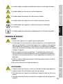
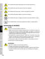
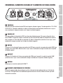
This symbol identifies hazards that can cause electric shock.
This symbol identifies hazardous areas or hazardous situations.
This symbol indicates hazards caused by hot surfaces.
This symbol indicates hazards caused by intense light sources.
This symbol indicates a device in which there are no user-replaceable parts.
This symbol indicates additional information on the operation of the product.
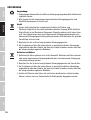
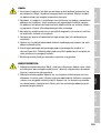
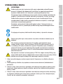
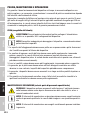
SAFETY INSTRUCTIONS
HAZARD:
1. Do not open the device and do not perform any modifications.
2. If your device no longer functions properly, if liquids or objects get inside it or if it
has been damaged in any other way, switch it off immediately and unplug it from
the power source. The device may be repaired only by authorised repair techni-
cians.
3. For devices of protection class 1, the protective conductor must be connected
correctly. Never disconnect the protective conductor. Devices of protection class 2
do not have a protective conductor.
4. Ensure that live cables are not kinked or otherwise mechanically damaged.
5. Never bypass the device fuse.
WARNING:
1. The device may not be operated if it shows obvious signs of damage.
2. The device may only be installed in a voltage-free state.
3. If the device's power cable is damaged, the device may not be used.
4. Permanently connected power cables may only be replaced by a qualified person.

8
DMX
ITALIANO
POLSKI
ESPAÑOL
FRANCAIS
DEUTSCHENGLISH
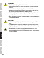
ATTENTION:
1. Do not switch on the device if it has been exposed to extreme temperature fluctu-
ations (for example, following transport). Moisture and condensation can damage
the device. Switch on the device only when it has reached room temperature.
2. Ensure that the voltage and frequency of the mains supply match the values spec-
ified on the device. If the device has a voltage selector switch, do not connect the
device until it has been set correctly. Use only suitable power cables.
3. To disconnect the device from the mains on all poles, it is not sufficient to press the
on/off switch on the device.
4. Make sure that the fuse used corresponds to the type printed on the device.
5. Ensure that suitable measures have been taken against overvoltage (e.g. lightning
strikes).
6. Observe the specified maximum output current on devices with a Power Out con-
nection. Ensure that the total current consumption of all connected devices does
not exceed the specified value.
7. Replace plug-in power cables with original cables only.
HAZARD:
1. Choking hazard! Plastic bags and small parts must be kept out of reach of persons
(including children) with reduced physical, sensory or mental capabilities.
2. Risk of falling! Make sure that the device is securely installed and will not fall
down. Only use suitable stands or mounts (particularly for fixed installations).
Ensure that accessories are properly installed and secured. Ensure that applicable
safety regulations are observed.
WARNING:
1. Use the device in the prescribed manner only.
2. Operate the device using only accessories of the type recommended and supplied
by the manufacturer.
3. Observe safety regulations applicable in your country during installation.
4. After connecting the device, ensure that all cables are routed so as to avoid dam-
age or accidents, such as from tripping.
5. Always observe the specified minimum distance to normally flammable materials!
Unless explicitly stated, the minimum distance is 0.3 m.
6. Always observe the minimum distance to the illuminated surface, which can be
read on the device!

9
DMX DEUTSCHFRANCAIS
ESPAÑOL ENGLISH
ITALIANO POLSKI
CAUTION:
1. Moving components such as mounting brackets may become jammed.
2. In the case of devices with motor-driven components, there is a risk of injury due
to the movement of the device. Sudden movement of the device can cause shock
reactions.
3. The housing surface of the device can become very hot during regular operation.
Ensure that accidental touching of the housing is not possible. Always allow the
device to cool sufficiently before removal, maintenance work and charging etc.
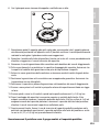
ATTENTION:
1. Do not install or use the device in the vicinity of radiators, accumulators, stoves, or
other heat sources. Ensure that the device is always installed in such a way that it
is sufficiently cooled and cannot overheat.
2. Do not place any ignition sources, such as burning candles, near the device.
3. Ventilation openings must not be covered and fans must not be blocked.
4. For transport, use the original packaging or packaging provided by the manufactur-
er.
5. Avoid any impacts to or shaking of the device.
6. Observe the IP rating and the ambient conditions such as temperature and humidi-
ty according to the specifications.
7. Devices can be continuously further developed. In the event of deviating informa-
tion on operating conditions, performance or other device properties between the
user manual and the device labelling, the information on the device always has
priority.
8. The device is not suitable for tropical climate zones or for operation over 2,000 m
above sea level.
9. Unless explicitly stated, the device is not suitable for operation under marine
conditions.
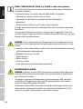
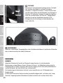
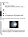
CAUTION! IMPORTANT INFORMATION REGARDING LIGHTING PRODUCTS!
1. Never look directly into the beam of light, not even for a short period of time.
2. Never look into the beam of light using optical devices such as a magnifying glass.
3. Stroboscopic effects may cause epileptic seizures in susceptible individuals!
CAUTION! IMPORTANT INFORMATION REGARDING SPOTLIGHTS WITH DISCHARGE LAMP
Observe the safety instructions in the sections
“REPLACING THE LAMP” and “CALIBRATING THE LAMP”!

10
DMX
ITALIANO
POLSKI
ESPAÑOL
FRANCAIS
DEUTSCHENGLISH
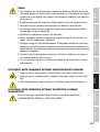
SIGNAL TRANSMISSION BY RADIO (e.g. W-DMX or audio radio systems):
The quality and performance of wireless signal transmissions generally depends on
the ambient conditions.
The following factors can impact range and signal stability, for example:
• Shielding (e.g. masonry, metal structures, water)
• High volume of radio traffic (e.g. powerful wireless LAN networks)
• Interference
• Electromagnetic radiation (e.g. LED video screens, dimmers)
All range specifications refer to free-field application with visual contact and without
interference!
The operation of transmission systems is subject to official regulations. These may
vary from region to region and must be checked by the operator before use (e.g. radio
frequency and transmission power).
WARNING: Devices with wireless signal transmission are not suitable for use in sen-
sitive areas in which radio operation can lead to potential detrimental effects. These
include:
• Hospitals, health centres or other healthcare facilities that provide patient treatment
with skilled personnel and equipment.
• Hazardous areas Class I, II and III
• Restricted areas
• Military facilities
• Aircraft or vehicles
• Areas where the use of mobile phones is prohibited
TRANSMISSION VIA W-DMX
WARNING: In general, wireless DMX transmission must not be used for applications
involving safety-related factors that might result in personal injury or property dam-
age in the event of a failure.
This applies in particular to moving scene or traverse structures, DMX-controlled
motors/lifts or lifting devices for operating DMX-operated platform lifts, hydraulic
systems or comparable moving components.
Furthermore, wireless DMX transmission must not be used to trigger flame or pyro-
technic devices, explosion-driven effects, or to control gas or liquid effects. These
include CO2 cannons, confetti shooters, water effects or similar.

11
DMX DEUTSCHFRANCAIS
ESPAÑOL ENGLISH
ITALIANO POLSKI
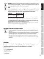
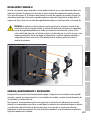
CAUTION! Switching off the lamp shortly after switching on is prevented by a delay
circuit to protect the lamp (approx. 1 minute)! Do not disconnect the device from the
power supply before the switch-off process is complete!
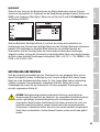
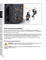
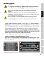
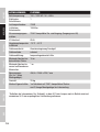
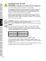
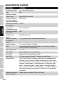
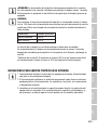
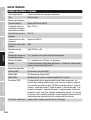
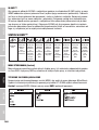
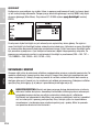
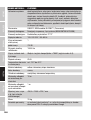
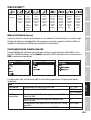
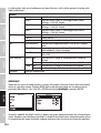
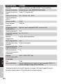
LAMP
In order to keep the device in perfect working order, it is recommended that the lamp
is replaced after 1,500 hours of operation, at the latest, by qualified service person-
nel. When replacing lamps, use only the model specified in the data sheet!
Conditions Operating time
Rated output power 1500 h
Max. service life* 3000 h
The service life of the lamp is influenced by the number of times it is switched on.
It is recommended to run the lamp for at least 15 minutes after switch-on to com-
plete the chemical cycle of the lamp and increase its life.
*Definition of service life: The time at which 50% of the lamps are still in operation
and deliver at least 50% of the original light output.
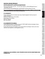
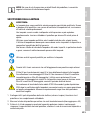
NOTES ON PORTABLE OUTDOOR DEVICES
1. Temporary operation! Event equipment is generally only designed for temporary
operation.
2. Continuous operation or permanent structural installation – particularly outdoors –
can impair the function, surfaces and seals and accelerate material fatigue.
3. Damage to the surface coating can impair the device's corrosion protection.
Damaged surface coating (e.g. scratches) must be promptly repaired by suitable
measures.
INCLUDED
Remove the product from the packaging and remove all packaging material.
Please check the completeness and integrity of the delivery and notify your distribution partner
immediately after purchase if the delivery is not complete or if it is damaged.
Product includes:
• OTOS H5 moving head
• 1 x power cable
• 2 Omega brackets
• User manual

12
DMX
ITALIANO
POLSKI
ESPAÑOL
FRANCAIS
DEUTSCHENGLISH
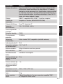
INTRODUCTION
PROFESSIONAL OUTDOOR DISCHARGE MOVING HEAD
CLOTOSH5
CONTROL FUNCTIONS:
26 and 32-channel DMX control
Master/slave operation
Standalone operation
W-DMX™
FEATURES:
Protection class IP65. 480 W discharge lamp. DMX512. W-DMX™. 5-pin DMX connections.
2 x Omega mounting brackets included. Operating voltage: 100–240 V AC.
The spotlight features the RDM standard (Remote Device Management). Remote device
management allows the user to view the status and configuration of RDM terminals via an RDM-
capable controller.
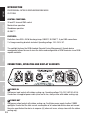
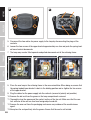
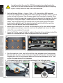
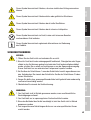
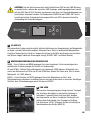
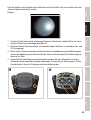
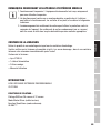
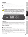
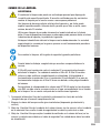
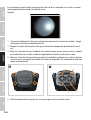
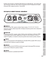
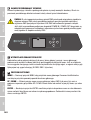
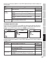
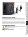
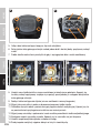
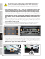
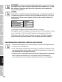
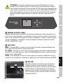
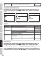
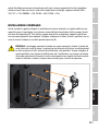
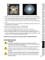
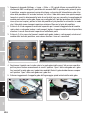
CONNECTIONS, OPERATING AND DISPLAY ELEMENTS
3 4
56
1 2
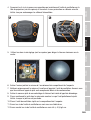
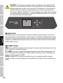
1 POWER IN
IP65 power input socket with rubber sealing cap. Operating voltage 100–240 V AC/50–60 Hz.
Connection via supplied power cable (when not in use, always close with rubber sealing cap).
2 POWER OUT
IP65 power output socket with rubber sealing cap. Facilitates power supply to other CAMEO
spotlights. Ensure that the total current consumption of all connected devices does not exceed
the value specified on the device in amperes (A) (when not in use, always close with the rubber
sealing cap).

13
DMX DEUTSCHFRANCAIS
ESPAÑOL ENGLISH
ITALIANO POLSKI
3 DMX IN
Male IP65 5-pin XLR socket for connecting a DMX control device (e.g. DMX console; when not in
use, always close with the rubber sealing cap).
4 DMX OUT
Female IP65 5-pin XLR socket for sending DMX control signal (when not in use, always close with
the rubber sealing cap).
5 ANTENNA
Antenna for W-DMX™ control.
6 PRESSURE EQUALISATION ELEMENT
Pressure equalisation element to prevent condensation inside the housing. In order to ensure its
proper function, the element must be protected from contamination.
ATTENTION: In order to provide protection from spraying water, in accordance with
protection class IP65, special IP65-rated XLR connectors must be used correctly with the
DMX input and output sockets, or they must be closed using the rubber sealing caps.
When connected correctly, or when sealed correctly with the rubber sealing caps, the
POWER IN and POWER OUT sockets are protected from spraying water, as in accordance
with IP65.
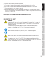
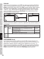
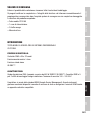
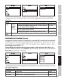
MENU
UP
DOWN
ENTER
7
8
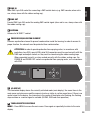
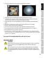
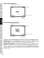
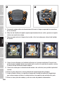
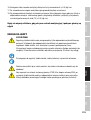
7 LC-DISPLAY
The illuminated display shows the currently activated mode (main display), the menu items in the
main menu and sub-menus and the numerical value or status in certain menu items. If there is no
control signal to the device, the characters in the centre of the display start flashing; the flashing
stops as soon as a control signal is available (W-DMX, DMX and slave operation).
8 TOUCH-SENSITIVE CONTROLS
MENU – Press MENU to access the main menu. Press again or repeatedly to return to the main
display.

14
DMX
ITALIANO
POLSKI
ESPAÑOL
FRANCAIS
DEUTSCHENGLISH
UP and DOWN – Select the menu items in the main menu (DMX address, operating mode, etc.)
and in the sub-menus using UP and DOWN. Change the status or value in a menu item, e.g. DMX
address.
ENTER – Press ENTER to access the menu level to make value or status changes, and to access
one of the sub-menus. Confirm value or status changes by pressing ENTER.
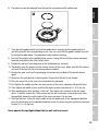
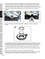
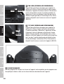
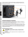
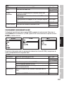
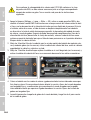
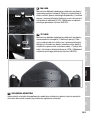
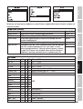
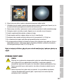
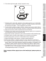
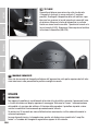
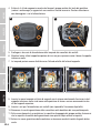
9
LOCK UNLOCK
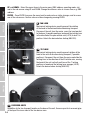
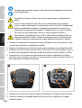
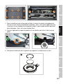
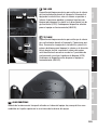
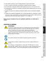
9 PAN LOCK
Mechanical locking device used to prevent the rotation
of the head in the horizontal direction during transport.
Disconnect the unit from the mains, move the head parallel
to the base (4 possible positions) and push the locking lever
in the direction of the pan rotation axis (LOCK) to lock it in
position. Unlock the device before startup (UNLOCK).
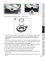
10
LOCK
UNLOCK
10 TILT LOCK
Mechanical locking device used to prevent rotation of the
head in the vertical direction during transport (7 possible
positions). Disconnect the unit from the mains and slide the
locking lever in the direction of the tilt rotation axis, moving
the head of the unit vertically until one of the 7 locking
positions is found and the locking lever engages (LOCK).
Unlock the device before startup (UNLOCK).
11
11
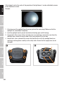
11 RECESSED GRIPS
In addition to the two transport handles on the base of the unit, there are practical recessed grips
at the top of the inner sides of the two device arms.

15
DMX DEUTSCHFRANCAIS
ESPAÑOL ENGLISH
ITALIANO POLSKI
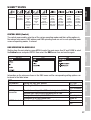
OPERATION
NOTES
As soon as the spotlight is correctly connected to the mains supply, “Welcome to Cameo”, the
model name and the software version will be displayed in succession during the start process and
motor reset. After this process, the spotlight is ready for operation and the previously activated
operating mode is launched.
The main display is activated automatically if no input is made within approximately 30 seconds.
In the event of a technical fault, the lamp is switched off, the display shows “Lamp Protected”
and the warning triangle symbol appears in the bottom right-hand corner.
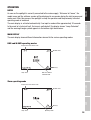
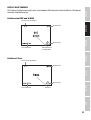
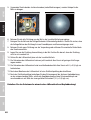
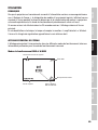
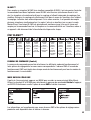
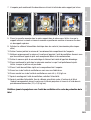
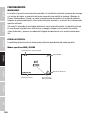
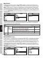
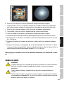
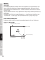
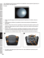
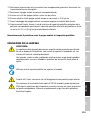
MAIN DISPLAY
The main display shows different information relevant to the various operating modes.
DMX and W-DMX operating modes
Temperature of the device head
W-DMX status
Warning
Lamp status DMX start address
and DMX mode
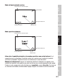
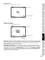
Slave operating mode
Temperature of the device head
W-DMX status
Warning
Lamp status Operating mode

16
DMX
ITALIANO
POLSKI
ESPAÑOL
FRANCAIS
DEUTSCHENGLISH
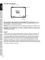
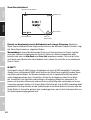
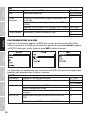
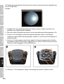
Standalone operating mode
Temperature of the device head
W-DMX status
Warning
Lamp status Scene and
signal output
Note regarding the main display in operating modes with external control: As soon as
the control signal is interrupted, the characters in the centre of the display begin to flash. The
flashing stops when a control signal is present.
Warning: If the warning symbol (triangle with exclamation mark) appears in the display, there is
a fault with one or more components in the device. The affected components can be seen in the
Info Menu under Error Info. If the error cannot be rectified by a restart or reset, please contact
an authorised service centre.
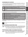
W-DMX™
To pair a W-DMX receiver with a W-DMX compatible transmitter, the Reset command must be
executed in the menu item WDMX under Receiver (select and confirm Reset). The receiver is
now in pairing standby and waiting for a pairing request from a transmitter. Start the pairing
by selecting Link in the menu of the transmitter and confirming; the pairing now takes place
automatically. In the same way, several receivers can be paired simultaneously or one after
the other to a transmitter (e.g. for master / slave operation). A W-DMX connection is always
maintained until the connection is disconnected by means of the Reset command in the receiver
or the Unlink command in the transmitter, regardless of whether a device has been disconnected
from the power supply in the meantime.

17
DMX DEUTSCHFRANCAIS
ESPAÑOL ENGLISH
ITALIANO POLSKI
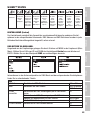
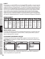
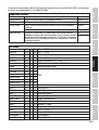
W-DMX™ STATUS
W-DMX
deactivated
W-DMX
as receiver
activated,
not paired
W-DMX
as receiver
activated
and
paired,
Transmitter
switched off
or out of
range
W-DMX
as receiver
activated
and
paired,
no
DMX signal
W-DMX
as receiver
activated
and
paired,
DMX signal
is present
W-DMX
as trans-
mitter
with G3
standard
activated,
DMX signal
is present
W-DMX
as trans-
mitter
with G4s
standard
activated,
DMX signal
is present
W-DMX
as trans-
mitter
with G3
standard
activated,
no
DMX signal
W-DMX
as trans-
mitter
with G4s
standard
activated,
no
DMX signal
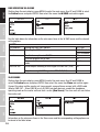
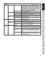
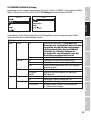
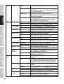
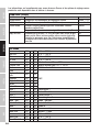
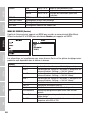
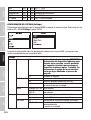
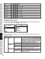
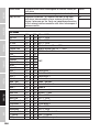
CONTROL MENU (Control)
The control menu enables selection of the various operating modes and their setting options in
the relevant sub-menus. DMX address and DMX operating mode are set in each operating mode
across all operating modes, if relevant.
DMX OPERATION VIA DMX CABLE
Starting from the main display, press MENU to enter the main menu. Use UP and DOWN to select
the Control menu and press ENTER. Now select the DMX menu item and confirm again.
Information on the sub-menu items in the DMX menu and the corresponding setting options can
be found in the table below.
DMX
DMX Address Setting the DMX start address 001–486
Mode Selecting the DMX mode 26CH Standard
32CH Extended
W-DMX
Transmitter Deactivate sending of the DMX control signal via W-DMX Off
Activate DMX control signal forwarding via W-DMX On
Pairing with ready-to-pair W-DMX devices Force to pair
Disconnect all W-DMX connections Unlink All
W-DMX standard Selection of the W-DMX transmission standard G3
G4s

18
DMX
ITALIANO
POLSKI
ESPAÑOL
FRANCAIS
DEUTSCHENGLISH
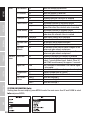
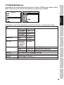
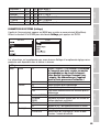
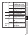
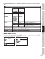
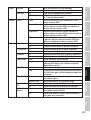
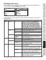
DMX OPERATION VIA W-DMX
Starting from the main display, press MENU to enter the main menu. Use UP and DOWN to select
the Control menu and press ENTER. Now select the menu itemW-DMX and confirm again.
See the table below for information on the sub-menu items in the W-DMX menu and the relevant
setting options.
W-DMX
DMX Address Setting the DMX start address 001–486
Mode Selecting the DMX mode 26CH Standard
32CH Extended
Receive Deactivate reception via W-DMX Off
Activate reception via W-DMX On
Disconnect all connections and place in pairing standby
mode Unlink
DMX XLR Out Do not output incoming W-DMX signal via DMX OUT (XLR) Off
Output incoming W-DMX signal via DMX OUT (XLR) On
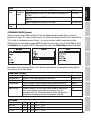
SLAVE MODE
Starting from the main display, press MENU to enter the main menu. Use UP and DOWN to
select the Control menu and press ENTER. Now select the menu item Slave and confirm again.
Connect the slave and the master unit (same model, same software version) with a DMX cable
(Master DMX OUT – Slave DMX IN) or via W-DMX (pair both devices), enable the standalone
operating mode on the master unit and start a scene (Run Scene). The slave unit will now follow
the master unit.
Information on the sub-menu items in the Slave menu and the corresponding setting options can
be found in the table below.

19
DMX DEUTSCHFRANCAIS
ESPAÑOL ENGLISH
ITALIANO POLSKI
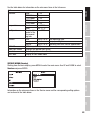
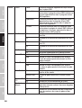
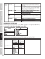
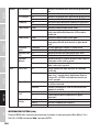
Slave
Receive
Mode Set
reception
mode
Signal reception exclusively via DMX IN XLR Only
Signal reception via DMX IN, with signal interruption via
W-DMX XLR First
Signal reception via W-DMX, with signal interruption via
DMX IN Wireless First
Signal reception exclusively via W-DMX Wireless Only
Wireless
Reset Disconnect all connections and place in pairing standby mode
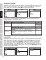
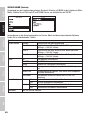
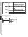
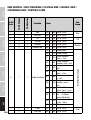
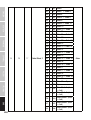
STANDALONE MODE (Scenes)
Similar to when using a DMX control unit, the standalone operating mode Scenes makes it
possible to set pan, tilt, zoom, pan/tilt macros etc. directly on the device with values from 000 to
255. A total of 8 individual scenes (Scene 1–8) can be created, edited, saved and recalled.
Starting from the main display, press MENU to enter the main menu. Use UP and DOWN to select
the Control menu and press ENTER. Now select the menu item Stand Alone and confirm again.
Information on the sub-menu items in the Scenes menu and the corresponding setting options
can be found in the table below.
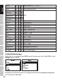
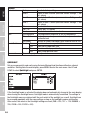
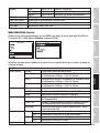
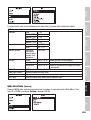
Stand Alone (Scenes)
Run Scene Start Scene Scene 1–8
Record Scene Record a scene from an external controller Scene 1–8
Edit Scene Edit scene (see table Edit Scene) Scene 1–8
Master/Alone Output scene as control signal to one or more slave units Master
Do not output scene as control signal (Alone) Alone
Copy to Slave Transfer scenes 1 to 8 via DMX cable to one or more slave
units (same model, same software version). Carry out
procedure with Yes. The scene memory of the slave units is
completely overwritten. Cancel the operation with No.
No
Yes
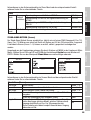
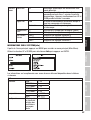
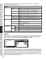
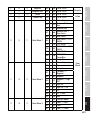
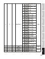
Edit Scene
Pan 000 – 255 0% -> 100%
Pan Fine: 000 – 255 0% -> 100%
Tilt 000 – 255 0% -> 100%
Tilt Fine 000 – 255 0% -> 100%

20
DMX
ITALIANO
POLSKI
ESPAÑOL
FRANCAIS
DEUTSCHENGLISH
Dimmer 000 – 255 Master dimmer 0% -> 100%
Dimmer Fine 000 – 255 Master dimmer fine 0% -> 100%
Strobe 000 – 255 Multi-functional strobe
Cyan 000 – 255
CMY
Cyan Fine 000 – 255
Magenta 000 – 255
Magenta Fine 000 – 255
Yellow 000 – 255
Yellow Fine 000 – 255
Colour 1 000 – 255 Colour Wheel 1
Colour 2 000 – 255 Colour Wheel 2
Colour 3 000 – 255 Colour Wheel 3
Gobo 1 000 – 255 Gobo Wheel 1
Gobo 1 Rot. 000 – 255 Gobo 1 Rotation
Gobo 1 Rot. F. 000 – 255 Gobo 1 Rotation Fine
Gobo 2 000 – 255 Gobo Fix
Zoom 000 – 255 Narrow -> wide
Zoom Fine 000 – 255 Narrow -> wide
Focus 000 – 255 0% -> 100%
Focus Fine 000 – 255 0% -> 100%
Prism Wheel 1 000 – 255 Prism Wheel 1
Prism Wheel 2 000 – 255 Prism Wheel 2
Frost 000 – 255 0% -> 100%
Animation 000 – 255 0% -> 100%
Animation Rot. 000 – 255 Animation Wheel Rotation
P/T Macro 000 – 255 Pan/Tilt Macro
P/T Speed 000 – 255 Pan/Tilt Macro Speed
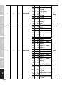
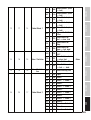
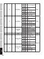
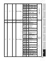
SYSTEM SETTINGS (Settings)
Starting from the main display, press MENU to enter the main menu. Use UP and DOWN to select
Settings and press ENTER.
Information on the sub-menu items in the Settings menu and the corresponding setting options
can be found in the table below.
La page est en cours de chargement...
La page est en cours de chargement...
La page est en cours de chargement...
La page est en cours de chargement...
La page est en cours de chargement...
La page est en cours de chargement...
La page est en cours de chargement...
La page est en cours de chargement...
La page est en cours de chargement...
La page est en cours de chargement...
La page est en cours de chargement...
La page est en cours de chargement...
La page est en cours de chargement...
La page est en cours de chargement...
La page est en cours de chargement...
La page est en cours de chargement...
La page est en cours de chargement...
La page est en cours de chargement...
La page est en cours de chargement...
La page est en cours de chargement...
La page est en cours de chargement...
La page est en cours de chargement...
La page est en cours de chargement...
La page est en cours de chargement...
La page est en cours de chargement...
La page est en cours de chargement...
La page est en cours de chargement...
La page est en cours de chargement...
La page est en cours de chargement...
La page est en cours de chargement...
La page est en cours de chargement...
La page est en cours de chargement...
La page est en cours de chargement...
La page est en cours de chargement...
La page est en cours de chargement...
La page est en cours de chargement...
La page est en cours de chargement...
La page est en cours de chargement...
La page est en cours de chargement...
La page est en cours de chargement...
La page est en cours de chargement...
La page est en cours de chargement...
La page est en cours de chargement...
La page est en cours de chargement...
La page est en cours de chargement...
La page est en cours de chargement...
La page est en cours de chargement...
La page est en cours de chargement...
La page est en cours de chargement...
La page est en cours de chargement...
La page est en cours de chargement...
La page est en cours de chargement...
La page est en cours de chargement...
La page est en cours de chargement...
La page est en cours de chargement...
La page est en cours de chargement...
La page est en cours de chargement...
La page est en cours de chargement...
La page est en cours de chargement...
La page est en cours de chargement...
La page est en cours de chargement...
La page est en cours de chargement...
La page est en cours de chargement...
La page est en cours de chargement...
La page est en cours de chargement...
La page est en cours de chargement...
La page est en cours de chargement...
La page est en cours de chargement...
La page est en cours de chargement...
La page est en cours de chargement...
La page est en cours de chargement...
La page est en cours de chargement...
La page est en cours de chargement...
La page est en cours de chargement...
La page est en cours de chargement...
La page est en cours de chargement...
La page est en cours de chargement...
La page est en cours de chargement...
La page est en cours de chargement...
La page est en cours de chargement...
La page est en cours de chargement...
La page est en cours de chargement...
La page est en cours de chargement...
La page est en cours de chargement...
La page est en cours de chargement...
La page est en cours de chargement...
La page est en cours de chargement...
La page est en cours de chargement...
La page est en cours de chargement...
La page est en cours de chargement...
La page est en cours de chargement...
La page est en cours de chargement...
La page est en cours de chargement...
La page est en cours de chargement...
La page est en cours de chargement...
La page est en cours de chargement...
La page est en cours de chargement...
La page est en cours de chargement...
La page est en cours de chargement...
La page est en cours de chargement...
La page est en cours de chargement...
La page est en cours de chargement...
La page est en cours de chargement...
La page est en cours de chargement...
La page est en cours de chargement...
La page est en cours de chargement...
La page est en cours de chargement...
La page est en cours de chargement...
La page est en cours de chargement...
La page est en cours de chargement...
La page est en cours de chargement...
La page est en cours de chargement...
La page est en cours de chargement...
La page est en cours de chargement...
La page est en cours de chargement...
La page est en cours de chargement...
La page est en cours de chargement...
La page est en cours de chargement...
La page est en cours de chargement...
La page est en cours de chargement...
La page est en cours de chargement...
La page est en cours de chargement...
La page est en cours de chargement...
La page est en cours de chargement...
La page est en cours de chargement...
La page est en cours de chargement...
La page est en cours de chargement...
La page est en cours de chargement...
La page est en cours de chargement...
La page est en cours de chargement...
La page est en cours de chargement...
La page est en cours de chargement...
La page est en cours de chargement...
La page est en cours de chargement...
La page est en cours de chargement...
La page est en cours de chargement...
La page est en cours de chargement...
La page est en cours de chargement...
La page est en cours de chargement...
La page est en cours de chargement...
La page est en cours de chargement...
La page est en cours de chargement...
La page est en cours de chargement...
La page est en cours de chargement...
La page est en cours de chargement...
La page est en cours de chargement...
La page est en cours de chargement...
La page est en cours de chargement...
La page est en cours de chargement...
La page est en cours de chargement...
La page est en cours de chargement...
La page est en cours de chargement...
La page est en cours de chargement...
La page est en cours de chargement...
La page est en cours de chargement...
La page est en cours de chargement...
La page est en cours de chargement...
La page est en cours de chargement...
La page est en cours de chargement...
La page est en cours de chargement...
La page est en cours de chargement...
La page est en cours de chargement...
La page est en cours de chargement...
La page est en cours de chargement...
La page est en cours de chargement...
La page est en cours de chargement...
La page est en cours de chargement...
La page est en cours de chargement...
La page est en cours de chargement...
La page est en cours de chargement...
La page est en cours de chargement...
La page est en cours de chargement...
La page est en cours de chargement...
La page est en cours de chargement...
La page est en cours de chargement...
La page est en cours de chargement...
La page est en cours de chargement...
La page est en cours de chargement...
La page est en cours de chargement...
La page est en cours de chargement...
La page est en cours de chargement...
La page est en cours de chargement...
La page est en cours de chargement...
La page est en cours de chargement...
La page est en cours de chargement...
La page est en cours de chargement...
La page est en cours de chargement...
La page est en cours de chargement...
La page est en cours de chargement...
La page est en cours de chargement...
La page est en cours de chargement...
La page est en cours de chargement...
La page est en cours de chargement...
La page est en cours de chargement...
La page est en cours de chargement...
La page est en cours de chargement...
La page est en cours de chargement...
La page est en cours de chargement...
La page est en cours de chargement...
La page est en cours de chargement...
La page est en cours de chargement...
La page est en cours de chargement...
La page est en cours de chargement...
La page est en cours de chargement...
La page est en cours de chargement...
La page est en cours de chargement...
La page est en cours de chargement...
La page est en cours de chargement...
La page est en cours de chargement...
La page est en cours de chargement...
La page est en cours de chargement...
La page est en cours de chargement...
La page est en cours de chargement...
La page est en cours de chargement...
La page est en cours de chargement...
La page est en cours de chargement...
-
 1
1
-
 2
2
-
 3
3
-
 4
4
-
 5
5
-
 6
6
-
 7
7
-
 8
8
-
 9
9
-
 10
10
-
 11
11
-
 12
12
-
 13
13
-
 14
14
-
 15
15
-
 16
16
-
 17
17
-
 18
18
-
 19
19
-
 20
20
-
 21
21
-
 22
22
-
 23
23
-
 24
24
-
 25
25
-
 26
26
-
 27
27
-
 28
28
-
 29
29
-
 30
30
-
 31
31
-
 32
32
-
 33
33
-
 34
34
-
 35
35
-
 36
36
-
 37
37
-
 38
38
-
 39
39
-
 40
40
-
 41
41
-
 42
42
-
 43
43
-
 44
44
-
 45
45
-
 46
46
-
 47
47
-
 48
48
-
 49
49
-
 50
50
-
 51
51
-
 52
52
-
 53
53
-
 54
54
-
 55
55
-
 56
56
-
 57
57
-
 58
58
-
 59
59
-
 60
60
-
 61
61
-
 62
62
-
 63
63
-
 64
64
-
 65
65
-
 66
66
-
 67
67
-
 68
68
-
 69
69
-
 70
70
-
 71
71
-
 72
72
-
 73
73
-
 74
74
-
 75
75
-
 76
76
-
 77
77
-
 78
78
-
 79
79
-
 80
80
-
 81
81
-
 82
82
-
 83
83
-
 84
84
-
 85
85
-
 86
86
-
 87
87
-
 88
88
-
 89
89
-
 90
90
-
 91
91
-
 92
92
-
 93
93
-
 94
94
-
 95
95
-
 96
96
-
 97
97
-
 98
98
-
 99
99
-
 100
100
-
 101
101
-
 102
102
-
 103
103
-
 104
104
-
 105
105
-
 106
106
-
 107
107
-
 108
108
-
 109
109
-
 110
110
-
 111
111
-
 112
112
-
 113
113
-
 114
114
-
 115
115
-
 116
116
-
 117
117
-
 118
118
-
 119
119
-
 120
120
-
 121
121
-
 122
122
-
 123
123
-
 124
124
-
 125
125
-
 126
126
-
 127
127
-
 128
128
-
 129
129
-
 130
130
-
 131
131
-
 132
132
-
 133
133
-
 134
134
-
 135
135
-
 136
136
-
 137
137
-
 138
138
-
 139
139
-
 140
140
-
 141
141
-
 142
142
-
 143
143
-
 144
144
-
 145
145
-
 146
146
-
 147
147
-
 148
148
-
 149
149
-
 150
150
-
 151
151
-
 152
152
-
 153
153
-
 154
154
-
 155
155
-
 156
156
-
 157
157
-
 158
158
-
 159
159
-
 160
160
-
 161
161
-
 162
162
-
 163
163
-
 164
164
-
 165
165
-
 166
166
-
 167
167
-
 168
168
-
 169
169
-
 170
170
-
 171
171
-
 172
172
-
 173
173
-
 174
174
-
 175
175
-
 176
176
-
 177
177
-
 178
178
-
 179
179
-
 180
180
-
 181
181
-
 182
182
-
 183
183
-
 184
184
-
 185
185
-
 186
186
-
 187
187
-
 188
188
-
 189
189
-
 190
190
-
 191
191
-
 192
192
-
 193
193
-
 194
194
-
 195
195
-
 196
196
-
 197
197
-
 198
198
-
 199
199
-
 200
200
-
 201
201
-
 202
202
-
 203
203
-
 204
204
-
 205
205
-
 206
206
-
 207
207
-
 208
208
-
 209
209
-
 210
210
-
 211
211
-
 212
212
-
 213
213
-
 214
214
-
 215
215
-
 216
216
-
 217
217
-
 218
218
-
 219
219
-
 220
220
-
 221
221
-
 222
222
-
 223
223
-
 224
224
-
 225
225
-
 226
226
-
 227
227
-
 228
228
-
 229
229
-
 230
230
-
 231
231
-
 232
232
-
 233
233
-
 234
234
-
 235
235
-
 236
236


Cameo OTOS® H5 Manuel utilisateur
- Catégorie
- Projecteurs
- Taper
- Manuel utilisateur
dans d''autres langues
- italiano: Cameo OTOS® H5 Manuale utente
- English: Cameo OTOS® H5 User manual
- español: Cameo OTOS® H5 Manual de usuario
- Deutsch: Cameo OTOS® H5 Benutzerhandbuch
- polski: Cameo OTOS® H5 Instrukcja obsługi
Documents connexes
-
Cameo EVOS® W7 IP Manuel utilisateur
-
-
-
-
-
-
-
-
-