Cameo PIXBAR® 600 IP G2 Manuel utilisateur
- Catégorie
- Projecteurs
- Taper
- Manuel utilisateur

USER´S MANUAL
BEDIENUNGSANLEITUNG
MANUEL D`UTILISATION
MANUAL DE USUARIO
INSTRUKCJA OBSŁUGI
MANUALE D‘ USO
PIXBAR® G2
IP65 LED BAR
CLPB400IPG2 (RGBW) / CLPB600IPG2 (RGBWAUV)
RGBW
RGBWA

CONTENTS / INHALTSVERZEICHNIS / CONTENU /
CONTENIDO / TREŚĆ / CONTENUTO
ENGLISH
INFORMATION ON THIS USER MANUAL 6
INTENDED USE 6
DEFINITIONS AND SYMBOLS 6
SAFETY INSTRUCTIONS 7
NOTES ON PORTABLE OUTDOOR DEVICES 11
PACKAGING CONTENT 11
INTRODUCTION 11
CONNECTIONS, OPERATING AND DISPLAY ELEMENTS 13
OPERATION 14
INSTALLATION 27
FROST FILTER 32
GLARE SHIELD 32
CARE, MAINTENANCE AND REPAIR 33
OPTIONAL ACCESSORIES 34
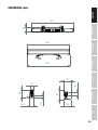
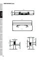
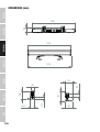
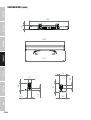
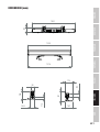
DIMENSIONS (mm) 35
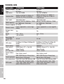
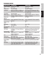
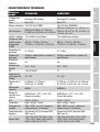
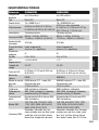
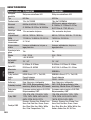
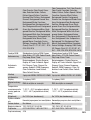
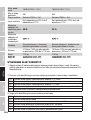
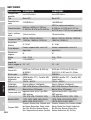
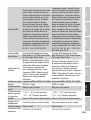
TECHNICAL DATA 36
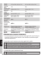
EXPLANATIONS ON IP RATING 38
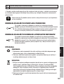
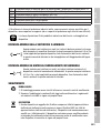
MINIMUM DISTANCE TO ILLUMINATED SURFACE 39
MINIMUM DISTANCE TO NORMALLY FLAMMABLE MATERIALS 39
DISPOSAL 39
MANUFACTURER’S DECLARATIONS 40
DEUTSCH
INFORMATIONEN ZU DIESER BEDIENUNGSANLEITUNG 41
BESTIMMUNGSGEMÄSSER GEBRAUCH 41
BEGRIFFS- UND SYMBOLERKLÄRUNGEN 41
SICHERHEITSHINWEISE 42
HINWEISE FÜR ORTSVERÄNDERLICHE OUTDOOR-GERÄTE 46
LIEFERUMFANG 46
EINFÜHRUNG 46
ANSCHLÜSSE, BEDIEN- UND ANZEIGEELEMENTE 48
BEDIENUNG 49
MONTAGE 63
FROSTFILTER 69
BLENDSCHUTZ 69
PFLEGE, WARTUNG UND REPARATUR 70

OPTIONALES ZUBEHÖR 71
ABMESSUNGEN (mm) 72
TECHNISCHE DATEN 73
ERLÄUTERUNGEN ZUR IP-SCHUTZART 75
MINDESTABSTAND ZUR BELEUCHTETEN FLÄCHE 76
MINDESTABSTAND ZU NORMAL ENTFLAMMBAREN MATERIALIEN 76
ENTSORGUNG 76
HERSTELLERERKLÄRUNGEN 77
FRANÇAIS
INFORMATIONS SUR CE MANUEL D'UTILISATION 78
UTILISATION PRÉVUE 78
DÉFINITIONS ET EXPLICATION DES PICTOGRAMMES 78
CONSIGNES DE SÉCURITÉ 79
NOTES SUR LES APPAREILS PORTABLES POUR EXTÉRIEUR 83
CONTENU DU CARTON 83
INTRODUCTION 84
CONNECTEURS, UTILISATION ET INDICATEURS 85
FONCTIONNEMENT 86
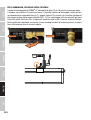
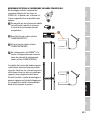
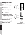
MONTAGE 100
FILTRE FROST 105
ÉCRAN ANTI-ÉBLOUISSEMENT 105
ENTRETIEN, MAINTENANCE ET RÉPARATIONS 106
ACCESSOIRES EN OPTION 107
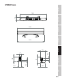
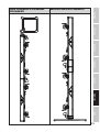
DIMENSIONS (mm) 108
CARACTÉRISTIQUES TECHNIQUES 109
EXPLICATION DE LA CLASSE DE PROTECTION IP 112
DISTANCE MINIMALE PAR RAPPORT À LA SURFACE ÉCLAIRÉE 112
DISTANCE MINIMALE PAR RAPPORT AUX MATÉRIAUX NORMALEMENT 113
INFLAMMABLES 113
MISE AU REBUT 113
DÉCLARATIONS DU FABRICANT 113

ESPAÑOL
INFORMACIÓN SOBRE ESTE MANUAL DE USUARIO 115
USO ADECUADO 115
DEFINICIONES Y EXPLICACIONES DE LOS SÍMBOLOS 115
INSTRUCCIONES DE SEGURIDAD 116
INDICACIONES PARA EQUIPOS PORTÁTILES DE EXTERIOR 120
ELEMENTOS SUMINISTRADOS 120
INTRODUCCIÓN 121
CONEXIONES, CONTROLES E INDICADORES 122
OPERACIÓN 123
MONTAJE 136
FILTRO FROST 141
PROTECCIÓN ANTIRREFLEJO 141
CUIDADO, MANTENIMIENTO Y REPARACIÓN 142
ACCESORIOS OPCIONALES 143
DIMENSIONES (mm) 144
CARACTERÍSTICAS TÉCNICAS 145
EXPLICACIÓN SOBRE LA CLASE DE PROTECCIÓN IP 147
DISTANCIA MÍNIMA A LA SUPERFICIE ILUMINADA 148
DISTANCIA MÍNIMA A MATERIALES NORMALMENTE INFLAMABLES 148
ELIMINACIÓN 148
DECLARACIÓN DEL FABRICANTE 149
POLSKI
INFORMACJE NA TEMAT NINIEJSZEJ INSTRUKCJI OBSŁUGI 150
ZAMIERZONE ZASTOSOWANIE 150
DEFINICJE I OBJAŚNIENIA SYMBOLI 150
INSTRUKCJE BEZPIECZEŃSTWA 151
UWAGI DOTYCZĄCE PRZENOŚNYCH URZĄDZEŃ ZEWNĘTRZNYCH 155
ZAKRES DOSTAWY 155
WPROWADZENIE 156
PRZYŁĄCZA, ELEMENTY OBSŁUGI I WSKAŹNIKI 157
OBSŁUGA 158
INSTALACJA 172
FILTR FROST 178
OCHRONA PRZECIWODBLASKOWA 178
PIELĘGNACJA, KONSERWACJA I NAPRAWA 179
CONTENTS / INHALTSVERZEICHNIS / CONTENU /
CONTENIDO / TREŚĆ / CONTENUTO

AKCESORIA OPCJONALNE 180
WYMIARY (mm) 181
DANE TECHNICZNE 182
WYJAŚNIENIE KLASY OCHRONY IP 184
MINIMALNA ODLEGŁOŚĆ OD OŚWIETLANEJ POWIERZCHNI 185
MINIMALNA ODLEGŁOŚĆ OD NORMALNIE ŁATWOPALNYCH MATERIAŁÓW 185
UTYLIZACJA 185
DEKLARACJE PRODUCENTA 186
ITALIANO
INFORMAZIONI SU QUESTO MANUALE D’ISTRUZIONI 187
USO CONFORME 187
SPIEGAZIONE DI TERMINI E SIMBOLI 187
INDICAZIONI SULLA SICUREZZA 188
AVVERTENZE PER DISPOSITIVI PORTATILI PER ESTERNI 192
DOTAZIONE 192
INTRODUZIONE 192
CONNESSIONI, ELEMENTI DI COMANDO E INDICATORI 194
UTILIZZO 195
MONTAGGIO 209
FILTRO FROST 214
PROTEZIONE ANTIRIFLESSO 214
CURA, MANUTENZIONE E RIPARAZIONE 215
ACCESSORI OPZIONALI 216
DIMENSIONI (mm) 217
DATI TECNICI 218
SPIEGAZIONI SULLA CLASSE DI PROTEZIONE IP 220
DISTANZA MINIMA DALLA SUPERFICIE ILLUMINATA 221
DISTANZA MINIMA DA MATERIALI NORMALMENTE INFIAMMABILI 221
SMALTIMENTO 221
DICHIARAZIONI DEL FABBRICANTE 222
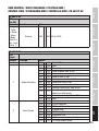
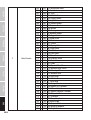
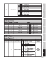
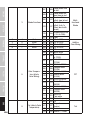
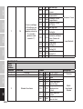
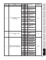
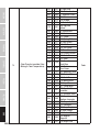
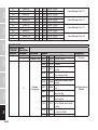
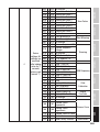
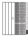
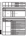
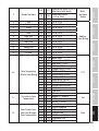
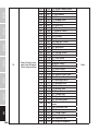
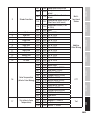
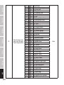
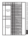
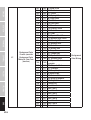
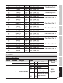
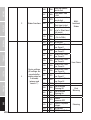
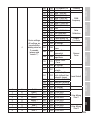
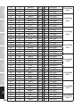
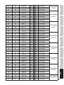
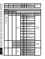
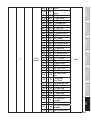
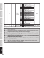
DMX
DMX CONTROL / DMX STEUERUNG / PILOTAGE DMX / 223
CONTROL DMX / STEROWANIE DMX / CONTROLLO DMX : PB 400 IP G2 223
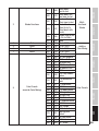
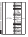
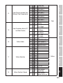
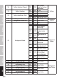
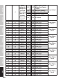
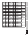
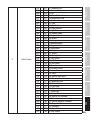
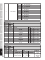
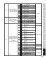
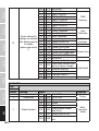
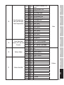
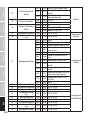
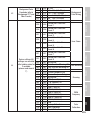
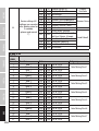
DMX CONTROL / DMX STEUERUNG / PILOTAGE DMX / 254
CONTROL DMX / STEROWANIE DMX / CONTROLLO DMX : PB 600 IP G2 254

6
DMX
ITALIANO
POLSKI
ESPAÑOL
FRANCAIS
DEUTSCHENGLISH
ENGLISH
You have made the right choice!
This device has been developed and manufactured to the highest quality standards to ensure
many years of problem-free operation. Please read this user manual carefully to be able to use
your new Cameo product quickly and optimally. Further information about Cameo Light is availab-
le on our website CAMEOLIGHT.COM.
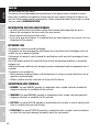
INFORMATION ON THIS USER MANUAL
• Carefully read the safety instructions and the entire manual before operating the device.
• Observe the warnings on the device and in the user manual.
• Always keep the user manual within reach.
• If you sell or pass on the device, it is important that you also include this user manual, as it is an
integral part of the product.
INTENDED USE
The product is a device for event technology!
This product has been developed for professional use in the field of event technology and is not
suitable for use as domestic lighting!
Furthermore, this product is only intended for qualified users with specialist knowledge of event
technology!
Use of the product outside the specified technical data and operating conditions is considered
improper use!
Liability for damage and third-party damage to persons and property due to inappropriate use is
excluded!
The product is not suitable for:
• Use by persons (including children) with limited physical, sensory or mental abilities or lack of
experience and knowledge.
• Children (children must be instructed not to play with the device).
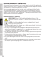
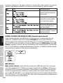
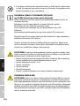
DEFINITIONS AND SYMBOLS
1. DANGER: The word DANGER, possibly in combination with a symbol, indicates immediately
dangerous situations or conditions for life and limb.
2. WARNING: The word WARNING, possibly in combination with a symbol, indicates potentially
dangerous situations or conditions for life and limb.
3. CAUTION: The word CAUTION, possibly in combination with a symbol, is used to indicate situa-
tions or conditions that may lead to injury.
4. ATTENTION: The word ATTENTION, possibly in combination with a symbol, refers to situations
or states that can lead to damage to property and/or the environment.

7
DMX DEUTSCHFRANCAIS
ESPAÑOL ENGLISH
ITALIANO POLSKI
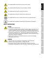
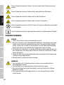
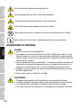
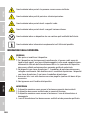
This symbol identifies hazards that can cause electric shock.
This symbol identifies hazardous areas or hazardous situations.
This symbol indicates hazards caused by hot surfaces.
This symbol indicates hazards caused by intense light sources.
This symbol indicates a device in which there are no user-replaceable parts.
This symbol indicates additional information on the operation of the product.
SAFETY INSTRUCTIONS
DANGER:
1. Do not open or modify the unit.
2. If your device no longer functions properly, if liquids or objects get inside it or if it
has been damaged in any other way, switch it off immediately and disconnect it
from the mains. The device may be repaired only by authorised repair technicians.
3. For devices of protection class 1, the protective conductor must be connected
correctly. Never disconnect the protective conductor. Devices of protection class 2
do not have a protective conductor.
4. Ensure that live cables are not kinked or otherwise mechanically damaged.
5. Never bypass the unit fuse.
WARNING:
1. The device may not be operated if it shows obvious signs of damage.
2. The device may only be installed in a voltage-free state.
3. If the power cable of the device is damaged, do not operate the device.
4. Permanently connected power cables may only be replaced by a qualified person.

8
DMX
ITALIANO
POLSKI
ESPAÑOL
FRANCAIS
DEUTSCHENGLISH
ATTENTION:
1. Do not operate the unit if it has been exposed to large temperature fluctuations
(for example, after transport). Moisture and condensation can damage the device.
Switch on the device only when it has reached room temperature.
2. Make sure that the voltage and frequency of the mains supply correspond to the
values indicated on the unit. If the device has a voltage selector switch, do not
connect the device until it has been set correctly. Use only suitable power cables.
3. To disconnect the unit from the mains at all poles, it is not sufficient to press the
on/off switch on the unit.
4. Make sure that the fuse used corresponds to the type printed on the unit.
5. Make sure that appropriate measures have been taken against overvoltage (e.g.
lightning strike).
6. Observe the specified maximum output current on units with Power Out connec-
tion. Ensure that the total current consumption of all connected devices does not
exceed the specified value.
7. Replace pluggable mains cables only with original cables.
DANGER:
1. Danger of suffocation! Plastic bags and small parts must be kept out of reach of
persons (including children) with reduced physical, sensory or mental capabilities.
2. Danger from falling down! Make sure that the device is securely installed and will
not fall down. Only use suitable stands or mounts (particularly for fixed installa-
tions). Ensure that accessories are properly installed and secured. Ensure that
applicable safety regulations are observed.
WARNING:
1. Use the device only in the manner intended.
2. Operate the device only with the accessories recommended and intended by the
manufacturer.
3. During installation, observe the safety regulations applicable in your country.
4. After connecting the unit, check all cable routes to avoid damage or accidents, e.g.
due to tripping hazards.
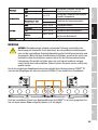
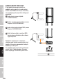
5. Always observe the specified minimum distance to normally flammable materials!
Unless explicitly stated, the minimum distance is 0.3 m.
6. Always observe the minimum distance to the illuminated surface that can be read
on the device!

9
DMX DEUTSCHFRANCAIS
ESPAÑOL ENGLISH
ITALIANO POLSKI
CAUTION:
1. In the case of moving components such as mounting brackets or other moving
components, there is a possibility of jamming.
2. In the case of units with motor-driven components, there is a risk of injury from the
movement of the unit. Sudden movement of the device can cause shock reactions.
3. The housing surface of the device can become very hot during regular operation.
Ensure that accidental touching of the housing is not possible. Always allow the
lamp to cool sufficiently before removal, maintenance work and charging etc.
ATTENTION:
1. Do not install or operate the device near any radiators, heat registers, stoves or other
heat sources. Ensure that the device is always installed in such a way that it is suffi-
ciently cooled and cannot overheat.
2. Do not place ignition sources such as burning candles near the device.
3. Ventilation openings must not be covered and fans must not be blocked.
4. Use the original packaging or packaging provided by the manufacturer for trans-
port.
5. Avoid shock or impact to the unit.
6. Observe the IP rating as well as the ambient conditions such as temperature and
humidity according to the specification.
7. Devices can be constantly further developed. In the event of deviating information on
operating conditions, performance or other device properties between the user manual
and the device labelling, the information on the device always takes priority.
8. The unit is not suitable for tropical climates and for operation above 2000 m above
sea level.
9. Unless explicitly stated, the unit is not suitable for operation in marine conditions .
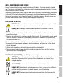
PLEASE NOTE:
For conversion or retrofit sets or accessories provided by the manufacturer, it is
essential to observe the instructions included.
CAUTION! IMPORTANT INFORMATION REGARDING LIGHTING PRODUCTS!
1. Never look directly into the beam of light, not even for a short period of time.
2. Never look into the beam of light using optical devices such as a magnifying glass.
3. Stroboscopic effects may cause epileptic seizures in susceptible individuals!
4. Permanently installed lamps are built into these lighting units. These may not
be replaced by the user. In the event of a fault, please contact your distribution
partner.

10
DMX
ITALIANO
POLSKI
ESPAÑOL
FRANCAIS
DEUTSCHENGLISH
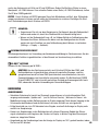
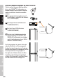
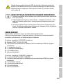
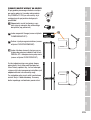
SIGNAL TRANSMISSION AND CONTROL BY RADIO (e.g. W-DMX or audio radio
systems, Bluetooth):
The quality and performance of wireless signal transmissions generally depends on
the ambient conditions.
The following factors can impact range and signal stability, for example:
Shielding (e.g. masonry, metal structures, water)
High volumes of radio traffic (e.g. powerful wireless LAN networks)
Interference
Electromagnetic radiation (e.g. LED video screens, dimmers)
All range specifications refer to free-field application with visual contact and without
interference!
The operation of transmission systems is subject to official regulations. These may
vary from region to region and must be checked by the operator before use (e.g. radio
frequency and transmission power).
WARNING: Devices with wireless signal transmission are not suitable for use in sen-
sitive areas in which radio operation can lead to potential detrimental effects. These
include e.g.:
• Hospitals, health centres or other healthcare facilities that provide patient treatment
with skilled personnel and equipment.
• Hazardous areas Class I, II and III
• Restricted areas
• Military facilities
• Aircraft or vehicles
• Areas where the use of mobile phones is prohibited
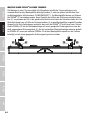
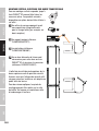
TRANSMISSION VIA W-DMX
WARNING: In general, wireless DMX transmission must not be used for applications
with safety-related factors that could result in personal injury or property damage in
the event of failure.
This applies in particular to moving scene or traverse structures, DMX-controlled mo-
tors/lifts or lifting devices for operating DMX-operated platform lifts, hydraulic systems
or comparable moving components.
Furthermore, wireless DMX transmission must not be used to trigger flame or pyro-
technic devices, explosion-driven effects, or to control gas or liquid effects. These
include e.g. CO2 cannons, confetti shooters, water effects or similar.

11
DMX DEUTSCHFRANCAIS
ESPAÑOL ENGLISH
ITALIANO POLSKI
NOTES ON PORTABLE OUTDOOR DEVICES
1. Temporary operation! Event equipment is generally only designed for temporary
operation.
2. Continuous operation or permanent structural installation – particularly outdoors –
can impair the function, surfaces and seals and accelerate material fatigue.
3. Damage to the surface coating can impair the device's corrosion protection.
Damaged surface coating (e.g. scratches) must be promptly repaired by suitable
measures.
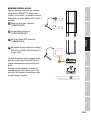
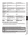
PACKAGING CONTENT
Remove the product from the packaging and remove all packaging material.
Please check the completeness and integrity of the delivery and notify your distribution partner
immediately after purchase if the delivery is not complete or if it is damaged.
Included with the CLPB400IPG2 product are:
X1 x PIXBAR® 400 IP65 G2 RGBW spotlights
X 2 sliding mounting feet with folding SPIN16® mounting spigot (pre-assembled)
X 1 x standard frost filter
X 1 x glare shield
X 1 x power cable
X User manual
Included with the CLPB600IPG2 product are:
X1 x PIXBAR® 600 IP65 G2 RGBWAUv spotlights
X2 sliding mounting feet with folding SPIN16® mounting spigot (pre-assembled)
X1 x standard frost filter
X1 x glare shield
X1 x power cable
XUser manual
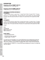
INTRODUCTION
PIXBAR® 400 IP G2 Outdoor Spotlights
CLPB400IPG2 with 16 4in1 RGBW LEDs
PIXBAR® 600 IP G2 Outdoor Spotlights
CLPB600IPG2 with 16 6in1 RGBWAUV LEDs

12
DMX
ITALIANO
POLSKI
ESPAÑOL
FRANCAIS
DEUTSCHENGLISH
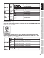
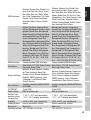
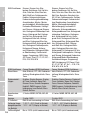
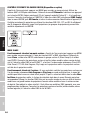
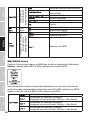
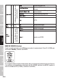
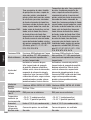
CONTROL FUNCTIONS:
CLPB400IPG2
1-channel, 3-channel Preset, 4-channel Direct, 7-channel Direct Control, 8-channel 16-bit,
10-channel Direct CCT, 11-channel Effect Pattern, 16-channel Wash, 36-channel Pattern,
48-channel Pixel RGB, 64-channel Pixel, 68-channel Pixel Dim, D2-channel, D4-channel Preset
and D7-channel Direct DMX Control
CLPB600IPG2
1-channel, 3-channel Preset, 6-channel Direct, 9-channel Direct Control, 12-channel 16-bit,
12-channel Direct CCT, 13-channel Effect Pattern, 20-channel Wash, 44-channel Pattern,
48-channel Pixel RGB, 96-channel Pixel, 100-channel Pixel Dim, D2-channel, D4-channel Preset
and D9-channel Direct DMX Control
RDM
W-DMX™
Master/Slave modes
Stand-alone functions
FEATURES:
• IP65 Rating
• Convection cooling
• Operating voltage: 100 - 240 VAC
The spotlights feature the RDM standard (remote device management). This remote device
management enables the status query and configuration of RDM end devices via an RDM-capable
controller, such as the optionally available Cameo UNICON (item number CLIREMOTE). The Cameo
UNICON also allows access to the entire spotlight menu.

13
DMX DEUTSCHFRANCAIS
ESPAÑOL ENGLISH
ITALIANO POLSKI
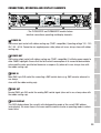
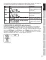
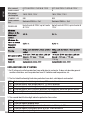
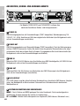
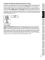
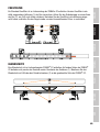
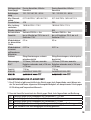
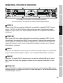
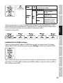
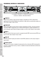
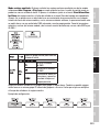
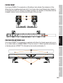
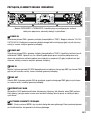
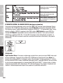
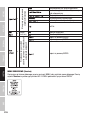
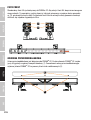
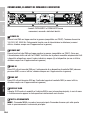
CONNECTIONS, OPERATING AND DISPLAY ELEMENTS
3
1 2
4
5
6
7 8
- The CLPB400IPG2 and CLPB600IPG2 models feature
identical connections, operating and display elements -
1 POWER IN
IP65 mains input socket with rubber sealing cap (TRUE1 compatible). Operating voltage 100 - 240
VAC / 50 - 60 Hz. Connection via supplied power cable (when not in use, always close with rubber
sealing cap).
2 POWER OUT
IP65 mains output socket with rubber sealing cap (TRUE1 compatible). Facilitates power supply to
other CAMEO spotlights. Ensure that the total current consumption of all connected devices does
not exceed the value specified on the device in amperes (A) (when not in use, always close with
the rubber sealing cap).
3 DMX IN
Male IP65 5-pin XLR socket for connecting a DMX control device (e.g. DMX console, when not in
use always
close with the rubber sealing cap).
4 DMX OUT
Female IP65 5-pin XLR socket for sending DMX control signal (when not in use, always close with
the rubber sealing cap).
5 OLED DISPLAY
The OLED display shows the currently activated operating mode or the current DMX address
(main display), the menu items in the menu and the numerical value or operating mode in certain
menu items.

14
DMX
ITALIANO
POLSKI
ESPAÑOL
FRANCAIS
DEUTSCHENGLISH
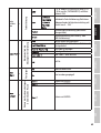
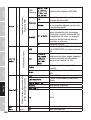
6 TOUCH-SENSITIVE CONTROLS
MENU- Press MENU to access the main menu. Press again or repeatedly to return to the main
display.
UP and DOWN – Select the menu items in the main menu (DMX address, operating mode, etc.)
and in the sub-menus using UP and DOWN. Change value or status in a menu item, e.g. DMX
address. To quickly change a value, such as the DMX start address, press and hold UP or DOWN.
ENTER – Press ENTER to access the menu level to make value or status changes, and to access
one of the sub-menus. Confirm value or status changes by pressing ENTER.
PLEASE NOTE:
• Before navigating the unit menu, make sure that the control panel is dry and clean
so that its functionality is not impaired.
• Water on the control unit can lead to incorrect operation of the spotlight, e.g. in
outdoor operation. Therefore, after configuring the spotlight, activate the lock
function to prevent incorrect operation by water (Settings -> Display -> Autolock).
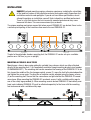
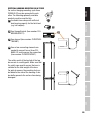
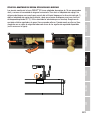
7 PRESSURE EQUALISATION ELEMENT
Pressure equalisation element to prevent condensation inside the housing. In order to ensure its
proper function, the element must be protected from contamination.
8 W-DMX™ ANTENNA
Antenna for control via W-DMX™.
ATTENTION: To ensure IP65 splash resistance for the DMX and network sockets, the
special input and output sockets must be correctly sealed with the IP65 special plugs
or the rubber sealing caps must be used for sealing. When connected correctly, or
when sealed correctly with the rubber sealing caps, the POWER IN and POWER OUT
sockets are protected from spraying water, as in accordance with IP65.
OPERATION
NOTE
• As soon as the spotlight is correctly connected to the power supply, the following are displayed
in succession: “Update wait ...” (for service purposes only), “Welcome to Cameo”, the model
name and the software version. After this process, the spotlight is ready for operation and the
previously activated operating mode is launched.
• If there is no input for approx. 30 seconds, the display automatically returns to the main dis-
play.

15
DMX DEUTSCHFRANCAIS
ESPAÑOL ENGLISH
ITALIANO POLSKI
• Note on the main display in the operating modes with external control: As soon as the control
signal is interrupted, the characters in the display start flashing; if the control signal is present
again, the flashing stops.
• Briefly pressing UP when in the main display rotates the display by 180°.
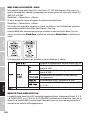
SETTING DMX START ADDRESS (DMX address)
Starting from the main display, press MENU to enter the main menu. Now use UP and DOWN to
select the menu item DMX Address and confirm with ENTER. Using the UP and DOWN buttons,
configure the desired DMX start address and press ENTER to confirm (highest value dependent
upon activated DMX mode).
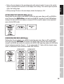
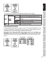
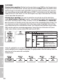
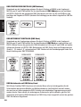
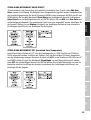
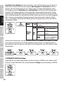
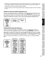
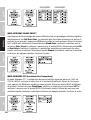
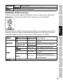
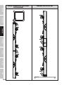
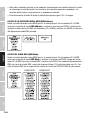
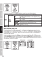
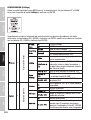
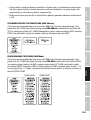
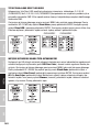
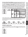
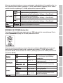
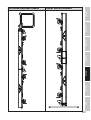
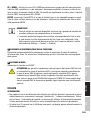
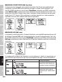
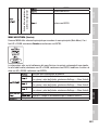
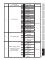
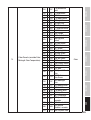
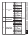
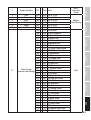
CONFIGURING DMX MODE (DMX Mode)
Starting from the main display, press MENU to enter the main menu. Now use UP and DOWN to
select the menu item DMX Mode and confirm with ENTER. Now select the desired DMX mode
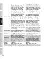
using UP and DOWN and confirm the selection with ENTER. DMX operating modes with DMX delay
channel and group selection (Group 0 - 24) are marked with "D". Tables with the channel assign-
ments can be found in these instructions under DMX CONTROL.
CLPB400IPG2 CLPB600IPG2

16
DMX
ITALIANO
POLSKI
ESPAÑOL
FRANCAIS
DEUTSCHENGLISH
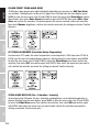
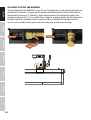
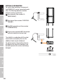
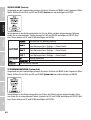
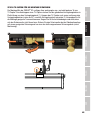
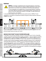
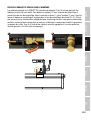
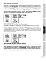
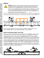
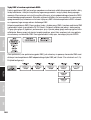
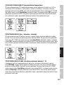
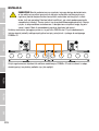
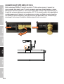
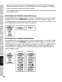
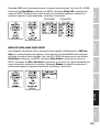
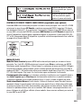
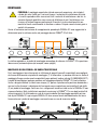
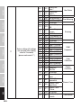
DMX modes with DMX delay channel
The DMX Delay function is a simple way to create a running light effect with a large number of
spotlights that are all the same model and that are all running the same software version. This
is otherwise only achievable with a suitable DMX controller and time-consuming programming.
All the spotlights used (same models, same software version) are set to the same DMX operating
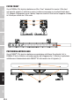
mode with DMX delay channel and controlled via the same DMX start address.
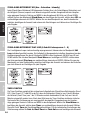
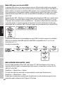
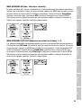
Setting the DMX delay: Select one of the DMX operating modes with DMX delay channel and
confirm the selection (in the example D4 CH Preset). Assign the spotlights to one of up to 24
groups (plus Group 0) according to preference, whereby several spotlights can be assigned to one
group. The group number is also the factor by which the set delay time set in the DMX controller
is multiplied. Confirm each entry by pressing ENTER.
The delay time (delay time of the DMX signal) is set by means of a DMX controller in the separate
DMX delay channel of the corresponding DMX mode (0.0s to 2.0s in 0.1s increments).
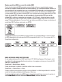
Setup example:
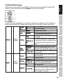
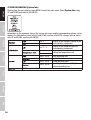
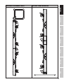
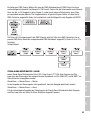
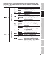
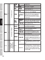
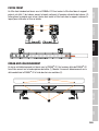
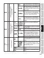
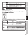
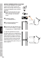
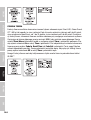
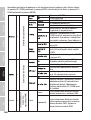
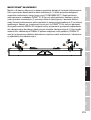
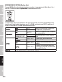
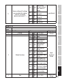
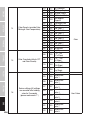
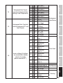
STAND-ALONE MENU MASTER / ALONE
In the stand-alone modes Direct LED, Color Preset, CCT, HSI, Auto Program and Play Loop, the
control signal of the corresponding mode can be output to slave units via XLR (DMX OUT) and
W-DMX™:
Stand Alone -> Master/Alone -> Master
If the output of the control signal is not desired, the output can be deactivated:
Stand Alone -> Master/Alone -> Alone
A delay for slave units can be set for the time-delayed output of the control signal of the
stand-alone modes Auto Program and Play Loop.
Starting from the main display, press MENU to enter the main menu. Now select the Stand Alone
menu item, confirm, select Master/Alone and confirm again.

17
DMX DEUTSCHFRANCAIS
ESPAÑOL ENGLISH
ITALIANO POLSKI
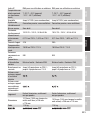
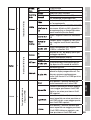
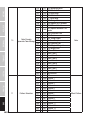
This will take you to the submenu for configuring the submenu items (see table).
Control signal is forwarded via DMX OUT
Activate DMX control signal forwarding via W-DMX
Deactivate sending of the DMX control signal via
W-DMX
Pairing with ready-to-pair W-DMX devices
Disconnect all W-DMX connections
Set DMX delay for slave units: Off, 0.1s - 2.0s
Do not forward control signal
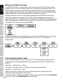
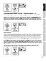
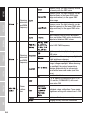
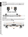
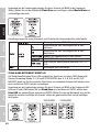
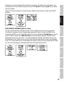
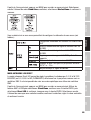
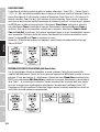
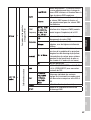
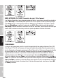
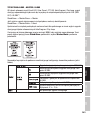
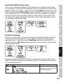
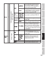
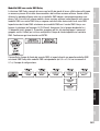
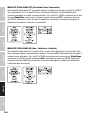
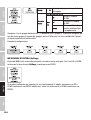
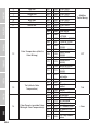
STAND-ALONE DIRECT LED MODE
The stand-alone Direct LED mode allows dimmer, strobe, R, G, B and W (CLPB400IPG2) or R, G, B,
W, A and UV (CLPB600IPG2) to be set directly on the unit, similar to a DMX controller. In this way,
an individual scene can be created without an additional DMX controller.
Starting from the main display, press MENU to enter the main menu. Use UP and DOWN to select
Stand Alone, confirm with ENTER, then select Direct LED and confirm again with ENTER. Now
select the menu item you want to edit, confirm the selection, set the desired value and confirm
the entry.
CLPB400IPG2 CLPB600IPG2

18
DMX
ITALIANO
POLSKI
ESPAÑOL
FRANCAIS
DEUTSCHENGLISH
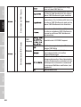
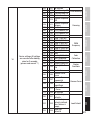
COLOUR PRESET STAND-ALONE MODE
49 different colour presets plus eight individually adjustable user presets (see Edit User Color)
are available. The brightness can be set at a higher level. Starting from the main display, press
MENU to enter the main menu. Use UP and DOWN to select the menu item Stand Alone, confirm
the selection, then select Color Preset and confirm again with ENTER. Now select GEL or User
Color and confirm the selection. The desired preset can now be selected, confirm the selection.
Now select Dimmer (brightness), confirm the selection and make the settings as desired. Confirm
the entry.
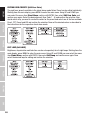
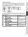
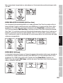
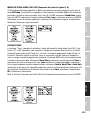
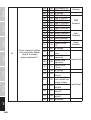
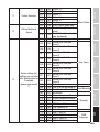
CCT STAND-ALONE MODE (Correlated Colour Temperature)
In stand-alone CCT mode, the colour temperature can be adjusted in 100K steps from 2200K to
8000K, plus the hue (tint) and brightness (dimmer). Starting from the main display, press MENU
to enter the main menu. Use UP and DOWN to select the Stand Alone menu item, confirm the
selection, then select CCT and confirm again with ENTER. Now select the menu item you want to
edit, confirm the selection and make the settings as desired. Confirm the entry.
STAND-ALONE MODE HSI (Hue - Saturation - Intensity)
In the stand-alone HSI mode, the hue, saturation and brightness can be adjusted separately as
desired. Starting from the main display, press MENU to enter the main menu. Use UP and DOWN
to select the Stand Alone menu item, confirm the selection, then select HSI and confirm again
with ENTER. Now select the menu item you want to edit, confirm the selection and make the
settings as desired. Confirm each entry.

19
DMX DEUTSCHFRANCAIS
ESPAÑOL ENGLISH
ITALIANO POLSKI
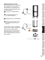
STAND-ALONE OPERATION MODE PLAY LOOP (8-step colour sequences 1 - 8)
The 8 available loops are pre-programmed at the factory, but can be customised in the Edit Loop
menu item. The brightness can be set at a higher level. Starting from the main display, press
MENU to enter the main menu. Using UP and DOWN, select the menu item Stand Alone, confirm
with ENTER, then select the submenu item Auto and confirm again with ENTER. Now select the
menu item you want to edit, confirm the selection and make the settings as desired. Confirm each
entry.
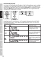
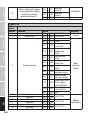
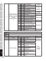
TIMER FUNCTION
The timer function allows timed control of the Direct LED, Colour Preset, CCT and HSI stand-alone
modes in such a way that the fade-in time (Fade In) can be set from 0 to 60 minutes, the dwell
time from 1 to 24 hours and the fade-out time from 0 to 60 minutes. After activation of the timer
function, the timer control will be implemented upon the next system start. Starting from the main
display, press MENU to enter the main menu. Select Stand Alone, confirm the selection, then
select Timer and confirm again. Select the setting On under Timer and confirm. For the individual
timer control settings, select Fade In, Dwell Time or Fade Out and confirm. You can now set the
respective value as desired. Confirm all entries. To deactivate the timer function, select the setting
Off under Timer and confirm the entry.
Note: The timer function is suitable for use in master/slave operation via cable and W-DMX™.

20
DMX
ITALIANO
POLSKI
ESPAÑOL
FRANCAIS
DEUTSCHENGLISH
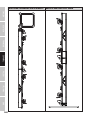
EDITING USER-PRESETS (Edit User Color)
The eight user presets available in the stand-alone mode Colour Preset can be edited individually.
Starting from the main display, press MENU to enter the main menu. Using UP and DOWN you
now select the menu item Stand Alone, confirm with ENTER, then select Edit User Color and
confirm once again. Select the desired preset (User Color 1 - 8) and confirm the selection. Now
decide which way you want to create the colour for the preset and select one of the four methods
Direct, CCT, Preset and HSI and confirm the selection. Now set the desired colour as described in
the instructions for the respective stand-alone mode.
EDIT LOOP (Edit LOOP)
Brightness, step duration and fade time can be set separately for all eight loops. Starting from the
main display, press MENU to enter the main menu. Using UP and DOWN you now select the menu
item Stand Alone, confirm with ENTER, then select Edit Loop and confirm once again. Now
select the desired loop for editing and confirm the selection.
La page est en cours de chargement...
La page est en cours de chargement...
La page est en cours de chargement...
La page est en cours de chargement...
La page est en cours de chargement...
La page est en cours de chargement...
La page est en cours de chargement...
La page est en cours de chargement...
La page est en cours de chargement...
La page est en cours de chargement...
La page est en cours de chargement...
La page est en cours de chargement...
La page est en cours de chargement...
La page est en cours de chargement...
La page est en cours de chargement...
La page est en cours de chargement...
La page est en cours de chargement...
La page est en cours de chargement...
La page est en cours de chargement...
La page est en cours de chargement...
La page est en cours de chargement...
La page est en cours de chargement...
La page est en cours de chargement...
La page est en cours de chargement...
La page est en cours de chargement...
La page est en cours de chargement...
La page est en cours de chargement...
La page est en cours de chargement...
La page est en cours de chargement...
La page est en cours de chargement...
La page est en cours de chargement...
La page est en cours de chargement...
La page est en cours de chargement...
La page est en cours de chargement...
La page est en cours de chargement...
La page est en cours de chargement...
La page est en cours de chargement...
La page est en cours de chargement...
La page est en cours de chargement...
La page est en cours de chargement...
La page est en cours de chargement...
La page est en cours de chargement...
La page est en cours de chargement...
La page est en cours de chargement...
La page est en cours de chargement...
La page est en cours de chargement...
La page est en cours de chargement...
La page est en cours de chargement...
La page est en cours de chargement...
La page est en cours de chargement...
La page est en cours de chargement...
La page est en cours de chargement...
La page est en cours de chargement...
La page est en cours de chargement...
La page est en cours de chargement...
La page est en cours de chargement...
La page est en cours de chargement...
La page est en cours de chargement...
La page est en cours de chargement...
La page est en cours de chargement...
La page est en cours de chargement...
La page est en cours de chargement...
La page est en cours de chargement...
La page est en cours de chargement...
La page est en cours de chargement...
La page est en cours de chargement...
La page est en cours de chargement...
La page est en cours de chargement...
La page est en cours de chargement...
La page est en cours de chargement...
La page est en cours de chargement...
La page est en cours de chargement...
La page est en cours de chargement...
La page est en cours de chargement...
La page est en cours de chargement...
La page est en cours de chargement...
La page est en cours de chargement...
La page est en cours de chargement...
La page est en cours de chargement...
La page est en cours de chargement...
La page est en cours de chargement...
La page est en cours de chargement...
La page est en cours de chargement...
La page est en cours de chargement...
La page est en cours de chargement...
La page est en cours de chargement...
La page est en cours de chargement...
La page est en cours de chargement...
La page est en cours de chargement...
La page est en cours de chargement...
La page est en cours de chargement...
La page est en cours de chargement...
La page est en cours de chargement...
La page est en cours de chargement...
La page est en cours de chargement...
La page est en cours de chargement...
La page est en cours de chargement...
La page est en cours de chargement...
La page est en cours de chargement...
La page est en cours de chargement...
La page est en cours de chargement...
La page est en cours de chargement...
La page est en cours de chargement...
La page est en cours de chargement...
La page est en cours de chargement...
La page est en cours de chargement...
La page est en cours de chargement...
La page est en cours de chargement...
La page est en cours de chargement...
La page est en cours de chargement...
La page est en cours de chargement...
La page est en cours de chargement...
La page est en cours de chargement...
La page est en cours de chargement...
La page est en cours de chargement...
La page est en cours de chargement...
La page est en cours de chargement...
La page est en cours de chargement...
La page est en cours de chargement...
La page est en cours de chargement...
La page est en cours de chargement...
La page est en cours de chargement...
La page est en cours de chargement...
La page est en cours de chargement...
La page est en cours de chargement...
La page est en cours de chargement...
La page est en cours de chargement...
La page est en cours de chargement...
La page est en cours de chargement...
La page est en cours de chargement...
La page est en cours de chargement...
La page est en cours de chargement...
La page est en cours de chargement...
La page est en cours de chargement...
La page est en cours de chargement...
La page est en cours de chargement...
La page est en cours de chargement...
La page est en cours de chargement...
La page est en cours de chargement...
La page est en cours de chargement...
La page est en cours de chargement...
La page est en cours de chargement...
La page est en cours de chargement...
La page est en cours de chargement...
La page est en cours de chargement...
La page est en cours de chargement...
La page est en cours de chargement...
La page est en cours de chargement...
La page est en cours de chargement...
La page est en cours de chargement...
La page est en cours de chargement...
La page est en cours de chargement...
La page est en cours de chargement...
La page est en cours de chargement...
La page est en cours de chargement...
La page est en cours de chargement...
La page est en cours de chargement...
La page est en cours de chargement...
La page est en cours de chargement...
La page est en cours de chargement...
La page est en cours de chargement...
La page est en cours de chargement...
La page est en cours de chargement...
La page est en cours de chargement...
La page est en cours de chargement...
La page est en cours de chargement...
La page est en cours de chargement...
La page est en cours de chargement...
La page est en cours de chargement...
La page est en cours de chargement...
La page est en cours de chargement...
La page est en cours de chargement...
La page est en cours de chargement...
La page est en cours de chargement...
La page est en cours de chargement...
La page est en cours de chargement...
La page est en cours de chargement...
La page est en cours de chargement...
La page est en cours de chargement...
La page est en cours de chargement...
La page est en cours de chargement...
La page est en cours de chargement...
La page est en cours de chargement...
La page est en cours de chargement...
La page est en cours de chargement...
La page est en cours de chargement...
La page est en cours de chargement...
La page est en cours de chargement...
La page est en cours de chargement...
La page est en cours de chargement...
La page est en cours de chargement...
La page est en cours de chargement...
La page est en cours de chargement...
La page est en cours de chargement...
La page est en cours de chargement...
La page est en cours de chargement...
La page est en cours de chargement...
La page est en cours de chargement...
La page est en cours de chargement...
La page est en cours de chargement...
La page est en cours de chargement...
La page est en cours de chargement...
La page est en cours de chargement...
La page est en cours de chargement...
La page est en cours de chargement...
La page est en cours de chargement...
La page est en cours de chargement...
La page est en cours de chargement...
La page est en cours de chargement...
La page est en cours de chargement...
La page est en cours de chargement...
La page est en cours de chargement...
La page est en cours de chargement...
La page est en cours de chargement...
La page est en cours de chargement...
La page est en cours de chargement...
La page est en cours de chargement...
La page est en cours de chargement...
La page est en cours de chargement...
La page est en cours de chargement...
La page est en cours de chargement...
La page est en cours de chargement...
La page est en cours de chargement...
La page est en cours de chargement...
La page est en cours de chargement...
La page est en cours de chargement...
La page est en cours de chargement...
La page est en cours de chargement...
La page est en cours de chargement...
La page est en cours de chargement...
La page est en cours de chargement...
La page est en cours de chargement...
La page est en cours de chargement...
La page est en cours de chargement...
La page est en cours de chargement...
La page est en cours de chargement...
La page est en cours de chargement...
La page est en cours de chargement...
La page est en cours de chargement...
La page est en cours de chargement...
La page est en cours de chargement...
La page est en cours de chargement...
La page est en cours de chargement...
La page est en cours de chargement...
La page est en cours de chargement...
La page est en cours de chargement...
La page est en cours de chargement...
La page est en cours de chargement...
La page est en cours de chargement...
La page est en cours de chargement...
La page est en cours de chargement...
La page est en cours de chargement...
La page est en cours de chargement...
La page est en cours de chargement...
La page est en cours de chargement...
La page est en cours de chargement...
La page est en cours de chargement...
La page est en cours de chargement...
La page est en cours de chargement...
La page est en cours de chargement...
La page est en cours de chargement...
La page est en cours de chargement...
La page est en cours de chargement...
La page est en cours de chargement...
La page est en cours de chargement...
La page est en cours de chargement...
La page est en cours de chargement...
La page est en cours de chargement...
-
 1
1
-
 2
2
-
 3
3
-
 4
4
-
 5
5
-
 6
6
-
 7
7
-
 8
8
-
 9
9
-
 10
10
-
 11
11
-
 12
12
-
 13
13
-
 14
14
-
 15
15
-
 16
16
-
 17
17
-
 18
18
-
 19
19
-
 20
20
-
 21
21
-
 22
22
-
 23
23
-
 24
24
-
 25
25
-
 26
26
-
 27
27
-
 28
28
-
 29
29
-
 30
30
-
 31
31
-
 32
32
-
 33
33
-
 34
34
-
 35
35
-
 36
36
-
 37
37
-
 38
38
-
 39
39
-
 40
40
-
 41
41
-
 42
42
-
 43
43
-
 44
44
-
 45
45
-
 46
46
-
 47
47
-
 48
48
-
 49
49
-
 50
50
-
 51
51
-
 52
52
-
 53
53
-
 54
54
-
 55
55
-
 56
56
-
 57
57
-
 58
58
-
 59
59
-
 60
60
-
 61
61
-
 62
62
-
 63
63
-
 64
64
-
 65
65
-
 66
66
-
 67
67
-
 68
68
-
 69
69
-
 70
70
-
 71
71
-
 72
72
-
 73
73
-
 74
74
-
 75
75
-
 76
76
-
 77
77
-
 78
78
-
 79
79
-
 80
80
-
 81
81
-
 82
82
-
 83
83
-
 84
84
-
 85
85
-
 86
86
-
 87
87
-
 88
88
-
 89
89
-
 90
90
-
 91
91
-
 92
92
-
 93
93
-
 94
94
-
 95
95
-
 96
96
-
 97
97
-
 98
98
-
 99
99
-
 100
100
-
 101
101
-
 102
102
-
 103
103
-
 104
104
-
 105
105
-
 106
106
-
 107
107
-
 108
108
-
 109
109
-
 110
110
-
 111
111
-
 112
112
-
 113
113
-
 114
114
-
 115
115
-
 116
116
-
 117
117
-
 118
118
-
 119
119
-
 120
120
-
 121
121
-
 122
122
-
 123
123
-
 124
124
-
 125
125
-
 126
126
-
 127
127
-
 128
128
-
 129
129
-
 130
130
-
 131
131
-
 132
132
-
 133
133
-
 134
134
-
 135
135
-
 136
136
-
 137
137
-
 138
138
-
 139
139
-
 140
140
-
 141
141
-
 142
142
-
 143
143
-
 144
144
-
 145
145
-
 146
146
-
 147
147
-
 148
148
-
 149
149
-
 150
150
-
 151
151
-
 152
152
-
 153
153
-
 154
154
-
 155
155
-
 156
156
-
 157
157
-
 158
158
-
 159
159
-
 160
160
-
 161
161
-
 162
162
-
 163
163
-
 164
164
-
 165
165
-
 166
166
-
 167
167
-
 168
168
-
 169
169
-
 170
170
-
 171
171
-
 172
172
-
 173
173
-
 174
174
-
 175
175
-
 176
176
-
 177
177
-
 178
178
-
 179
179
-
 180
180
-
 181
181
-
 182
182
-
 183
183
-
 184
184
-
 185
185
-
 186
186
-
 187
187
-
 188
188
-
 189
189
-
 190
190
-
 191
191
-
 192
192
-
 193
193
-
 194
194
-
 195
195
-
 196
196
-
 197
197
-
 198
198
-
 199
199
-
 200
200
-
 201
201
-
 202
202
-
 203
203
-
 204
204
-
 205
205
-
 206
206
-
 207
207
-
 208
208
-
 209
209
-
 210
210
-
 211
211
-
 212
212
-
 213
213
-
 214
214
-
 215
215
-
 216
216
-
 217
217
-
 218
218
-
 219
219
-
 220
220
-
 221
221
-
 222
222
-
 223
223
-
 224
224
-
 225
225
-
 226
226
-
 227
227
-
 228
228
-
 229
229
-
 230
230
-
 231
231
-
 232
232
-
 233
233
-
 234
234
-
 235
235
-
 236
236
-
 237
237
-
 238
238
-
 239
239
-
 240
240
-
 241
241
-
 242
242
-
 243
243
-
 244
244
-
 245
245
-
 246
246
-
 247
247
-
 248
248
-
 249
249
-
 250
250
-
 251
251
-
 252
252
-
 253
253
-
 254
254
-
 255
255
-
 256
256
-
 257
257
-
 258
258
-
 259
259
-
 260
260
-
 261
261
-
 262
262
-
 263
263
-
 264
264
-
 265
265
-
 266
266
-
 267
267
-
 268
268
-
 269
269
-
 270
270
-
 271
271
-
 272
272
-
 273
273
-
 274
274
-
 275
275
-
 276
276
-
 277
277
-
 278
278
-
 279
279
-
 280
280
-
 281
281
-
 282
282
-
 283
283
-
 284
284
-
 285
285
-
 286
286
-
 287
287
-
 288
288


Cameo PIXBAR® 600 IP G2 Manuel utilisateur
- Catégorie
- Projecteurs
- Taper
- Manuel utilisateur
dans d''autres langues
Documents connexes
-
Cameo PIXBAR® TW IP G2 Manuel utilisateur
-
-
-
-
-
-
-
Cameo F2 FC IP Manuel utilisateur
-
-
Autres documents
-
Nicols PAR LED 1210 Z Le manuel du propriétaire
-
EDENWOOD 972157 Manuel utilisateur
-
Orion ORCAN4 Le manuel du propriétaire
-
Orion ORFX107 Le manuel du propriétaire
-
 Robert Juliat SULLY 315L 4C Guide de démarrage rapide
-
AEG 191215 Alfie LED Ceiling Spotlight Manuel utilisateur
-
Sentiotec Pro-DMX Manuel utilisateur
-
AEG 191213 LED Wall Spot Metal-Plastic Dimmable Mode d'emploi
-
Tridonic PWM CV 4CH Guide d'installation
-
Pablo Carousel Manuel utilisateur
