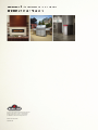
NAPOLEON ALLURAVISION Series Manuel utilisateur
- Taper
- Manuel utilisateur

FRENCH
PG.35
W415-2212 / G / 02.10.20
ADD MANUAL TITLE
Wolf Steel Ltd., 24 Napoleon Rd., Barrie, ON, L4M 0G8 Canada / 103 Miller Drive, Crittenden, Kentucky, USA, 41030
Phone 1 (866) 820-8686 • www.napoleon.com • [email protected]
CERTIFIED TO THE CANADIAN AND AMERICAN NATIONAL STANDARDS:
CSA 22.2 NO. 46 / UL 1278
INSTALLER:
Leave this manual with the appliance
CONSUMER:
Retain this manual for future reference
Product Name / Code
(MUST use title from Price Book)
(IF MULTIPLE, _____ ILLUSTRATED)
MULTIPLE PRODUCT CODES (LEAVE BLANK IF N/A)
ADD PRODUCT IMAGE
ADD BUTTON BATTERY WARNING IF APPLICABLE
CSA /
INTERTEK
LOGO
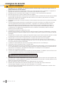
SAFETY INFORMATION
- Do not store or use gasoline or other
fl ammable vapors and liquids in the vicinity of
this or any other appliance.
FIRE OR EXPLOSION HAZARD
If the information in these instructions are
not followed exactly, a fi re or explosion may
result causing property damage, personal
injury, or loss of life.
WARNING
!
ENGLISH
$10.00
FOR INDOOR USE ONLY
IF INSTALLATION + OPERATION, ADD SERIAL
NUMBER LABEL HERE
IF SEPARATE MANUALS, ADD “PLACE
BARCODE LABEL ON THE OWNER’S MANUAL”
Alluravision™ Series
FRENCH PG. 35
NEFL42CHD / NEFL50CHD / NEFL60CHD / NEFL74CHD / NEFL100CHD
NEFL42CHS / NEFL50CHS / NEFL60CHS / NEFL74CHS
INSTALLATION AND
OPERATION MANUAL
2021
This appliance has a remote that requires button
batteries that are hazardous to young children.
(NEFL50CHD llustrated)

W415-2212 / G / 02.10.20
EN
2
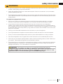
safety information
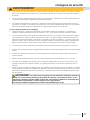
• If equipped with a heater, this appliance can be hot when operated and can cause severe
burns if contacted.
• Do not operate appliance before reading and understanding operating instructions. Failure to operate
appliance according to operating instructions could cause fi re or injury.
• Do not install damaged, incomplete or substitute components.
• Do not burn wood or other materials in this appliance.
• All electric appliances have hot and arcing or sparking parts inside. Do not use it in areas where a gas
line, paint or fl ammable liquids are present.
• Any safety screen or guard removed for servicing must be replaced prior to operating the appliance.
• It is imperative that the control compartments, circulating blower and its passageway in the appliance
are kept clean. The appliance should be inspected before use and at least annually by a qualifi ed service
person. More frequent cleaning may be required due to excessive lint from carpeting, bedding material,
etc. The appliance area must be kept clear and free from combustible materials, gasoline and other
fl ammable vapors and liquids.
• Under no circumstances should this appliance be modifi ed.
• Do not use this appliance if any part has been under water. Immediately call a qualifi ed service technician to
inspect the appliance and to replace any part of the control system which has been under water.
• If equipped with a glass door, do not operate the appliance with the glass door removed, cracked or
broken. Replacement of the glass should be done by a licensed or qualifi ed service person. Do not strike
or slam shut the appliance glass door.
• Keep the packaging material out of reach of children and dispose of the material in a safe manner. As
with all plastic bags, these are not toys and should be kept away from children and infants.
• Servicing should be done only while the appliance is disconnected from the power supply circuit.
• Always unplug appliance when not in use.
• Do not operate this appliance with a damaged cord or plug after the appliance malfunctions, has been
dropped or damaged in any manner. Return appliance to authorized service facility for examination,
electrical or mechanical adjustment, or repair.
• Do not use outdoors.
• When installing this appliance in a room where water is present, the installation must comply with codes
recognizing the increased hazard of electrical shock and electrocution.
• Do not run cord under carpeting. Do not cover cord with throw rugs, runners, or the like. Arrange cord
away from traffi c area and where it will not be tripped over.
• Connect to properly grounded outlets only.
• Do not insert or allow foreign objects to enter any ventilation or exhaust opening as this may cause an
electric shock or fi re, or damage the appliance.
• It is normal for your electric appliance to produce noise, especially when installed in a quiet space such
as a bedroom.
!
WARNING
Insert appropriate “Bathroom Warning (Electric)” (see 3-Warnings template folder).
note:
This appliance is NOT suitable for installation in a bathroom.

EN
W415-2212 / G / 02.10.20
3
safety information
• To prevent a possible fi re, do not block air intakes or exhaust in any manner. Do not use on soft surfaces, like
a carpet, where openings may become blocked.
• Always plug appliances directly into a wall outlet/receptacle. Never use an extension cord or relocatable
power tap (outlet/power strip).
• These appliances are tested and listed for use only with the optional accessories listed in these instructions.
Use of optional accessories not specifi cally tested for this appliance could void the warranty and/or result in
a safety hazard.
For appliances equipped with a heater:
• Risk of burns. Power to the appliance should be turned off and the appliance allowed to cool before
servicing. To disconnect power to the appliance, turn controls to off, then remove plug from outlet.
• Young children should be carefully supervised when they are in the same room as the appliance.
Toddlers, young children and others may be susceptible to accidental contact burns. A physical barrier is
recommended if there are at risk individuals in the house. To restrict access to an appliance or stove, install
an adjustable safety gate to keep toddlers, young children and other at risk individuals out of the room and
away from hot surfaces.
• Clothing or other fl ammable material should not be placed on or near the appliance.
• Due to high temperatures, the appliance should be located out of traffi c and away from furniture and draperies.
• Ensure you have incorporated adequate safety measure to protect infants/toddlers from touching hot surfaces.
• Even after the appliance is off, the glass and/or screen will remain hot for an extended period of time.
• Check with your local hearth specialty dealer for safety screens and hearth guards to protect children from
hot surfaces. These screens and guards must be fastened to the fl oor.
• Ensure clearances to combustibles are maintained when building a mantel or shelves above the appliance.
Elevated temperatures on the wall or in the air above the appliance can cause melting, discolouration or
damage to decorations, a TV or other electronic components.
!
WARNING
!
WARNING:
This product can expose you to chemicals including lead and lead
compounds, which are known to the State of California to cause cancer, and chemicals includ-
ing BBP and DEHP, which are known to the State of California to cause birth defects or other
reproductive harm. For more information, go to www.P65Warnings.ca.gov.

W415-2212 / G / 02.10.20
EN
4
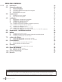
table of contents
1.0 dimensions 5
2.0 general information 6
2.1 listing approvals 6
2.2 general instructions 6
2.3 rating plate information 7
2.4 hardware list 7
2.5 label location 8
3.0 location 9
3.1 unpacking and testing the appliance 9
3.2 grounding the appliance 9
4.0 installation 10
4.1 minimum clearance to combustibles 10
4.2 minimum mantel clearances 10
4.3 installing the appliance onto the wall 11
4.4 recessing the appliance into the wall 13
4.4.1 trim installation (recessed installation only) 14
4.4.2 installing the appliance into a mantel 15
4.5 120V hard wiring installation 16
4.5.1 NEFL42 / 50 / 60 / 74 CHS 120V hardwiring 16
4.5.2 NEFL42 / 50 / 60 / 74 CHD 120V hardwiring 17
4.6 240V hard wiring installation (NEFL42 / 50 / 60 / 74 / 100 CHD only) 18
5.0 framing - recessed installation 20
6.0 finishing 21
6.1 crystal ember installation 21
6.2 optional topaz glass chips and drift wood log installation 21
6.3 front glass installation and removal 22
7.0 wiring diagram 23
7.1 NEFL42 / 50 / 60 / 74 CHS wiring diagram 23
7.2 NEFL42 / 50 / 60 / 74 / 100 CHD wiring diagram 24
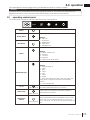
8.0 operation 25
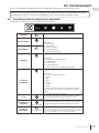
8.1 operating control panel 25
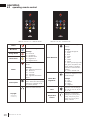
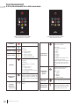
8.2 operating remote control 26
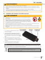
9.0 maintenance 27
9.1 remote battery installation 27
10.0 replacement parts 28
10.1 NEFL42 / 50 / 60 / 74 CHS 29
10.2 NEFL42 / 50 / 60 / 74 / 100 CHD 30
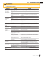
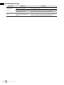
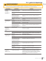
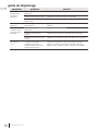
11.0 troubleshooting 31
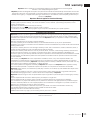
12.0 warranty 33
The information throughout this manual is believed to be correct at the time of printing. Wolf Steel Ltd. reserves
the right to change or modify any information within this manual at any time without notice. Changes, other than
editorial, are denoted by a vertical line in the margin.
note:

EN
W415-2212 / G / 02.10.20
5
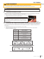
dimensions
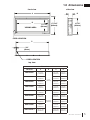
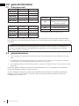
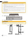
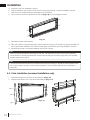
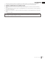
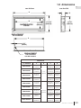
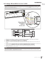
1.0 dimensions
A
17 5/16”
(440mm)
D
VIEWING AREA
CORD LOCATION
11 1/16”
(281mm)
Dimensions
Model No. A B C D
NEFL42CHS-1
44 7/16”
(1128mm)
4 1/4”
(108mm)
42 1/16”
(1068mm)
40 1/4”
(1022mm)
NEFL50CHS-1
52 11/16”
(1338mm)
50 5/16”
(1278mm)
48 1/2”
(1232mm)
NEFL60CHS-1
62 9/16”
(1588mm)
60 3/16”
(1528mm)
58 5/16”
(1482mm)
NEFL74CHS-1
76 3/4”
(1948mm)
74 5/16”
(1888mm)
72 1/2”
(1842mm)
NEFL42CHD-1
44 7/16”
(1128mm)
5 13/16”
(148mm)
42 1/16”
(1068mm)
40 1/4”
(1022mm)
NEFL50CHD-1
52 11/16”
(1338mm)
50 5/16”
(1278mm)
48 1/2”
(1232mm)
NEFL60CHD-1
62 9/16”
(1588mm)
60 3/16”
(1528mm)
58 5/16”
(1482mm)
NEFL74CHD-1
76 3/4”
(1948mm)
74 5/16”
(1888mm)
72 1/2”
(1842mm)
NEFL100CHD-1
102 11/16”
(2608mm)
100 5/16”
(2548mm)
98 1/2”
(2502mm)
B
15 7/8”
(402mm)
front view side view
top view
C
CORD LOCATION
3/4”
(18mm)

W415-2212 / G / 02.10.20
EN
6
general information
2.0 general information
This appliance has been tested in accordance with the CSA Standards for fi xed and location-dedicated electric
room appliances in the United States and Canada. If you need assistance during installation, please contact your
local dealer.
*Not applicable to NEFL42CHS-74CHS
note:
This appliance must be electrically wired and grounded in accordance with local codes or, in the absence of
local codes, with National Electric Code ANSI/NFPA 70-latest edition in the United States or the Canadian
Electric Code, CSA C22.1 in Canada.
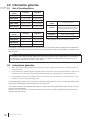
2.1 listing approvals
2.2 general instructions
• Prior to plugging your appliance into an electrical outlet, verify that the house circuit breakers for the outlet
are on.
• The appliance may emit a slight, harmless odour when fi rst used. This odour is normal and it is caused by
the initial heating of internal appliance elements and will not occur again.
• If your appliance does not emit heat when called for, consult the “operation” section of this manual for further
information.
• Use with a CSA or UL certifi ed surge protector.
• Do not route the power cord directly underneath the appliance.
This electric appliance meets the construction and safety standards of H.U.D. for application in manufactured
Model No. Net Weight Gross Weight
NEFL42CHD
63.3 lbs (28.7kg) 82.7 lbs (37.5kg)
NEFL50CHD
71.7 lbs (32.5kg) 94.8 lbs (43kg)
NEFL60CHD
82.7 lbs (37.5kg) 109.1 lbs (49.5kg)
NEFL74CHD
99.6 lbs (45.2kg) 130 lbs (59kg)
NEFL100CHD
130 lbs (59kg) 167.6 lbs (76kg)
Model No. Net Weight Gross Weight
NEFL42CHS
46.7 lbs (21.2kg) 62.4 lbs (28.3kg)
NEFL50CHS
54.5 lbs (24.7kg) 73 lbs (33.1kg)
NEFL60CHS
63.3 lbs (28.7kg) 84.2 lbs (38.2kg)
NEFL74CHS
77.2 lbs (35kg) 103.6 lbs (47kg)
Description
Electric Appliance
Type
3 Way Mounting Unit
Wall-Mount, Recess into Wall and
Assemble with mantel
Voltage
120V AC / 240V AC*
Watts
MAX 1450W / 2800W*
Amps
15 AMP Grounded Circuit
This electric appliance meets the contruction and safety standards of H.U.D. for application in manufactured
homes when installed according to these instructions.
As with most electronic devices, your new electric appliance has been designed to operate at temperatures
between 5°C (41°F) and 35°C (95°F). During the colder winter months, allow the appliance to reach room
temperature before turning it on.

EN
W415-2212 / G / 02.10.20
7
general information
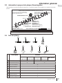
The below illustration is for reference only. Refer to the appliance rating plate for accurate information.
The rating plate must remain with the appliance at all times. It must not be removed.
note:
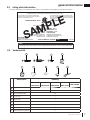
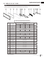
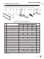
2.4 hardware list
2.3 rating plate information
Description Quantity
NEFL42CHS
/ NEFL42CHD
NEFL50CHS
/ NEFL50CHD
NEFL60CHS
/ NEFL60CHD
NEFL74CHS
/ NEFL74CHD
NEFL100CHD
A
Wood Screws 8 14
B
Drywall Anchors 8 14
C
ST4x12 Metal Screws 25
D
Cover Plate 1
E
Strain Relief 1
F
Cord Corner 2
G
Cord Cover 2
H
Door Cover Plate 1
I
Side Wall Mounting Bracket 2
W385-2226
CERTIFIED UNDER CANADIAN AND AMERICAN NATIONAL STANDARD: CSA 22.2 NO. 46 AND UL 2021 / HOMOLOGUÉ SELON LES
NORMES NATIONALES CANADIENNES ET AMÉRICAINES: CSA 22.2 NO. 46 UL 2021
FOYER ÉLECTRIQUE. HOMOLOGUÉ POUR INSTALLATION
DANS UNE CHAMBRE À COUCHER, UNE SALLE DE BAIN ET
UN STUDIO. APPROPRIÉ POUR INSTALLATION DANS UNE
MAISON MOBILE.
ELECTRIC FIREPLACE. SUITABLE FOR BEDROOM
AND BED-SITTING ROOM INSTALLATION. SUITABLE
FOR MOBILE HOME INSTALLATION.
VOLTAGE: 120VAC TENSION: 120VCA
FREQUENCY: 60Hz FRÉQUENCE: 60Hz
POWER: 1450W PUISSANCE: 1450W
DATE CODE: XXXXX CODE DE DATE:
DESIGNED IN NORTH AMERICA
BY WOLF STEEL LTD.
MADE IN CHINA FABRIQUÉ EN CHINE
WOLF STEEL LTD.
24 NAPOLEON ROAD,
BARRIE, ON, L4M 0G8 CANADA
SERIAL NUMBER/NO. DE SÉRIE:
NEFL
MODEL / MODÈLE
DÉSIGNÉ EN AMÉRIQUE DE
NORD PAR WOLF STEEL LTD.
MASTER CONTRACT: 161746
CONTRAT-CADRE: 161746
NEFL42CHS
NEFL42CHS
SAMPLE
E
F
G
H
D
A
C
B
I

W415-2212 / G / 02.10.20
EN
8
general information
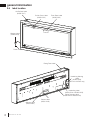
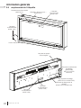
2.5 label location
Do Not Cover Label
(W385-2210)
Warning Label
(W385-1944)
Caution Label
(W385-1945)
Wiring Diagram Label
(W385-2222 or W385-2223)
Hardwiring Label
(W385-2224 or W385-2225)
Rating Plate Label
Warning Label
(W385-1943)
Power Cord
Hot Surface Label
(W385-2017)
Front Glass Label
(W385-2321)
Hardwiring Warning
Label
(W385-2380)
(NEFL42-100CHD only)

EN
W415-2212 / G / 02.10.20
9
locating appliance
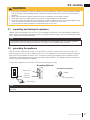
3.1 unpacking and testing the appliance
3.2 grounding the appliance
• Due to high temperatures, this electric appliance should be located out of traffi c. Keep combustible materials
such as furniture, pillows, bedding, papers, clothes and curtains at least 36” (91.4cm) from the front of the
appliance.
• Never locate this electric appliance where it may fall into a bathtub or other water container.
• Wear safety gloves and safety glasses for protection during installation and maintenance.
• To prevent contact with sagging or loose insulation, the electric appliance must not be installed against vapor
barrier or exposed insulation. Localized overheating could occur and a fi re could result.
• Do not expose the electric appliance to the elements (such as rain, etc.).
!
WARNING
Carefully remove the appliance from the box. Prior to installing the appliance, remove all packaging material and
test to make sure the appliance operates properly by plugging the power supply cord into a conveniently located
120V, 15 Amp minimum grounded outlet.
Grounding Methods
Metal Screw
(A)
Not allowed in Canada
Grounding Means
Adapter
Grounding Pin
Cover of
grounded
outlet box
(C)
(B)
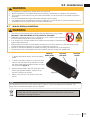
The appliance is shipped with the front glass not assembled onto the appliance (see “front glass installation
and removal” section for assembly instructions). Front glass must be installed during operation.
note:
3.0 location
This appliance must be connected to a dedicated 15 amp circuit. The use of an extension cord is NOT
permitted.
note:
NEFL42-74CHS models are for use with 120 volts; NEFL42-100CHD models are for use with 240 volts. The
cord has a plug as shown in (A). An adapter as shown in (C) is available for conecting three-blade grounding type
plugs to two-slot receptables, as shown in (B). The green grounding plug extending from the adapter must be
connected to a permanent ground such as a properly grounded outlet box. The adapter should not be used if a
three-slow grounded receptable is available.
To disconnect appliance, turn controls to OFF, then remove plug from outlet.

W415-2212 / G / 02.10.20
EN
10
installation
4.0 installation
!
WARNING
• Risk of fi re! The power cord must not be pinched against a sharp edge. Secure cord to avoid tripping or
snagging to reduce the risk of fi re, electric shock, or personal injury. Do not run cord under carpeting. Do not
cover cord with throw rugs, runners, or similar items. Arrange cord away from traffi c areas and where it will not
be tripped over.
• Risk of fi re! To prevent a possible fi re, do not block air intake or exhaust in any manner. Do not use on soft
surfaces where openings may become blocked.
• Risk of fi re! Do not blow or place insulation against the appliance.
• This electric appliance is tested and listed for use only with the approved optional accessories. Use of optional
accessories not specifi cally tested for this electric appliance could void the warranty and/or result in a safety
hazard.
• If the information in these instructions is not followed exactly, a fi re or explosion may result causing property
damage, personal injury, or death. Do not store or use gasoline or other fl ammable vapors in the vicinity of this
or any other appliance.
• This appliance is heavy. It is highly recommended that two people install this appliance.
• If your appliance is equipped with a heater, ensure the heater vents cannot, in any way, be covered as it may
create a fi re hazard.
• Do not run the power cord horizontally, directly below the appliance.
Follow all national and local electrical codes.
note:
Your appliance is a wall-mounted, recessed and/or mantel installed appliance. Select a suitable location that is not
susceptible to moisture and is away from drapes, furniture and high traffi c areas.
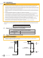
4.1 minimum clearance to combustibles
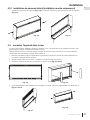
4.2 minimum mantel clearances
• When using paint or lacquer to fi nish the mantel, the paint or lacquer must be heat resistant to prevent
discolouration.
!
WARNING
Side View
(
Wall Mount
)
8" (203mm)
Mantel
Floor
Wall
Side View (recessed into a wall)
8" (203mm)
0"
0"
0
Mantel
Floor
Measurements are taken from the top of the appliance:
Bottom, Sides, and Back
0”
Top
0” recessed into wall and 8” (203mm) to mantel

EN
W415-2212 / G / 02.10.20
11
installation
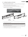
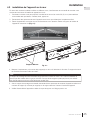
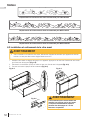
4.3 installing the appliance onto the wall
Due to the many different materials used on different walls, it is highly recommended that you consult your local
builder before you install this appliance on the wall.
1. Select a location that is not prone to moisture and is located at least 36” (91.4cm) away from combustible
materials such as curtain drapes, furniture, bedding, paper, etc.
2. Have 2 people hold the appliance against the wall to determine the fi nal location.
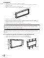
3. Place appliance face down on a soft, non-abrasive surface. Remove the bracket from the back of the
appliance by removing the screws (Fig. 4-1).
The mounting bracket must be screwed into the wall studs with at least 2 screws. If the remaining screws
cannot be screwed into a stud, ensure that plastic anchors (provided) are used to affi x the bracket to the wall
and that the bracket is adequately secured.
note:
HOOK
SCREWS
HOOK
Fig. 4-1
4. Mark out location, then mount the bracket(s) onto the wall using the supplied screws. This bracket must have
the hooks facing upward and be level.
5. With the wall mounting bracket installed, have 2 people lift the appliance up and insert the 4 bracket hooks (2
hooks per bracket) into the 2 slots on the back of the appliance.
6. Check the appliance for stability, ensuring that the bracket will not pull free from the wall.
Wall Brackets

W415-2212 / G / 02.10.20
EN
12
installation
7. Install 2 screws through the side wall mounting brackets to secure the appliance to the wall (Fig. 4-2).
8. Install side panels (see “side panel installation” section).
9. Place the crystals or optional topaz glass chips and drift wood logs (CHD models only) along the media tray
(see “crystal ember installation” and “optional topaz glass chips and drift wood log installation” sections).
10. Install front glass (see “front glass installation and removal” section).
Fig. 4-2
For NEFL42/50CHS/D models, there is only 1 wall bracket attached to the back of the appliance.
note:
Side Wall Mounting Bracket
Wood Screw
Metal Screws

EN
W415-2212 / G / 02.10.20
13
installation
Due to the many different materials used on different walls, it is highly recommended that you consult your local
builder before you install this appliance on the wall.
Select a location that is not prone to moisture and is located at least 36” (91.4cm) away from combustible
materials such curtain drapes, furniture, bedding, paper etc.
1. Measure the appliance and create a rough in with electrical. The electrical junction box is located on the left
side of the appliance.
2. Remove the front glass (see “front glass installation and removal” section).
3. Remove the plastic panel holders by removing the screws (Fig. 4-5 & 4-6).
1. Install left and right panels (Fig. 4-3) by securing 4 fasteners (2 per panel) to bottom of appliance (Fig. 4-4).
Fig. 4-3
Fig. 4-4
4.4 recessing the appliance into the wall
4.3.1 side panel installation (wall mount installation only)
Fig. 4-5
Fig. 4-6
4. If side covers are installed prior to recessed installation, remove the side covers by removing the screws (Fig.
4-7 & 4-8).
Fig. 4-8
Fig. 4-7

W415-2212 / G / 02.10.20
EN
14
installation
Fig. 4-9
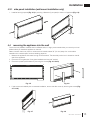
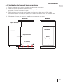
4.4.1 trim installation (recessed installation only)
1. Install left and right trims, and secure with fasteners (Fig. 4-10).
2. Install top and bottom trims, and secure with fasteners (Fig. 4-11).
Fig. 4-10 Fig. 4-11
5. Install trims (see “trim installation” section).
6. Hold the appliance up to ensure it will fi t into the framing (see “framing - recessed installation” section).
7. Apply shims (not supplied) between the appliance and the frame.
8. Use 4 screws to secure the appliance into the wall (Fig. 4-9). Do not overtighten screws.
9. Re-install the plastic panel holders.
10. Place the crystals or optional topaz glass chips and drift wood logs (CHD models only) along the media tray
(see “crystal ember installation” and “optional topaz glass chips and drift wood log installation” sections).
11. Install front glass (see “front glass installation and removal” section).
2 sets of holes are provided for recessing into the wall. The wall structure may limit how far the appliance
can be recessed. Use the appropriate set of holes when recessing to the frame. Apply shims (not supplied)
between appliance and frame.
note:
It is recommended that the walls of the appliance enclosure be fi nishing (i.e. drywall) to avoid exposed insula-
tion or vapour barrier coming in contact with the appliance. This will ensure clearance to combustibles is
maintained.
note:

EN
W415-2212 / G / 02.10.20
15
installation
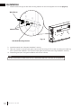
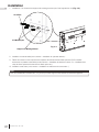
1. Remove the front glass (see “front glass installation and removal” section).
2. Install the top and bottom brackets (not supplied).
3. Insert the appliance into the mantel and secure it with the brackets. For appropriate mantel installation
instructions, consult your authorized dealer.
4. Place the crystals or optional topaz glass chips and drift wood logs (CHD models only) along the media tray
(see “crystal ember installation” and “optional topaz glass chips and drift wood log installation” sections).
5. Reinstall the front glass (see “front glass installation and removal” section).
MANTEL
TABLETTE
APPLIANCE
APPAREIL
STEP 3: SET APPLIANCE
ÉTAPES 3: RÉGLÉ APPAREIL
MANTEL
TABLETTE
APPLIANCE
APPAREIL
1/4"
STEP 1: LIFT
ÉTAPES 1: SOULEVER
STEP 2: INSERT
ÉTAPES 2: INSÉREZ
DO NOT SLIDE APPLIANCE
NE GLISSEZ PAS L'APPAREIL
!!
MANTEL
MANTEL
4.4.2 installing the appliance into a mantel

W415-2212 / G / 02.10.20
EN
16
installation
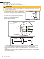
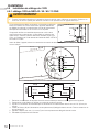
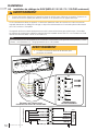
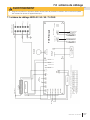
4.5 120V hard wiring installation
4.5.1 NEFL42 / 50 / 60 / 74 CHS 120V hardwiring
4
6
1
1
-
:
1
0
8
&
3
+
6
/
$
5
*
0
/
'
*
3
&
1
-
"
$
&
WHITE (N)
WHITE (N)
BLACK (L1)
BLACK (L1)
GREEN (G)
GREEN (G)
120V
1. Remove the securing screws from the electrical cover plate, located on the rear left side of the appliance.
2. Loosen the securing screws from the terminal block to remove the cord from the terminal block.
3. Add an electrical box connector and feed the supply wires through the 7/8” (22mm) hole from the terminal
block.
4. Insert White (N) wire from power supply to the designated (N) slots in the terminal block. Secure by tightening
the screws on the (N) slots.
5. Repeat step 4 with Black (L1) and Green (G), securing them to their designated slots in the terminal block.
6. Re-install cover plate.
If it is necessary to hard wire this appliance, a qualifi ed electrician
must remove the cord connection and wire the appliance directly to
the household wiring. The wire and power supply breaker must be
rated for 120V minimum 15 amps.
This appliance must be electrically connected and grounded in
accordance with local codes if hard wired. In the absence of local
codes, use the current CSA C22.1 Canadian Electrical Code in
Canada or the current ANSI/NFPA 70 National
Electrical Code in the United States.
Before hardwiring the appliance, remove the junction box control cover by removing the fasteners as shown.
!
WARNING
• Turn off the appliance completely and let cool before servicing. Only a qualifi ed service person should service
and repair this electric appliance.
WHITE (N)
BLACK (L1)
GREEN (G)
(N)
(G)
(L1)

EN
W415-2212 / G / 02.10.20
17
installation
BLACK (L1)
WHITE (N)
YELLOW (N1)
YELLOW (N2)
GREEN (G)
(G)
Jumper
Jumper
(N)
(L1)
RED (L2)
L
W
L
L
R
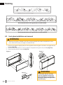
Use 2 jumper wires
to connect
N to N1 and N2.
4
6
1
1
-
:
1
0
8
&
3
+
6
/
$
5
*
0
/
'
*
3
&
1
-
"
$
&
GREEN (G)
GREEN (G)
RED (L2)
BLACK (L1)
WHITE (N)
YELLOW (N2)
YELLOW (N1)
BLACK (L1)
JUMPER
JUMPER
WHITE (N)
120V
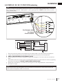
There are 5 wires from the appliance junction that connect to 120V power supply (breaker panel): 1 white (neu-
tral), 2 yellow (heater & neutral), 1 black (power L1), and 1 green (ground). Do NOT connect red wire to power
supply (breaker panel).
note:
4.5.2 NEFL42 / 50 / 60 / 74 CHD 120V hardwiring
Leave enough wire so that the appliance can be removed from the enclosure for ease of disconnecting the
power supply if the appliance needs to be serviced.
note:
1. Remove the securing screws from the electrical cover plate located on the rear left side of the appliance.
2. Loosen the securing screws from the terminal block to remove the cord from the terminal block.
3. KEEP 2 JUMPER WIRES IN THE TERMINAL BLOCK.
4. Add an electrical box connector and feed the supply wires through the 7/8” (22mm) hole from the terminal
block.
5. Insert White (N) wire from power supply to the designated (N) slots in the terminal block. Secure by tightening
the screws on the (N) slots. ENSURE JUMPER WIRES ARE SECURED.
6. Repeat step 5 with Black (L1) and Green (G), securing them to their designated slots in the terminal block.
7. Re-install cover plate.

W415-2212 / G / 02.10.20
EN
18
installation
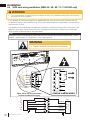
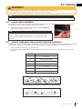
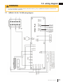
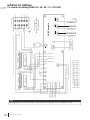
4.6 240V hard wiring installation (NEFL42 / 50 / 60 / 74 / 100 CHD only)
If it is necessary to hard wire this appliance. A qualifi ed electrician must remove the cord connection and wire
the appliance directly to the household wiring. The wire and double-pole power supply breaker must be rated for
240V minimum 15 amps.
This appliance must be electrically connected and grounded in accordance with local codes if hard wired. In the
absence of local codes, use the current CSA C22.1 Canadian Electrical Code in Canada or the current ANSI/
NFPA 70 National Electrical Code in the United States.
!
WARNING
• Turn off the appliance completely and let cool before servicing. Only a qualifi ed service person should service
and repair this electric appliance.
There are 4 wires from the appliance junction that connect to the 240V power supply (breaker panel): 1 white
(neutral), 1 black (power L1), 1 red (power L2), and 1 green (ground).
note:
BLACK (L1)
WHITE (N)
YELLOW (N1)
YELLOW (N2)
GREEN (G)
(G)
(N)
(L1)
(L2)
RED (L2)
L
W
L
L
R
(G)
(N)
(L1
)
(L2)
REMOVE JUMPER WIRES!
White, black, red, and green wires:
Connect to 240V power supply.
4
6
1
1
-
:
1
0
8
&
3
+
6
/
$
5
*
0
/
'
*
3
&
1
-
"
$
&
GREEN (G)
GREEN (G)
RED (L2)
RED (L2)
BLACK (L1)
WHITE (N)
YELLOW (N2)
YELLOW (N1)
BLACK (L1)
WHITE (N)
240V
• Failure to remove the two jumper wires may cause fi re!
WARNING

EN
W415-2212 / G / 02.10.20
19
installation
Leave enough wire so that the appliance can be removed from the enclosure for ease of disconnecting the
power supply if the appliance needs to be serviced.
note:
1. Remove the securing screws from the electrical cover plate located on the rear left side of the appliance.
2. Loosen the securing screws from the terminal block to remove the cord from the terminal block.
3. REMOVE 2 JUMPER WIRES IN THE TERMINAL BLOCK.
4. Add an electrical box connector and feed the supply wires through the 7/8” (22mm) hole from the terminal
block.
5. Insert White (N) wire from power supply to the designated (N) slots in the terminal block. Secure by tightening
the screws on the (N) slots.
6. Repeat step 5 with Black (L1), Red (L2) and Green (G), securing them to their designated slots in the terminal
block.
7. Re-install cover plate.

W415-2212 / G / 02.10.20
EN
20
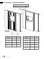
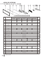
framing
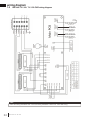
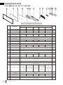
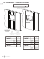
5.0 framing - recessed installation
6 1/16"
152mm
4 1/2"
89mm
MIN
MAX
JUNCTION BOX
A
B
A
B
FINISHING MATERIAL
(NON-LOAD
BEARING)
Model No. A B
NEFL42CHS
16 1/8”
(41cm)
42 9/16”
(108.1cm)
NEFL50CHS
16 1/8”
(41cm)
50 13/16”
(129.1cm)
NEFL60CHS
16 1/8”
(41cm)
60 11/16”
(154.1cm)
NEFL74CHS
16 1/8”
(41cm)
74 13/16”
(190cm)
Measurements from body of appliance:
Sides, Back, Top
0”
Model No. A B
NEFL42CHD
16 1/8”
(41cm)
42 9/16”
(108.1cm)
NEFL50CHD
16 1/8”
(41cm)
50 13/16”
(129.1cm)
NEFL60CHD
16 1/8”
(41cm)
60 11/16”
(154.1cm)
NEFL74CHD
16 1/8”
(41cm)
74 13/16”
(190cm)
NEFL100CHD
16 1/8”
(41cm)
100 13/16”
(256.1cm)
4 1/2”
[89mm]
minimum for CHS
models
6 1/16”
[152mm]
minimum for CHD
models
La page charge ...
La page charge ...
La page charge ...
La page charge ...
La page charge ...
La page charge ...
La page charge ...
La page charge ...
La page charge ...
La page charge ...
La page charge ...
La page charge ...
La page charge ...
La page charge ...
La page charge ...
La page charge ...
La page charge ...
La page charge ...
La page charge ...
La page charge ...
La page charge ...
La page charge ...
La page charge ...
La page charge ...
La page charge ...
La page charge ...
La page charge ...
La page charge ...
La page charge ...
La page charge ...
La page charge ...
La page charge ...
La page charge ...
La page charge ...
La page charge ...
La page charge ...
La page charge ...
La page charge ...
La page charge ...
La page charge ...
La page charge ...
La page charge ...
La page charge ...
La page charge ...
La page charge ...
La page charge ...
La page charge ...
La page charge ...
-
 1
1
-
 2
2
-
 3
3
-
 4
4
-
 5
5
-
 6
6
-
 7
7
-
 8
8
-
 9
9
-
 10
10
-
 11
11
-
 12
12
-
 13
13
-
 14
14
-
 15
15
-
 16
16
-
 17
17
-
 18
18
-
 19
19
-
 20
20
-
 21
21
-
 22
22
-
 23
23
-
 24
24
-
 25
25
-
 26
26
-
 27
27
-
 28
28
-
 29
29
-
 30
30
-
 31
31
-
 32
32
-
 33
33
-
 34
34
-
 35
35
-
 36
36
-
 37
37
-
 38
38
-
 39
39
-
 40
40
-
 41
41
-
 42
42
-
 43
43
-
 44
44
-
 45
45
-
 46
46
-
 47
47
-
 48
48
-
 49
49
-
 50
50
-
 51
51
-
 52
52
-
 53
53
-
 54
54
-
 55
55
-
 56
56
-
 57
57
-
 58
58
-
 59
59
-
 60
60
-
 61
61
-
 62
62
-
 63
63
-
 64
64
-
 65
65
-
 66
66
-
 67
67
-
 68
68


NAPOLEON ALLURAVISION Series Manuel utilisateur
- Taper
- Manuel utilisateur
dans d''autres langues
Documents connexes
-
NAPOLEON NEFL60CHD Manuel utilisateur
-
NAPOLEON NEFL42CHD Manuel utilisateur
-
-
-
-
-
-
-
-


