Hitachi H 60MR Manuel utilisateur
- Catégorie
- Marteaux rotatifs
- Taper
- Manuel utilisateur
Ce manuel convient également à

DOUBLE INSULATION
DOUBLE ISOLATION
AISLAMIENTO DOBLE
MODE D’EMPLOI ET INSTRUCTIONS DE SECURITE
AVERTISSEMENT
Une utilisation incorrecte et dangereuse de cet outil motorisé peut entraîner la
mort ou de sérieuses blessures corporelles!
Ce mode d’emploi contient d’importantes informations à propos de la sécurité
de ce produit. Prière de lire et de comprendre ce mode d’emploi avant d’utiliser
l’outil motorisé. Garder ce mode d’emploi à la disponibilité des autres utilisateurs
avant qu’ils utilisent l’outil motorisé.
INSTRUCTION MANUAL AND SAFETY INSTRUCTIONS
WARNING
Improper and unsafe use of this power tool can result in death or serious bodily
injury!
This manual contains important information about product safety. Please read
and understand this manual before operating the power tool. Please keep this
manual available for others before they use the power tool.
MANUAL DE INSTRUCCIONES E INSTRUCCIONES DE SEGURIDAD
ADVERTENCIA
¡La utilización inapropiada e insegura de esta herramienta eléctrica puede resultar
en lesiones serias o en la muerte!
Este manual contiene información importante sobre la seguridad del producto.
Lea y comprenda este manual antes de utilizar la herramienta eléctrica. Guarde
este manual para que puedan leerlo otras personas antes de que utilicen la
herramienta eléctrica.
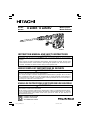
H60MRV
Model Demolition Hammer
Modèle Marteau piqueur
Modelo Martillo demoledor
H 60MR
•
H 60MRV
01Eng_H60MR_US 10/26/07, 18:371

English
2
CONTENTS
Page
IMPORTANT SAFETY INFORMATION ...... 3
MEANINGS OF SIGNAL WORDS .............. 3
SAFETY ............................................................ 4
GENERAL SAFETY RULES ......................... 4
SPECIFIC SAFETY RULES AND
SYMBOLS.............................................. 6
DOUBLE INSULATION FOR SAFER
OPERATION .......................................... 8
FUNCTIONAL DESCRIPTION ......................... 9
NAME OF PARTS ........................................ 9
SPECIFICATIONS ........................................ 9
Page
ASSEMBLY .................................................... 10
OPERATION .................................................. 12
APPLICATIONS ......................................... 12
PRIOR TO OPERATION ............................. 12
HOW TO USE THE DEMOLITION
HAMMER ............................................. 13
MAINTENANCE AND INSPECTION ............. 14
ACCESSORIES .............................................. 16
STANDARD ACCESSORIES ..................... 16
OPTIONAL ACCESSORIES ....................... 16
TABLE DES MATIERES
Page
INFORMATIONS IMPORTANTES DE
SÉCURITÉ ............................................ 18
SIGNIFICATION DES MOTS
D’AVERTISSEMENT ........................... 18
SECURITE ...................................................... 19
REGLES GENERALES DE SECURITE ....... 19
REGLES DE SECURITE SPECIFIQUES
ET SYMBOLES .................................... 21
DOUBLE ISOLATION POUR UN
FONCTIONNEMENT PLUS SUR ........ 23
DESCRIPTION FONCTIONNELLE ................ 24
NOM DES PARTIES .................................. 24
SPECIFICATIONS ...................................... 24
Page
ASSEMBLAGE .............................................. 25
FONCTIONNEMENT ..................................... 27
APPLICATIONS ......................................... 27
AVANT L’UTILISATION ............................ 27
COMMENT UTILISER LE MARTEAU
PIQUEUR ............................................. 28
ENTRETIEN ET INSPECTION ....................... 29
ACCESOIRES ................................................. 31
ACCESSOIRES STANDARD ..................... 31
ACCESSOIRES SUR OPTION ................... 31
ÍNDICE
Página
INFORMACIÓN IMPORTANTE SOBRE
SEGURIDAD ........................................ 33
SIGNIFICADO DE LAS PALABRAS DE
SEÑALIZACIÓN................................... 33
SEGURIDAD .................................................. 34
NORMAS GENERALES DE SEGURIDAD
............................................................. 34
NORMAS Y SÍMBOLOS ESPECÍFICOS
DE SEGURIDAD .................................. 36
AISLAMIENTO DOBLE PARA OFRECER
UNA OPERACIÓN MÁS SEGURA ..... 38
DESCRIPCIÓN FUNCIONAL ......................... 39
NOMENCLATURA ..................................... 39
ESPECIFICACIONES .................................. 39
Página
MONTAJE ..................................................... 40
OPERACIÓN .................................................. 42
APLICACIONES ......................................... 42
ANTES DE LA OPERACIÓN ...................... 42
FORMA DE USAR EL MARTILLO
DEMOLEDOR ...................................... 43
MANTENIMIENTO E INSPECCIÓN .............. 44
ACCESORIOS ................................................ 46
ACCESORIOS ESTÁNDAR ....................... 46
ACCESORIOS OPCIONALES .................... 46
English
Español
Français
01Eng_H60MR_US 10/26/07, 18:372

English
3
IMPORTANT SAFETY INFORMATION
Read and understand all of the safety precautions, warnings and operating instructions in
the Instruction Manual before operating or maintaining this power tool.
Most accidents that result from power tool operation and maintenance are caused by the
failure to observe basic safety rules or precautions. An accident can often be avoided by
recognizing a potentially hazardous situation before it occurs, and by observing appropriate
safety procedures.
Basic safety precautions are outlined in the “SAFETY” section of this Instruction Manual
and in the sections which contain the operation and maintenance instructions.
Hazards that must be avoided to prevent bodily injury or machine damage are identified by
WARNINGS on the power tool and in this Instruction Manual.
NEVER use this power tool in a manner that has not been specifically recommended by
HITACHI.
MEANINGS OF SIGNAL WORDS
WARNING indicates a potentially hazardous situation which, if ignored, could result in death
or serious injury.
CAUTION indicates a potentially hazardous situation which, if not avoided, may result in
minor or moderate injury, or may cause machine damage.
NOTE emphasizes essential information.
01Eng_H60MR_US 10/26/07, 18:373

English
4
SAFETY
GENERAL SAFETY RULES
WARNING: Read and understand all instructions.
Failure to follow all instructions listed below, may result in electric shock,
fire and/or serious personal injury.
SAVE THESE INSTRUCTIONS
1. Work Area
(1) Keep your work area clean and well lit. Cluttered benches and dark areas invite
accidents.
(2) Do not operate power tools in explosive atmospheres, such as in the presence of
flammable liquids, gases, or dust. Power tools create sparks which may ignite the
dust of fumes.
(3) Keep bystanders, children, and visitors away while operating a power tool.
Distractions can cause you to lose control.
2. Electrical Safety
(1) Double Insulated tools are equipped with a polarized plug (one blade is wider than
the other.) This plug will fit in a polarized outlet only one way. If the plug does not
fit fully in the outlet, reverse the plug. If it still does not fit, contact a qualified
electrician to install a polarized outlet. Do not change the plug in any way. Double
Insulation
eliminates the need for the three wire grounded power cord and
grounded power supply system.
(2) Avoid body contact with grounded surfaces such as pipes, radiators, ranges and
refrigerators. There is an increased risk of electric shock if your body is grounded.
(3) Don’t expose power tools to rain or wet conditions. Water entering a power tool
will increase the risk of electric shock.
(4) Do not abuse the cord. Never use the cord to carry the tools or pull the plug from
a receptacle. Keep cord away from heat, oil, sharp edges or moving parts. Replace
damaged cords immediately. Damaged cords increase the risk of electric shock.
(5) When operating a power tool outside, use an outdoor extension cord marked “W-
A” or “W”. These cords are rated for outdoor use and reduce the risk of electric
shock.
3. Personal Safety
(1) Stay alert, watch what you are doing and use common sense when operating a
power tool. Do not use tool while tired or under the influence of drugs, alcohol, or
medication. A moment of inattention while operating power tools may result in
serious personal injury.
(2) Dress properly. Do not wear loose clothing or jewelry. Contain long hair. Keep
your hair, clothing, and gloves away from moving parts. Loose clothes, jewelry, or
long hair can be caught in moving parts.
(3) Avoid accidental starting. Be sure switch is off before plugging in. Carrying tools
with your finger on the switch or plugging in tools that have the switch on invites
accidents.
01Eng_H60MR_US 10/26/07, 18:374

English
5
(4) Remove adjusting keys or wrenches before turning the tool on. A wrench or a key
that is left attached to a rotating part of the tool may result in personal injury.
(5) Do not overreach. Keep proper footing and balance at all times. Proper footing and
balance enables better control of the tool in unexpected situations.
(6) Use safety equipment. Always wear eye protection. Dust mask, non-skid safety
shoes, hard hat, or hearing protection must be used for appropriate conditions.
4. Tool Use and Care
(1) Use clamps or other practical way to secure and support the workpiece to a stable
platform. Holding the work by hand or against your body is unstable and may lead
to loss of control.
(2) Do not force tool. Use the correct tool for your application. The correct tool will do
the job better and safer at the rate for which it is designed.
(3) Do not use tool if switch does not turn it on or off. Any tool that cannot be controlled
with the switch is dangerous and must be repaired.
(4) Disconnect the plug from the power source before making any adjustments,
changing accessories, or storing the tool. Such preventive safety measures reduce
the risk of starting the tool accidentally.
(5) Store idle tools out of reach of children and other untrained persons. Tools are
dangerous in the hand of untrained users.
(6) Maintain tools with care. Keep cutting tools sharp and clean. Properly maintained
tools, with sharp cutting edges are less likely to bind and are easier to control.
(7) Check for misalignment or binding of moving parts, breakage of parts, and any
other condition that may affect the tools operation. If damaged, have the tool
serviced before using. Many accidents are caused by poorly maintained tools.
(8) Use only accessories that are recommended by the manufacturer for your model.
Accessories that may be suitable for one tool, may become hazardous when used
on another tool.
5. Service
(1) Tool service must be performed only by qualified repair personnel. Service or
maintenance performed by unqualified personnel could result in a risk of injury.
(2) When servicing a tool, use only identical replacement parts. Follow instructions in
the Maintenance section of this manual. Use of unauthorized parts or failure to
follow Maintenance Instruction may create a risk of electric shock or injury.
01Eng_H60MR_US 10/26/07, 18:375

English
6
SPECIFIC SAFETY RULES AND SYMBOLS
1. Hold tools by insulated gripping surfaces when performing an operation where the
cutting tool may contact hidden wiring or its own cord. Contact with a “live” wire will
make exposed metal parts of the tool “live” and shock the operator.
2. ALWAYS wear ear protectors when using the tool for extended periods.
Prolonged exposure to high intensity noise can cause hearing loss.
3. Never touch moving parts.
Never place your hands, fingers or other body parts near the tool’s moving parts.
4. Never operate without all guards in place.
Never operate this tool without all guards or safety features in place and in proper
working order. If maintenance or servicing requires the removal of a guard or safety
feature, be sure to replace the guard or safety feature before resuming operation of the
tool.
5. Use right tool.
Don’t force small tool or attachment to do the job of a heavy-duty tool.
Don’t use tool for purpose not intended —for example— don’t use circular saw for
cutting tree limbs or logs.
6. Never use a power tool for applications other than those specified.
Never use a power tool for applications other than those specified in the Instruction
Manual.
7. Handle tool correctly.
Operate the tool according to the instructions provided herein. Do not drop or throw
the tool. Never allow the tool to be operated by children, individuals unfamiliar with its
operation or unauthorized personnel.
8. Keep all screws, bolts and covers tightly in place.
Keep all screws, bolts, and plates tightly mounted. Check their condition periodically.
9. Do not use power tools if the plastic housing or handle is cracked.
Cracks in the tool’s housing or handle can lead to electric shock. Such tools should not
be used until repaired.
10. Blades and accessories must be securely mounted to the tool.
Prevent potential injuries to yourself or others. Blades, cutting implements and
accessories which have been mounted to the tool should be secure and tight.
11. Keep motor air vent clean.
The tool’s motor air vent must be kept clean so that air can freely flow at all times.
Check for dust build-up frequently.
12. Operate power tools at the rated voltage.
Operate the power tool at voltages specified on its nameplate.
If using the power tool at a higher voltage than the rated voltage, it will result in
abnormally fast motor revolution and may damage the unit and the motor may burn
out.
01Eng_H60MR_US 10/26/07, 18:376

English
7
13. Never use a tool which is defective or operating abnormally.
If the tool appears to be operating unusually, making strange noises, or otherwise
appears defective, stop using it immediately and arrange for repairs by a Hitachi
authorized service center.
14. Never leave tool running unattended. Turn power off.
Don’t leave tool until it comes to a complete stop.
15. Carefully handle power tools.
Should a power tool be dropped or struck against hard materials inadvertently, it may
be deformed, cracked, or damaged.
16. Do not wipe plastic parts with solvent.
Solvents such as gasoline, thinner benzine, carbon tetrachloride, and alcohol may
damage and crack plastic parts. Do not wipe them with such solvents.
Wipe plastic parts with a soft cloth lightly dampened with soapy water and dry
thoroughly.
17. ALWAYS wear eye protection that meets the requirement of the latest revision of ANSI
Standard Z87.1.
18. NEVER touch the tool bit with bare hands after operation.
19. NEVER wear gloves made from materials likely to roll up such as cotton, wool, cloth or
string, etc.
20. ALWAYS attach the side handle and securely grip the Demolition Hammer.
21. ALWAYS be careful with buried object such as an underground wiring.
Touching live wiring or electric cable with this tool may result in electric shock.
Confirm before use whether hidden objects are present, such as electric cables within
the wall, floor or ceiling.
22. Definitions for symbols used on this tool
V ............. volts
Hz ........... hertz
A ............. amperes
no .......... no load speed
W ............ watt
............ Class II Construction
---/min .... revolutions per minute
........... Alternating current
01Eng_H60MR_US 10/26/07, 18:377

English
8
DOUBLE INSULATION FOR SAFER OPERATION
To ensure safer operation of this power tool, HITACHI has adopted a double insulation
design. “Double insulation” means that two physically separated insulation systems have
been used to insulate the electrically conductive materials connected to the power supply
from the outer frame handled by the operator. Therefore, either the symbol “
” or the
words and “Double insulation” appear on the power tool or on the nameplate.
Although this system has no external grounding, you must still follow the normal electrical
safety precautions given in this Instruction Manual, including not using the power tool in
wet environments.
To keep the double insulation system effective, follow these precautions:
䡬 Only HITACHI AUTHORIZED SERVICE CENTER should disassemble or assemble this
power tool, and only genuine HITACHI replacement parts should be installed.
䡬 Clean the exterior of the power tool only with a soft cloth moistened with soapy water,
and dry thoroughly.
Never use solvents, gasoline or thinners on plastic components; otherwise the plastic
may dissolve.
SAVE THESE INSTRUCTIONS
AND
MAKE THEM AVAILABLE TO
OTHER USERS
AND
OWNERS OF THIS TOOL!
01Eng_H60MR_US 10/26/07, 18:378

English
9
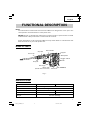
Fig. 1
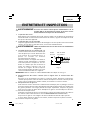
Model H60MR H60MRV
Motor Single-Phase, Series Commutator Motor
Power Source Single-Phase, 120 V AC 60Hz
Current 11.8 A 12.5 A
Full-load Impact Rate 1,650/min. 930 – 1,650/min.
Weight 23.1 lbs (10.5 kg)
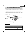
FUNCTIONAL DESCRIPTION
NOTE:
The information contained in this Instruction Manual is designed to assist you in the
safe operation and maintenance of the power tool.
NEVER operate, or attempt any maintenance on the tool unless you have first read and
understood all safety instructions contained in this manual.
Some illustrations in this Instruction Manual may show details or attachments that
differ from those on your own power tool.
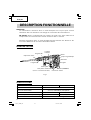
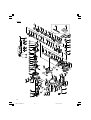
NAME OF PARTS
SPECIFICATIONS
Nameplate
Side Handle
Front Cap
Grip (B)
Grip (A)
Trigger Switch
Stopper
Dial (H60MRV)
Tail Cover
Housing
Brush Cap
(Under the Tail Cover)
Handle
01Eng_H60MR_US 10/26/07, 18:379

English
10
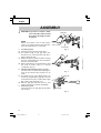
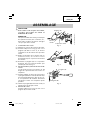
ASSEMBLY
CAUTION: To prevent accidents, make
sure to turn the switch off and
disconnect the plug from the
receptacle.
NOTE:
When using tools such as bull points,
cutters, etc., make sure to use the genuine
parts designated by our company.
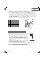
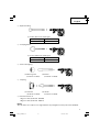
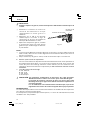
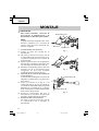
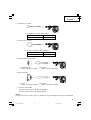
1. Installing Tools
(1) Clean the shank portion of the tool.
(2) As shown in Fig. 2, pull grip (A) in the
direction of A, and insert the tool into a
hole of the front cap.
(3) Adjust the groove position while turning
the tool, and furthermore insert it until it
hits the end of the hole.
(4) Return grip (A) to its original position, pull
the tool to make sure it is locked
completely. (Fig. 3)
2. Deciding Working Position of Tool
The tool can be turned every 30 degrees
and can be fixed at the position of 12
steps.
(1) As shown in Fig. 4, the blade angle can
be freely changed if the grip (A) is turned
in the direction of B in a state where grip
(B) is slid in the direction of A.
(2) Release grip (B) and turn the tool, and
make sure that it is locked completely.
3. Removing Tool
As shown in Fig. 2, pull grip (A), and pull
out the tool.
Fig. 2
Grip (A)
Tool Shank
Front Cap
A
Fig. 3
Fig. 4
Grip (B)
A
B
Grip (A)
01Eng_H60MR_US 10/26/07, 18:3710

English
11
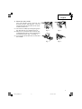
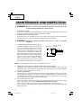
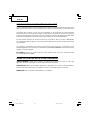
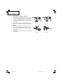
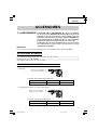
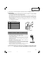
4. Move the side handle
The side handle can be fixed at any
desired position; 360 degrees, and can
also be fixed at any position in the back-
and-forth direction.
(1) Loosen the handle by turning the grip in
the direction of A as shown in Fig. 5.
(2) Adjust it to a position where vertical (up-
and-down) operation can be facilitated as
illustrated in Fig. 6, Fig. 7, and Fig. 8.
(3) Turn the grip in the direction of B and fix
the handle.
Fig. 7 Fig. 8
Fig. 5 Fig. 6
Grip
A
B
01Eng_H60MR_US 10/26/07, 18:3711

English
12
OPERATION
APPLICATIONS
䡬 Demolishing concrete, chiseling concrete, grooving, bar cutting, and driving piles.
Application examples:
Installation of piping and wiring, sanitary facility installation, machinery installation,
water supply and drainage work, interior jobs, harbor facilities and other civil engineering
work.
PRIOR TO OPERATION
1. Power source
Ensure that the power source to be utilized conforms to the power source requirements
specified on the product nameplate.
2. Power switch
Ensure that the switch is in the OFF position. If the plug is connected to a receptacle
while the switch is in the ON position, the power tool will start operating immediately
and can cause serious injury.
3. Extension cord
When the work area is far away from the power source, use an extension cord of
sufficient thickness and rated capacity. The extension cord should be kept as short as
practicable.
WARNING: Damaged cord must be replaced or repaired.
4. Check the receptacle
If the receptacle only loosely accepts the plug, the receptacle must be repaired. Contact
a licensed electrician to make appropriate repairs.
If such a faulty receptacle is used, it may cause overheating, resulting in a serious
hazard.
5. Confirming condition of the environment:
Confirm that the work site is placed under appropriate conditions conforming to
prescribed precautions.
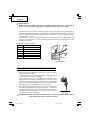
6. Select the number of strikes (applicable only to H60MRV) (Fig. 9)
01Eng_H60MR_US 10/26/07, 18:3712

English
13
HOW TO USE THE DEMOLITION HAMMER
1. After placing the tip of the tool on concrete surface, switch
ON.
The switch can be turned ON if the trigger is pulled and OFF
when it is released.
If the stopper is pressed while the trigger for the switch is
pulled, even if your finger is released from the trigger, the
switch remains ON - convenient for continuous operation.
To turn the switch OFF, pull the trigger again, and then the
stopper comes off.
2. By utilizing the empty weight of the machine and by firmly
holding the demolition hammer with both hands, one can
effectively control the subsequent recoil motion.
Proceed at a moderate work-rate, the use of too much force will impair efficiency.
CAUTION: After long time of use, the cylinder case becomes hot.
Therefore, be careful not to burn your hands.
Standard number of strikes
Dial Number of strikes/min.
6 1,650
5 1,590
4 1,460
3 1,320
2 1,110
1 930
Fig. 9 (H60MRV)
Dial
Fig. 10
CAUTION: Do not make any adjustment of the dial during operation. Holding the main
body with one hand can swing you around, resulting in an injury.
This machine has an electronic controlled circuit built-in, enabling stepless regulation
of the number of strikes. Make the most of this machine by adjusting the dial according
to the working contents; chiseling, demolishing, or the quality of the material to be
chiseling or demolishing.
The scale “1” of the dial is for the minimum speed with 930 strikes per minute, and the
scale “6” is for the maximum speed with 1,650 strikes per minute.
01Eng_H60MR_US 10/26/07, 18:3713

English
14
MAINTENANCE AND INSPECTION
WARNING: Be sure to switch power OFF and disconnect the plug from the
receptacle during maintenance and inspection.
1. Inspecting the tool
Since use of a dull tool will degrade efficiency and cause possible motor malfunction,
sharpen or replace the tool as soon as abrasion is noted.
2. Inspecting the mounting screws
Regularly inspect all mounting screws and ensure that they are properly tightened.
Should any of the screws be loosened, retighten them immediately.
WARNING: Using this demolition hammer with loosen screws is extremely
dangerous.
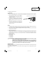
3. Inspecting the carbon brushes (Fig. 11)
The Motor employs carbon brushes which
are consumable parts. When they become
worn to or near the “wear limit”, it could
result in motor trouble. When an auto-stop
carbon brush is equipped, the motor will
stop automatically. At that time, replace
both carbon brushes with new ones which
have the same carbon brush Numbers
shown in the figure. In addition, always
keep carbon brushes clean and ensure that
they slide freely within the brush holders.
NOTE: Use HITACHI carbon brush No. 74 indicated in Fig. 11.
4. Replacing carbon brushes (Refer to figure for name of parts)
Loosen the set screw then remove the tail cover. By loosening the brush caps, the
carbon brushes can be removed. After fitting new carbon brushes, properly retighten
the brush caps and mount the tail cover.
5. Grease replacement
This machine is of fully oil sealed construction to protect against dust incursion and to
prevent lubricant leakage. This machine can be used without grease replenishment for
an extended period of time. However, perform the grease replacement to extend the
service life. Replace the grease as described below.
(1) Grease Replacement Period
Inspect the grease amount according to the timing replacement period of the carbon
brush. (See item 3 in the section MAINTENANCE AND INSPECTION.)
Ask for grease replacement at the nearest authorized Hitachi Service Center.
In the case that you are forced to change the grease by yourself, please follow the
following points.
74
Wear limit
0.28” (7 mm)
No. of carbon
brush
0.67” (17 mm)
Fig. 11
01Eng_H60MR_US 10/26/07, 18:3714

English
15
(2) How to replace grease
CAUTION:
䡬 Before replacing the grease, turn the power off and pull out the plug from the receptacle.
1 Disassemble the crank case cover and the
crank cover and thoroughly wipe off the
old grease inside.
2 Supply 2.7 oz (80 g) (the standard volume
to cover the connecting rod) of Hitachi
Electric Hammer Grease A in the crank
case.
3 After replacing the grease, reassemble the
crank case cover and the crank cover
securely. At this time, do not damage or
lose the oil seal.
NOTE:
䡬 The Hitachi Electric Hammer Grease A is of the low viscosity type. When the grease is
consumed, purchase from the authorized Hitachi Service Center.
䡬 Do not excessively supply the designated amount of grease. Otherwise, the tool should
not operate accurately.
6. Service and repairs
All quality power tools will eventually require servicing or replacement of parts because
of wear from normal use. To assure that only authorized replacement parts will be
used, all service and repairs must be performed by a HITACHI AUTHORIZED SERVICE
CENTER, ONLY.
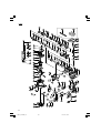
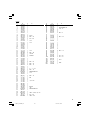
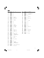
7. Service parts list
A: Item No.
B: Code No.
C: No. Used
D: Remarks
CAUTION: Repair, modification and inspection of Hitachi Power Tools must be carried
out by a Hitachi Authorized Service Center.
This Parts List will be helpful if presented with the tool to the Hitachi
Authorized Service Center when requesting repair or other maintenance. In
the operation and maintenance of power tools, the safety regulations and
standards prescribed in each country must be observed.
MODIFICATIONS:
Hitachi Power Tools are constantly being improved and modified to incorporate the latest
technological advancements.
Accordingly, some parts (i.e. code numbers and/or design) may be changed without prior
notice.
Crank Case Cover
Fig. 12
Crank Cover
01Eng_H60MR_US 10/26/07, 18:3715

English
16
ACCESSORIES
WARNING: ALWAYS use Only authorized HITACHI replacement parts and
accessories. NEVER use replacement parts or accessories which are
not intended for use with this tool. Contact HITACHI if you are not sure
whether it is safe to use a particular replacement part or accessory
with your tool.
The use of any other attachment or accessory can be dangerous and
could cause injury or mechanical damage.
NOTE:
Accessories are subject to change without any obligation on the part of the HITACHI.
STANDARD ACCESSORIES
(1) Bull Point (SDS max shank) (Code No. 313471) ................................................................ 1
(2) Case (Code No. 324049) ...................................................................................................... 1
(3) Side Handle (Code No. 317103) .......................................................................................... 1
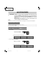
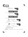
OPTIONAL ACCESSORIES........ sold separately
䡬 Demolishing
(1) Bull Point (SDS max shank type)
䡬 Groove digging and edging
(1) Cold chisel (SDS max shank type)
Overall Length 11-1/32" (280 mm) 15-3/4" (400 mm)
Code No. 313473 313474
Overall Length 11-1/32" (280 mm) 15-3/4" (400 mm)
Code No. 313471 313472
01Eng_H60MR_US 10/26/07, 18:3716

English
17
䡬 Asphalt Cutting
(1) Cutter (SDS max shank type)
䡬 Scooping Work
(1) Scoop (SDS max shank type)
䡬 Surface Roughing
䡬 Tamping
䡬 Hammer Grease A
70g (in a tube) (Code No. 981840)
30g (in a tube) (Code No. 308471)
NOTE:
Specifications are subject to change without any obligation on the part of the HITACHI.
(1) Bushing Tool
(Code No. 313477)
(2) Shank
(Code No. 313479)
(1) Rammer
(Code No. 313478)
(2) Shank
(Code No. 313479)
Overall Length 15-3/4" (400 mm)
Code No. 313475
Overall Length 15-3/4" (400 mm)
Code No. 313476
01Eng_H60MR_US 10/26/07, 18:3717

18
Français
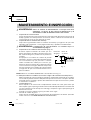
INFORMATIONS IMPORTANTES DE SÉCURITÉ
Lire et comprendre toutes les précautions de sécurité, les avertissements et les instructions
de fonctionnement dans ce mode d’emploi avant d’utiliser ou d’entretenir cet outil motorisé.
La plupart des accidents causés lors de l’utilisation ou de l’entretien de l’outil motorisé
proviennent d’un non respect des règles ou précautions de base de sécurité. Un accident
peut la plupart du temps être évité si l’on reconnaît une situation de danger potentiel avant
qu’elle ne se produise, et en observant les procédures de sécurité appropriées.
Les précautions de base de sécurité sont mises en évidence dans la section “SECURITE”
de ce mode d’emploi et dans les sections qui contiennent les instructions de fonctionnement
et d’entretien.
Les dangers qui doivent être évités pour prévenir des blessures corporelles ou un
endommagement de la machine sont identifiés par AVERTISSEMENTS sur l’outil motorisé
et dans ce mode d’emploi.
NE JAMAIS utiliser cet outil motorisé d’une manière qui n’est pas spécifiquement
recommandée par HITACHI.
SIGNIFICATION DES MOTS D’AVERTISSEMENT
AVERTISSEMENT indique des situations potentiellement dangereuses qui, si elles sont
ignorées, pourraient entraîner la mort ou de sérieuses blessures.
PRECAUTION indique des situations dangereuses potentilles qui, si elles ne sont pas évitées,
peuvent entraîner de mineures et légères blessures ou endommager la machine.
REMARQUE met en relief des informations essentielles.
02Fre_H60MR_US 10/26/07, 18:3818

19
Français
SECURITE
REGLES GENERALE DE SECURITE
AVERTISSEMENT: Lire et coxmprendre toutes les instructions.
Un non respect de toutes les instructions ci-dessous peut
entraîner une électrocution, un incendie et/ou de sérieuses
blessures personnelles.
CONSERVER CES INSTRUCTIONS
1. Zone de travail
(1) Garder la zone de travail propre et bien éclairée. Les établis mal rangés et les
zones sombres invitent aux accidents.
(2) Ne pas utiliser les outils motorisés dans une atmosphère explosive, telle qu’en
présence de liquides inflammables, de gaz ou de poussières. Les outils motorisés
créent des étincelles qui risquent d’enflammer la poussière ou les vapeurs.
(3) Tenir les spectateurs, les enfants et les visiteurs éloignés, lors de l’utilisation de
l’outil motorisé. Une distraction peut faire perdre le contrôle de la machine.
2. Sécurité électrique
(1) Les outils à double isolation sont équipés d’une fiche polarisée (une lame est plus
large que l’autre). Cette fiche ne pénétrera dans une prise secteur polarisée que
dans un sens. Si la fiche ne rentre pas complètement dans la prise, la retourner. Si
elle ne rentre toujours pas, contacter un électricien qualifié pour installer une prise
polarisée. Ne pas modifier la fiche d’aucune façon. La double isolation
élimine
le besoin d’un cordon d’alimentation à trois fils et d’un système d’alimentation
avec mises à la terre.
(2) Eviter tout contact corporel avec les surfaces mises à la terre telles que les
canalisations, les radiateurs, les réchauds et les réfrigérateurs. Il y a un risque
accru d’électrocution si son corps est mis à la terre.
(3) Ne pas exposer les outils motorisés à la pluie ou à l’humidité. De l’eau pénétrant à
l’intérieur de l’outil motorisé augmente le risque d’électrocution.
(4) Ne pas maltraiter le cordon d’alimentation. Ne jamais utiliser le cordon pour porter
les outils ou tirer sur la fiche du réceptacle. Garder le cordon à l’écart de la chaleur,
de l’huile, des arêtes coupantes ou des pièces en mouvement. Remplacer les
cordons endommagés immédiatement. Des cordons endommagés augmentent le
risque d’électrocution.
(5) Lors de l’utilisation d’un outil motorisé, utiliser un cordon de rallonge extérieur
marqué “W-A” ou “W”. Ces cordons sont prévus pour une utilisation extérieure et
réduisent les risques d’électrocution.
3. Sécurité personnelle
(1) Rester sur ses gardes, regarder ce que l’on fait et utiliser son sens commun lors de
l’utilisation d’un outil motorisé. Ne pas utiliser un outil en état de fatigue ou sous
l’influence de drogues, d’alcool ou de médicaments. Un moment d’inattention lors
de l’utilisation de l’outil motorisé peut entraîner de sérieuses blessures personnelles.
(2) S’habiller correctement. Ne pas porter des vêtements larges ou des bijoux. Attacher
les cheveux longs. Tenir ses cheveux, vêtements et ses gants éloignés des parties
mobiles. Les vêtements larges, les bijoux et les cheveux longs peuvent se prendre
dans les parties mobiles.
02Fre_H60MR_US 10/26/07, 18:3819

20
Français
(3) Eviter tout démarrage accidentel. S’assurer que le l’interrupteur d’alimentation
est sur la position d’arrêt avant de brancher la machine. Transporter l’appareil
avec les doigts sur l’interrupteur d’alimentation ou brancher un outil avec
l’interrupteur sur la position marche invite aux accidents.
(4) Retirer les clefs d’ajustement ou les commutateurs avant de mettre l’outil sous
tension. Une clef qui est laissée attachée à une partie tournante de l’outil peut
provoquer une blessure personnelle.
(5) Ne pas trop présumer de ses forces. Garder en permanence une position et un
équilibre correct. Une position et un équilibre correct permettent un meilleur contrôle
de l’outil dans des situations inattendues.
(6) Utiliser un équipement de sécurité. Toujours porter des lunettes de protection.
Utiliser un masque à poussière, des chaussures de sécurité antidérapantes, un
couvre-chef dur ou des protections d’oreille dans les conditions appropriées.
4. Utilisation de l’outil et entretien
(1) Utiliser un étau ou toutes autres façons de fixer et maintenir la pièce à usiner sur
une plate-forme stable. Tenir la pièce avec la main ou contre son corps est instable
et peut conduire à une perte de contrôle de l’outil.
(2) Ne pas forcer sur l’outil. Utiliser l’outil correct pour l’application souhaitée. L’outil
correct réalisera un meilleur et plus sûr travail dans le domaine pour lequel il a été
conçu.
(3) Ne pas utiliser un outil s’il ne se met pas sous ou hors tension avec un interrupteur.
Un outil qui ne peut pas être commandé avec un interrupteur est dangereux et doit
être réparé.
(4) Déconnecter la fiche de la source d’alimentation avant de réaliser tout ajustement,
changement d’accessoires ou pour ranger l’outil. De telles mesures de sécurité
réduisent le risque que l’outil ne démarre accidentellement.
(5) Ranger les outils inutilisés hors de la portée des enfants et des autres personnes
inexpérimentées. Les outils sont dangereux dans les mains de personnes
inexpérimentées.
(6) Conserver les outils avec soin. Garder les outils de coupe aiguisés et propres. Des
outils bien entretenus, avec des lames coupantes aiguisées risquent moins de se
gripper et sont plus faciles à contrôler.
(7) Vérifier les défauts d’alignement ou grippage des parties mobiles, les ruptures
des pièces et toutes les autres conditions qui peuvent affecter le fonctionnement
des outils. En cas de dommage, faire réparer l’outil avant de l’utiliser. Beaucoup
d’accidents sont causés par des outils mal entretenus.
(8) Utiliser uniquement les accessoires recommandés par le fabricant pour le modèle
utilisé. Des accessoires qui peuvent convenir à un outil, peuvent devenir dangereux
lorsqu’ils sont utilisés avec un autre outil.
5. Réparation
(1) La réparation de l’outil ne doit être réalisée uniquement par un réparateur qualifié.
Une réparation ou un entretien réalisé par un personnel non qualifié peut entraîner
des risques de blessures.
(2) Lors de la réparation d’un outil, utiliser uniquement des pièces de rechange
identiques. Suivre les instructions de la section d’entretien de ce mode d’emploi.
L’utilisation de pièces non autorisées ou un non respect des instructions d’entretien
peut créer un risque d’électrocution ou de blessures.
02Fre_H60MR_US 10/26/07, 18:3820
La page est en cours de chargement...
La page est en cours de chargement...
La page est en cours de chargement...
La page est en cours de chargement...
La page est en cours de chargement...
La page est en cours de chargement...
La page est en cours de chargement...
La page est en cours de chargement...
La page est en cours de chargement...
La page est en cours de chargement...
La page est en cours de chargement...
La page est en cours de chargement...
La page est en cours de chargement...
La page est en cours de chargement...
La page est en cours de chargement...
La page est en cours de chargement...
La page est en cours de chargement...
La page est en cours de chargement...
La page est en cours de chargement...
La page est en cours de chargement...
La page est en cours de chargement...
La page est en cours de chargement...
La page est en cours de chargement...
La page est en cours de chargement...
La page est en cours de chargement...
La page est en cours de chargement...
La page est en cours de chargement...
La page est en cours de chargement...
La page est en cours de chargement...
La page est en cours de chargement...
La page est en cours de chargement...
La page est en cours de chargement...
-
 1
1
-
 2
2
-
 3
3
-
 4
4
-
 5
5
-
 6
6
-
 7
7
-
 8
8
-
 9
9
-
 10
10
-
 11
11
-
 12
12
-
 13
13
-
 14
14
-
 15
15
-
 16
16
-
 17
17
-
 18
18
-
 19
19
-
 20
20
-
 21
21
-
 22
22
-
 23
23
-
 24
24
-
 25
25
-
 26
26
-
 27
27
-
 28
28
-
 29
29
-
 30
30
-
 31
31
-
 32
32
-
 33
33
-
 34
34
-
 35
35
-
 36
36
-
 37
37
-
 38
38
-
 39
39
-
 40
40
-
 41
41
-
 42
42
-
 43
43
-
 44
44
-
 45
45
-
 46
46
-
 47
47
-
 48
48
-
 49
49
-
 50
50
-
 51
51
-
 52
52


Hitachi H 60MR Manuel utilisateur
- Catégorie
- Marteaux rotatifs
- Taper
- Manuel utilisateur
- Ce manuel convient également à
dans d''autres langues
- English: Hitachi H 60MR User manual
- español: Hitachi H 60MR Manual de usuario
Documents connexes
-
Hitachi H 30PV Safety Instructions And Instruction Manual
-
-
-
-
Hitachi H45MRY Manuel utilisateur
-
-
-
-