
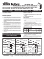
READ AND SAVE THESE INSTRUCTIONS
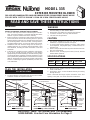
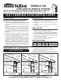
MODEL 335
EXTERIOR MOUNTED BLOWER
FOR USE WITH RANGEMASTER 60000 OR RM60000 SERIES OR 64000 SERIES RANGE HOODS
FOR USE WITH "BEST BY BROAN" K-210A OR K-260A SERIES RANGE HOODS
WARNING
TO REDUCE THE RISK OF FIRE, ELECTRIC SHOCK, OR
INJURY TO PERSONS, OBSERVE THE FOLLOWING:
1. Use this unit only in the manner intended by the manufac-
turer. If you have questions, contact the manufacturer at the
address or phone number listed in the warranty.
2. Before servicing or cleaning unit, switch power off at service
panel and lock the service disconnecting means to prevent
power from being switched on accidentally. When the service
disconnecting means cannot be locked, securely fasten a
prominent warning device, such as a tag, to the service panel.
3. Installation work and electrical wiring must be done by a
qualified person(s) in accordance with all applicable codes
and standards, including fire-rated construction codes and
standards.
4. Sufficient air is needed for proper combustion and exhaust-
ing of gases through the flue (chimney) of fuel burning
equipment to prevent backdrafting. Follow the heating equip-
ment manufacturer's guideline and safety standards such as
those published by the National Fire Protection Association
(NFPA), and the American Society for Heating, Refrigeration
and Air Conditioning Engineers (ASHRAE), and the local
code authorities.
CAUTION
1. For general ventilating use only. Do not use to exhaust
hazardous or explosive material and vapors.
2. To avoid motor bearing damage and noisy and/or unbal-
anced impellers, keep drywall spray, construction dust, etc.
off power unit.
3. Please read specification label on product for further informa-
tion and requirements.
4. Electrical circuit, including speed control, (if used), must be
rated 6 AMPS minimum.
MODEL VOLTS AMPS CFM DUCT SIZE
335 120 3.0 1200 10" DIA.
SPECIFICATIONS
INSTALLER: Leave This Manual With The Homeowner
HOMEOWNER: Use And Care Information On Page 4
MODEL 335
EXTERIOR BLOWER
WALL HOOD
CANOPY
(island canopy
available)
10" ROUND
DUCT
SOFFIT
24" or 27"
18"
ROUGH-IN
PLATE
DUCT
OPENING
COVER PLATE
MODEL
335
EXTERIOR
BLOWER
WALL HOOD
CANOPY
(island canopy
available)
10" ROUND DUCT
SOFFIT
ROUGH-IN
PLATE
24" or 27"
18"
10" ROUND ELBOW
DUCT
OPENING
COVER PLATE
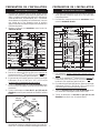
TYPICAL ROOF MOUNTED INSTALLATION
(Vertical discharge)
TYPICAL WALL MOUNTED INSTALLATION
(Vertical discharge - elbow to horizontal)
WARNING
5. When cutting or drilling into wall, or ceiling, do not damage
electrical wiring or other hidden utilities.
6. Ducted fans must always be vented to the outdoors.
7. To reduce risk of fire, use only metal ductwork.
8. This unit must be grounded.
MODEL 335
EXTERIOR
BLOWER
WALL HOOD
CANOPY
(island canopy
available)
10" ROUND DUCT
SOFFIT
ROUGH-IN
PLATE
24" or 27"
18"
DUCT
OPENING
COVER
PLATE
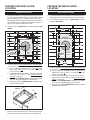
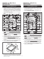
PLAN THE INSTALLATION
1. Locate the blower so the length of the duct run and number
of elbows needed are kept to a minimum.
ALL INSTALLATIONS
TYPICAL WALL MOUNTED INSTALLATION
(Horizontal discharge)
2. Where possible, blower should be centered between wall
studs or roof rafters.
3. Avoid pipes, wires, or other ductwork that may be running
through the wall.
NOTE: Horizontal discharge requires relocation of the duct
opening cover plate. See hood manual for instructions.

2
11" dia.
hole
20½"
11" dia.
hole
1"
ØØ
9
11
/
16
"
20½"
ØØ
15"
9
13
/
16
"
18"
12
11
/
16
"
1¼" dia. hole1¼" dia. hole
Roof Rafter
Roof Rafter
Roof Rafter
REMOVE SHINGLESREMOVE SHINGLES
Roof Rafter
Guide hole
(centered
between rafters)
Guide hole
(centered
between rafters)
12
11
/
16
"
18"
11" dia.
hole
22"
Guide hole
(centered between studs)
22"
29½"29½"
14
11
/
16
"
11
13
/
16"11
13
/
16"
17"
Wall Stud
Wall Stud
11" dia.
hole
17"
1¼" dia. hole1¼" dia. hole
3
"
ØØ
ØØ
REMOVE
SIDING
REMOVE
SIDING
Guide hole
(centered between studs)
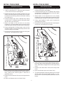
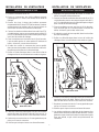
1. Choose a position on the outside wall. Make sure that no
wall studs, pipes or wires run through the opening area.
2. From inside, mark and drill a guide hole centered
between wall studs.
PREPARE THE INSTALLATION
LOCATION
ROOF INSTALLATIONS
22"
2"
7"
29-1/2"
2"
WALL INSTALLATIONS
1. Locate the blower on the rear slope of the roof. Place
it in a location to minimize duct run. The location should
be free of obstacles (T.V. leads, electrical lines, etc.).
If the blower top is level with the roof peak, it will not be
seen from the street. Keep this approximate location in
mind as you work from within the attic.
2. Mark and drill a guide hole centered between roof
rafters.
3. From the outside, use the guide hole as a starting point
to lay out the installation:
A. Use a T-square to measure 9
13
/
16
" to the left of the
guide hole, then up 12
11
/
16
" to locate the top-left
corner of the layout.
B. Starting from the top-left corner, mark the rectangular
cutout (18" W x 20½" H) and remove only the
shingles in this area.
C. Mark an 11" diameter hole centered on the guide
hole. Cut this hole through the roof board(s).
D. Mark and cut a 1¼" diameter hole through the roof
board(s) where shown.
4. For flat roof installations, build a curb that will mount the
blower at a minimum pitch of 2/12. Discharge end of the
blower should be pointed away from prevailing winds.
PREPARE THE INSTALLATION
LOCATION
3. From the outside, use the guide hole as a starting point
to lay out the installation:
A. Use a T-square to measure 11
13
/
16
" to the left of the
guide hole, then up 14
11
/
16
" to locate the top-left
corner of the layout.
B. Starting from the top-left corner, mark the rectan-
gular cutout (22" W x 29½" H) and remove only the
siding in this area.
C. Mark an 11" diameter hole centered on the guide
hole. Cut this hole through the wall board(s).
D. Mark and cut a 1¼" diameter hole through the wall
board(s) where shown.

3
1. Remove the cover and screws.
2. Attach an appropriate U.L. approved cable connector
in the hole at the rear of the wiring box.
3. Remove roofing nails from shingles around the TOP and
SIDES of the cutout area only.Carefully lift the shingles
to allow the back flashing sheet on the blower housing
to fit under them.
4. Center the blower ring in the 11" diameter hole, making
sure that the 1¼" diameter electrical wiring hole aligns
with the hole in the wiring box.
5. Attach the blower to the roof with six (6) screws
provided. It is recommended that the screws be located
inside the blower housing. Drill pilot holes if necessary.
6. Using a good grade of roofing cement, seal all of the
shingles around the housing and flashing sheet as well
as the mounting screw heads.
7. Bring electrical wiring through the hole in the wiring box
and secure it according to local codes.
8. Make the electrical connections with the proper connec-
tor for the type of wiring being used. Connect black to
black, white to blue, and the green or bare wire to
grounding screw.
9. Replace cover and screws. Do not pinch wiring under the
cover.
10. Make sure damper opens and closes freely.
1. Place a large bead of caulk on the back side of the
housing all along the outer edges.
2. Center the blower ring in the 11" diameter hole, making
sure that the 1¼" diameter electrical wiring hole aligns
with the hole in the wiring box.
3. Attach blower to the wall with the six (6) screws
provided. It is recommended that the screws be located
inside the blower housing. Drill pilot holes if necessary.
4. Using a good grade of caulk, seal all around the
mounting screw heads.
5. Bring electrical wiring through the hole in the wiring box
and secure it according to local codes.
INSTALL THE BLOWER
ROOF INSTALLATIONS
INSTALL THE BLOWER
WALL INSTALLATIONS
BLACK
TO
BLACK
120 VAC
LINE
IN
WHITE
TO
BLUE
GROUND
TO
GROUNDING
SCREW
BLACK
TO
BLACK
120 VAC
LINE
IN
WHITE
TO
BLUE
GROUND
TO
GROUNDING
SCREW
6. Make the electrical connections with the proper connec-
tor for the type of wire being used. Connect black to
black, white to blue, and green or bare wire to grounding
screw.
7. Replace cover and screws. Do not pinch wiring under
cover.
8. Make sure damper opens and closes freely.
9. Top and side flanges of the back plate may be covered
with trim strips. Do not block grille opening at bot-
tom with trim. It will adversely affect performance of the
blower.

4 99042798E
USE AND CARE
Disconnect electrical power supply and lock out service
panel before cleaning or servicing this unit.
CLEANING
Remove cover and carefully vacuum blower and inside of
housing. Be careful not to bend or otherwise damage
blower wheel.
MOTOR LUBRICATION
The motor is permanently lubricated. Do not oil or
disassemble motor.
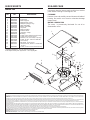
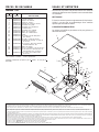
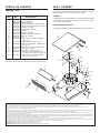
SERVICE PARTS
Model 335
KEY PART
NO. NO. DESCRIPTION
1 98009429 Cover
2 99100532 Foam Seal
3 98009430 Motor Support
4 98009497 Damper Flap (2 req.)
5 99140145 Damper Spring (2 req.)
6 97015528 Grille Assembly
7 99080478 Blower Assembly
8 99271202 Capacitor
9 99271222 Wire Assembly
10 99100530 Terminal Boot
11 99390136 Capacitor Clamp
12 99400079 Bushing
13 99150478 Screw, 8-18 x 3/8 Ph Tr Hd (12 req.)
14 99170269 Screw, M6 x 1.0-16 (4 req.)
15 99250958 Washer, Lock, Int. Tooth, ¼ (5 req.)
16 99150506 Screw, 12-24 x .312 SLT HWH #2
17 99270461 Cord Clamp
18 99260477 Nut, Whiz, ¼-20 (9 req.)
19 99150471 Ground Screw, 10-32 x ½ Slt Hx Hd
(2 req.)
20 99160411 Screw, ¼-20 x ½ Ph Pan Hd (9 req.)
* Standard Hardware - may be purchased locally.
Order replacement parts by Part No. - NOT by Key No.
BROAN-NUTONE ONE YEAR LIMITED WARRANTY
Broan-NuTone warrants to the original consumer purchaser of its products that such products will be free from defects in materials or workmanship for a period of one year from the date of original purchase.
THERE ARE NO OTHER WARRANTIES, EXPRESS OR IMPLIED, INCLUDING, BUT NOT LIMITED TO, IMPLIED WARRANTIES OF MERCHANTABILITY OR FITNESS FOR A PARTICULAR
PURPOSE.
During this one-year period, Broan-NuTone will, at its option, repair or replace, without charge, any product or part which is found to be defective under normal use and service.
THIS WARRANTY DOES NOT EXTEND TO FLUORESCENT LAMP STARTERS AND TUBES. This warranty does not cover (a) normal maintenance and service or (b) any products or parts which have
been subject to misuse, negligence, accident, improper maintenance or repair (other than by Broan-NuTone), faulty installation or installation contrary to recommended installation instructions.
The duration of any implied warranty is limited to the one-year period as specified for the express warranty. Some states do not allow limitation on how long an implied warranty lasts, so the above limitation
may not apply to you.
BROAN-NUTONE’S OBLIGATION TO REPAIR OR REPLACE, AT BROAN-NUTONE’S OPTION, SHALL BE THE PURCHASER’S SOLE AND EXCLUSIVE REMEDY UNDER THIS WARRANTY.
BROAN-NUTONE SHALL NOT BE LIABLE FOR INCIDENTAL, CONSEQUENTIAL OR SPECIAL DAMAGES ARISING OUT OF OR IN CONNECTION WITH PRODUCT USE OR PERFORMANCE. Some
states do not allow the exclusion or limitation of incidental or consequential damages, so the above limitation or exclusion may not apply to you.
This warranty gives you specific legal rights, and you may also have other rights, which vary from state to state. This warranty supersedes all prior warranties.
To qualify for warranty service, you must (a) notify Broan-NuTone at the address or telephone number stated below, (b) give the model number and part identification and (c) describe the nature of any defect
in the product or part. At the time of requesting warranty service, you must present evidence of the original purchase date.
Broan-NuTone LLC, 926 West State Street, Hartford, WI 53027 (1-800-637-1453)
NuTone, Inc., 4820 Red Bank Road, Cincinnati, OH 45227 (1-800-543-8687)
Broan-NuTone Canada, Inc., 1140 Tristar Drive, Mississauga, Ontario L5T 1H9 (1-888-882-7626)
1
2
3
4
5
6
7
8
10
11
12
13
13
14
15
16
17
18
18
19
15
20
9

5
MODEL
335
EXTERIOR
BLOWER
WALL HOOD
CANOPY
(island canopy
available)
10" ROUND DUCT
SOFFIT
ROUGH-IN
PLATE
24" or 27"
18"
10" ROUND ELBOW
DISCHARGE
COVER
PLATE
MODEL 335
EXTERIOR
BLOWER
WALL HOOD
CANOPY
(island canopy
available)
10" ROUND DUCT
SOFFIT
ROUGH-IN
PLATE
24" or 27"
18"
DUCT
OPENING
COVER
PLATE
OBSERVEZ LES DIRECTIVES CI-DESSOUS DE MANIÈRE À RÉDUI-
RE LES RISQUES D’INCENDIE, DE CHOC ÉLECTRIQUE OU DE
BLESSURES CORPORELLES.
1. N’utilisez cet appareil que de la manière prévue par le fabricant. Si
vous avez des questions, contactez le fabricant ou le distributeur.
2. Avant de procéder à la réparation ou à l’entretien de l’appareil, coupez
l’alimentation du panneau d’entrée d’électricité et verrouillez le
dispositif de sectionnement de manière à empêcher que le courant
ne soit accidentellement rétabli. S’il est impossible de verrouiller le
dispositif de sectionnement, fixez solidement un système de protec-
tion bien en vue, par exemple une étiquette, au panneau d’entrée
d’électricité.
3. La pose de l’appareil et les travaux d’électricité doivent être effectués
par des personnes qualifiées en respectant la réglementation en
vigueur, notamment les codes et normes de la construction ayant
trait à la résistance au feu.
4. Pour éviter les refoulements, l’apport d’air doit être suffisant de
manière à brûler et à évacuer, par le conduit de fumée (cheminée),
les gaz produits par les appareils à combustibles. Respectez les
directives du fabricant de l’appareil de chauffage et les normes de
sécurité, notamment celles publiées par la National Fire Protection
Association (NFPA), la American Society for Heating, les Refrige-
ration and Air Conditioning Engineers (ASHRAE) et les codes des
autorités locales.
5. Veillez à ne pas endommager le câblage électrique ou d’autres
équipements non apparents lors de la découpe ou du perçage du mur
ou du plafond.
VEUILLEZ LIRE CES DIRECTIVES ET LES CONSERVER
1. Cet appareil ne doit servir qu’à la ventilation générale. Ne l’utilisez pas
pour éliminer des matières ni des vapeurs dangereuses ou explo-
sives.
2. Pour éviter d’endommager les roulements de moteur, de déséqui-
librer les pales ou de les rendre bruyantes, débarrassez l’appareil
de la poussière de plâtre, de construction, etc.
3. Veuillez lire l’étiquette de spécifications du produit pour obtenir plus
de renseignements, notamment sur les normes.
4. Le circuit électrique, y compris la commande de régime (le cas
échéant), doit avoir au minimum une puissance nominale de 6
ampères.
TOUS LES TYPES DE POSE
DIMENSION
MODÈLE VOLTS AMPÈRES PCM DU CONDUIT
335 120 3.0 1200 DIAMÈTRE
DE 25,4 cm
(10 po)
SPÉCIFICATIONS
POSE TYPE - VENTILATEUR MONTÉ SUR LE TOIT
(Décharge verticale)
POSE TYPE - VENTILATEUR MONTÉ SUR LE
MUR
(Décharge verticale - coude à horizontal)
AVERTISSEMENTAVERTISSEMENT
6. Les ventilateurs canalisés doivent toujours être ventilés à l’air libre.
7. Pour réduire les risques d’incendie, utilisez seulement des conduits
en métal.
8. Cet appareil doit être mis à la terre.
ATTENTION
POUR L'USAGE AVEC HOTTES DE RANGEMASTER 60000 OU SÉRIE RM60000 OU SÉRIE 64000
POUR L'USAGE AVEC HOTTES DE "BEST BY BROAN" SÉRIE K-210A OU K-260A
MODÈLE 335
VENTILATEUR MONTÉ À L’EXTÉRIEUR
MODEL 335
EXTERIOR BLOWER
WALL HOOD
CANOPY
(island canopy
available)
10" ROUND
DUCT
SOFFIT
24" or 27"
18"
ROUGH-IN
PLATE
DISCHARGE
COVER
PLATE
MODÈLE 335
VENTILATEUR EXTÉRIEUR
PLAQUE
DU
VENTILA-
TEUR
61 ou 68,6 cm
(24 ou 27 po)
45,7 cm
(18 po)
SOFFITTE
CONDUIT ROND
DE 25,4 cm (10 po)
VERRIÈRE
HOTTE DE MUR
(verrière de île
disponible)
PLAQUE DU
DÉCHARGE
PLANIFICATION DE L'INSTALLATION
1. L’emplacement de pose du ventilateur doit être choisi de manière à
réduire le plus possible l’utilisation de conduits et de coudes.
TOUTES LES INSTALLATIONS
2. Lorsque cela est envisageable, le ventilateur doit être centré entre
les poteaux muraux ou les chevrons du toit.
3. Évitez les tuyaux, les fils ou autres conduits qui peuvent passer dans
les murs.
NOTA: Décharge horizontal exige la relocalisation de la plaque du
décharge. Voir le manuel de hotte pour des instructions.
POSE TYPE - VENTILATEUR MONTÉ SUR LE MUR
(Décharge horizontal)
PLAQUE
DU
VENTILA-
TEUR
61 ou 68,6 cm
(24 ou 27 po)
45,7 cm (18 po)
SOFFITTE
VERRIÈRE
HOTTE DE MUR
(verrière de île
disponible)
PLAQUE DU
DÉCHARGE
MODÈLE
335
VENTILA-
TEUR
EXTÉRIEUR
CONDUIT ROND
DE 25,4 cm (10 po)
COUDE DE
25,4 cm (10 po)
VERRIÈRE
HOTTE DE MUR
(verrière de île
disponible)
SOFFITTE
61 ou 68,6 cm
(24 ou 27 po)
45,7 cm
(18 po)
CONDUIT ROND
DE 25,4 cm (10 po)
PLAQUE DU
VENTILATEUR
MODÈLE
335 VENTI-
LATEUR
EXTÉRIEUR
PLAQUE
DU
DÉCHARGE
INSTALLATEUR : Veuillez laisser ce manuel au propriétaire
PROPRIÉTAIRE : La page 8 contient des renseignements portant sur l’utilisation et l’entretien

6
20½"
1"
2,5
cm
ØØ
20½"
52,1 cm
ØØ
18"
38,1 cm
18"
12
11
/
16
"
18"
45,7 cm
15 po
38,1 cm
12
11
/
16
po
32,2 cm
20½ po
52,1 cm
1po
2,5
cm
18 po
45,7 cm
Avant-trou
(centré entre les
chevrons)
ENLEVER LES
BARDEAUX
Trou de
11 po (27,9 cm)
Chevron
Trou de
1¼ po 3,2 cm
de diá.
9
13
/
16
po
24,9 cm
Trou de
1¼ po 3,2 cm
de diá.
ENLEVER LES
BARDEAUX
Trou de
11 po (27,9 cm)
12
11
/
16
po
32,2 cm
9
13
/
16
po
24,9 cm
Chevron
ChevronChevron
Avant-trou
(centré entre les
chevrons)
22 po
55,9 cm
Chevron
3 po
7,6
cm
ØØ
ØØ
29½ po
74,9 cm
17 po
43,2 cm
14
11
/
16
po
37,3 cm
11
13
/
16
po
30 cm
ENLEVER
LES
BARDEAUX
Trou de 1¼ po
(3,2 cm)
Avant-trou
(centré entre les c entre les chevrons)
Trou de
11 po
(27,9 cm)
14
11
/
16
po
37,3 cm
17 po
43,2 cm
29½ po
74,9 cm
Chevron
Avant-trou
(centré entre les chevrons)
Trou de 1¼ po
(3,2 cm)
ENLEVER
LES
BARDEAUX
Trou de
11 po
(27,9 cm)
1. Choisissez l’emplacement sur un mur extérior. Assurez-
vous qu’aucun montant, tuyau ou fil ne court dans
l’ouverture prévue.
2. De l’intérieur, marquez et percez un avant-trou centré
entre les montants du mur.
1. Positionez le ventilateur sur la pente arrière du toit.
Placez-le de manière à minimiser la longueur des con-
duits. L’emplacement doit être dépourvu d’obstacles
(câble de télévision, fils électriques, etc.). si le dessus
du ventilateur est à égalité avec le faîte du toit, il ne sera
pas visible de la rue. Rappelez-vous la position
approzimative du ventilateur lorsque vous travaillerez à
l’intérieur du grenier.
2. Marquez et percez un avant-trou centré entre les
chevrons du toit.
INSTALLATIONS SUR LE TOIT
PRÉPARATION DE L’INSTALLATION PRÉPARATION DE L’INSTALLATION
3. De l’extérieur, utilisez l’avant-trou comme point de départ
pour tracer le plan d’installation:
A. Avec un té, mesurez 9
13
/16 po (24,9 cm) à gauche de
l’avant-trou, puis 12
12
/16 po (32,2 cm) vers le haut pour
localiser le coin supérieur gauche du plan.
B. En partant du coin supérior gauche, tracez le rectangle
à découper (18 po L x 20½ po H - 45,7 x 52,1 cm) et
n’enlevez que les bardeaux de cette surface.
C. Tracez un trou de 11 po (27,9 cm) de diamètre centré
sur l’avant-trou. Découpez ce trou dans le panneau de la
couverture.
D. Tracez et découpez un trou de 1¼ po (3,2 cm) de
diamètre à travers le panneau de la couverture à l’endroit
illustré.
INSTALLATIONS SUR LE MUR
3. De l’exterieur, utilisez l’avant-trou comme point de
départ pour tacer le plan d’installation:
A. Avec un té, mesurez 11
13
/16 po (30 cm) à gauche de
l’avant-trou, puis 14
11
/16 po (37,3 cm) vers le haut pour
localiser le coin supérieur gauche du plan.
B. En partant du coin supérieur gauche, tracez le rectangle
à découper (22 po L x 29½ po H - 55,9 x 74,9 cm) et
n’enlevez que le parement de cette surface.
C. Tacez un trou de 11 po (27,9 cm) de diamètre centré
sur l’avant-trou. Découpez ce trou cans le mur.
D. Tracez et découpez un trou de 1¼ po (3,2 cm) de
diamètre à travers le mur à l’endroit illustré.
2 po
(5,1 cm)
7 po
(17,8 cm)
2 po
(5,1 cm)
29½ po
(74,9 cm)
22 po
(55,9 cm)
4. Pour une installation sur un toit plat, bâtissez un cadre qui
permettra de monter le ventilateur selon une pente d’au
moins 2/12. La sortie du ventilateur sera dirigée vers le bas.

7
INSTALLATION DU VENTILATEUR INSTALLATION DU VENTILATEUR
NOIR AVEC NOIR
ARRIVÉE
120 VCA
BLANC
AVEC
BLEU
FIL DE
TERRE SUR
VIS DE MISE
À LA TERRE
NOIR AVEC NOIR
ARRIVÉE
120 VCA
BLANC
AVEC
BLEU
FIL DE
TERRE SUR
VIS DE MISE
À LA TERRE
1. Enlevez le couvercle et les vis.
2. Fixez un connecteur de câble adéquat portant
l’homologation U.L. dans le trou arrière de las boîte de
câblage.
3. Enlevez les clous à toiture des bardiaux entourant
uniquement le HAUT et les CÔTÉS de l’ouverture. Soulevez
soigneusement les bardiaux afin de pouvoir glisser le
solin arrière du boîtier du ventilateur en dessous.
4. Centrez l’anniau de ventilateur dans le trou de 11 po (27,9
cm) de diamètre, tout en vous assurant que le trou de 1¼
po (3,2 cm) de diamètre pour le câble électrique est aligné
avec celui de la boîte de câblage.
5. Fixez le ventilateur sur le toit avec les six (6) vis fournies.
Il est conseillé que les vis soient posées à l’intérieur du
boîtier. Au besoin, percez des avant-trous.
6. À l’aide d’un mastic à couverture de bonne qualité,
étanchez tous les bardeaux autour du boîtier et du solin,
de même que les têtes de vis d’assemblage.
7. Enfilez un câble électrique dans le trou de la boîte de
câblage et fixez-le conformément aux codes en vigueur.
1. Appliquez une grosse bande de mastic à l’arrière du
boîtier le long des arêtes extétieures.
2. Centrez l’anneau du ventilateur dans le trou de 11 po (27,9
cm) de diamètre, tout en vous assurant que le trou de 1¼
po (3,2 cm) de diamètre pour le câble électrique est aligné
avec celui de la boîte de câblage.
3. Fixez le ventilateur au mur avec les six (6) vis fournies.
Il est conseillé que les vis soient posées à l’intérieur du
boîtier. Au besoin, percez des avant-trous.
4. À l’aide d’un mastic de bonne qualité, étanchez les têtes
de vis d’assemblage.
5. Enfilez un câble électrique dans le trou de la boîte de
câblage et fixez-le conformément aux codes en vigueur.
8. Faites les connexions électriques avec les connecteurs
appropriés selon le fil utilisé. Reliez le fil noir au noir, le
blanc au blanc et le fil vert ou nu à la vis de mise à la terre.
9. Replacez le couvercle et les vis. Prenez garde de ne pas
pincer un fil sous le couvercle.
10. Vérifiez que le clapet s’ouvre et se ferme librement.
6. Faites les connexions électriques avec les connecteurs
appropriés selon le fil utilisé. Reliez le fil noir au noir, le
blanc au bleu et le fil vert ou nu à la vis de mise à la terre.
7. Replacez le couvercle et les vis. Prenez garde de ne pas
pincer un fil sous le couvercle.
8. Vérifiez que le clapet s’ouvre et se ferme librement.
9. Les brides supérieures et latérales de la plaque arrière
peuvent être couvertes par des bandes de finition. Prenez
garde de ne pas obstruer le bas de l’ouverture de la grille
avec une bande, ce qui nuirait aux performances du
ventilateur.
INSTALLATIONS SUR LE TOIT
INSTALLATIONS SUR LE MUR

8 99042798E
USAGE ET ENTRETIEN
Débrancher le courant et le panneau de service avant de
nettoyer ou d’effectuer une réparation ou un entretien dans
ce ventilateur.
NETTOYAGE
Enlever le couvercle passer soigneusement à l’aspirateur.
Veillez à ne pas plier ou endommager d’une manière
quelconque la roue du ventilator.
LUBRIFICATION DU MOTEUR
Le moteur est lubrifié en permanence. Ne pas graisser ni
démonter le moteur.
PIÈCES DE RECHANGE
Modèle 335
N
O
N
O
REPÈRE PIÈCE DESCRIPTION
1 98009429 Couvercle
2 99100532 Joint de mousse
3 98009430 Support de moteur
4 98009497 Clapet (2 néces.)
5 99140145 Ressort de clapet (2 néces.)
6 97015528 Ensemble du grille
7 99080478 Ensemble du ventilateur
8 99271202 Condensateur
9 99271222 Ensemble de câblage
10 99100530 Borne de connexion
11 99390136 Bride de condensateur
12 99400079 Palier
13 99150478 Vis, 8-18 x 3/8 Ph tête plate
(12 néces.)
14 99170269 Vis, M6 x 1.0-16 (4 néces.)
15 99250958 Rondelle de blocage à crans,¼
(5 néces.)
16 99150506 Vis, 12-24 x .312 Hex. fendue
autotaraudeause #2
17 99270461 Bride de cordon
18 99260477 Écrou à rondelle, ¼-20 (9 néces.)
19 99150471 Vis de mise à la terre,10-32 x ½
Tête fendue hex. (2 néces.)
20 99160411 Vis, ¼-20 x ½ Ph tête ronde
(9 néces.)
* Quincaillerie ordinaire - vendu séparément.
Veuilllez commander les pièces par N
O
PIÈCE - et non par N
O
REPÈRE.
GARANTIE LIMITÉE D’UN AN DE BROAN-NUTONE
Broan-NuTone garantit à l’acheteur consommateur original de ses produits qu’ils sont exempts de vice de matériaux ou de fabrication pour une période d’un an à compter de la date d’achat original. IL N’Y A PAS D’AUTRES GARANTIES,
EXPRIMÉES OU IMPLICITES, INCLUANT MAIS NON LIMITÉES AUX GARANTIES IMPLICITES DE QUALITÉ MARCHANDE ET DE CONVENANCE DANS UN BUT PARTICULIER.
Durant cette période d’un an, Broan-NuTone, à sa discrétion, réparera ou remplacera gratuitement tout produit ou pièce qui s’avèrera défectueux et ayant été utilisé normalement et d’une manière non abusive.
CETTE GARANTIE NE COUVRE PAS LES STARTERS DE TUBES FLUORESCENTS NI LES TUBES FLUORESCENTS. Cette garantie ne couvre pas (a) l’entretien et le service normal ou (b) tout produit ou pièce endommagé à la suite d’un
mauvais usage, d’une négligence, d’un accident, d’un entretien inadéquat ou d’une réparation (autre que par Broan-NuTone), d’une mauvaise installation ou d’une installation non conforme au mode d’installation recommandé.
La durée de toute garantie implicite est limitée à une période d’un an tel que spécifié pour la garantie exprimée. Certains États ou provinces ne permettent pas de limitation de la durée d’une garantie implicite. Cette condition ne s’applique
donc peut-être pas dans votre cas.
L’ENGAGEMENT DE BROAN-NUTONE À RÉPARER OU À REMPLACER, AU CHOIX DE BROAN-NUTONE, SERA LA SEULE OBLIGATION EXCLUSIVE SOUS CETTE GARANTIE. BROAN-NUTONE NE SE TIENDRA PAS RESPONSABLE DES
DOMMAGES DIRECTS, INDIRECTS OU SPÉCIAUX AYANT UN LIEN DIRECT OU INDIRECT AVEC L’UTILISATION OU LA PERFORMANCE DE SES PRODUITS. Certains États ou provinces ne permettent pas l’exclusion ou la limitation de
dommages directs ou indirects. Cette condition ne s’applique donc peut-être pas dans votre cas.
Cette garantie vous donne des droits spécifiques et il se peut que vous ayez d’autres droits qui varient d’une province à l’autre ou d’un État à l’autre. Cette garantie annule toutes les garanties précédentes.
Pour le service sous garantie, vous devez (a) aviser Broan-NuTone à l’adresse ou le numéro ci-dessous, (b) donner le numéro ou le modèle et l’identification de la pièce et (c) décrire la nature de tout défaut dans le produit ou la pièce. Au
moment de la demande de service sous garantie, vous devez présenter une preuve de la date d’achat original du produit en question.
Aux États-Unis, contactez: Broan-NuTone LLC, 926 West State Street, Hartford, WI 53027 (1-800-637-1453)
Aux États-Unis, contactez: NuTone, Inc., 4820 Red Bank Road, Cincinnati, Ohio 45227 (1-800-543-8687)
Au Canada, contactez: Broan-NuTone Canada, Inc., 1140 Tristar Drive, Mississauga, Ontario, L5T 1H9 (1-888-882-7626)
1
2
3
4
5
6
7
8
10
11
12
13
13
14
15
16
17
18
18
19
15
20
9

9
MODEL
335
EXTERIOR
BLOWER
WALL HOOD
CANOPY
(island canopy
available)
10" ROUND DUCT
SOFFIT
ROUGH-IN
PLATE
24" or 27"
18"
10" ROUND ELBOW
DISCHARGE
COVER
PLATE
MODEL 335
EXTERIOR
BLOWER
WALL HOOD
CANOPY
(island canopy
available)
10" ROUND DUCT
SOFFIT
ROUGH-IN
PLATE
24" or 27"
18"
DUCT
OPENING
COVER
PLATE
TOUS LES TYPES DE POSE
MODEL 335
EXTERIOR BLOWER
WALL HOOD
CANOPY
(island canopy
available)
10" ROUND
DUCT
SOFFIT
24" or 27"
18"
ROUGH-IN
PLATE
DISCHARGE
COVER
PLATE
MODELO 335
VENTILADOR EXTERIOR
PLACA
DE
VENTI-
LADOR
61 a 68,6 cm
(24 a 27 po)
45,7 cm
(18 po)
PLAFÓN
CONDUCTO
REDONDO
DE 25,4 cm
(10 po)
PLACA DE
VENTI-
LADOR
61 a 68,6 cm
(24 a 27 po)
45,7 cm (18 po)
PLAFÓN
PLACA DE
DESCARGA
MODELO
335
VENTILA-
DOR
EXTERIOR
CONDUCTO
REDONDO
DE 25,4 cm (10 po)
CODO DE
25,4 cm (10 po)
PLAFÓN
61 a 68,6 cm
(24 a 27 po)
45,7 cm
(18 po)
CONDUCTO
REDONDO
DE 25,4 cm (10 po)
PLACA DE
VENTILADOR
MODELO
335
VENTILADOR
EXTERIOR
PLACA
DE
DÉSCARGA
LEA Y CONSERVE ESTAS INSTRUCCIONES
MODELO 335
VENTILADOR DE MONTOJE EXTERIOR
PARA EL USO CON CAMPANAS DE RANGEMASTER 60000 O SERIE RM60000 O SERIE 64000
PARA EL USO CON CAMPANAS DE "BEST BY BROAN" SERIE K-210A O K-260A
ADVERTNECIA
Para reducir el riesgo de incendio, descarga eléctrica, o
lesiones a personas, cumpla los siguientes puntos:
1. Solamente use esta unidad de la manera propuesta por el
fabricante. Si tiene alguna pregunta, póngase en contacto
con el fabricante en la dirección o teléfono anotados en la
garantía.
2. Antes de limpiar o de poner en servicio la unidad, apague el
interruptor en el panel de servicio, y asegure el panel de
servicio para evitar que se encienda accidentalmente.
Cuando el dispositivo para desconectar el servicio eléctrico
no puede ser cerrado con algún tipo de traba, sujete
fuertemente al panel de servicio, una etiqueta de advertencia
prominente.
3. El trabajo de instalación y el alambrado eléctrico deben
llevarse a cabo por personal calificado de acuerdo con todos
los códigos y las normas aplicables, incluyendo los códigos
y normas de construcción contra incendios.
4. Se requiere una cantidad de aire suficiente para la combustión
y escape de gases por la chimenea del equipo de quemado
de combustible para evitar salirse de las especificaciones y
estándares de seguridad del fabricante, tales como los
publicados por la Asociación nacional de protección contra
incendios (NFPA por sus siglas en Inglés), y la Sociedad
americana de ingenieros de calefacción, refrigeración y aire
acondicionado (ASHRAE por sus siglas en Inglés), y los
códigos de las autoridades locales.
PRECAUCION
1. Sólo para uso de ventilación general. No se use para extraer
materiales o vapores peligrosos o explosivos.
2. Para evitar daños al cojinete del motor y/o impulsores
ruidosos o desequilibrados, mantenga la fuente de potencia
lejos de rocíos de pared seca, de polvo de construcción, etc.
3. Lea la etiqueta de especificaciones en el producto para
mayor información y requisitos.
4. El circuito, incluyendo el control de la velocidad (si lo usa),
debe tener capacidad de 6 AMPS mínimo.
MODELO VOLTIOS AMPS CFM TAMAÑO DUCTO
335 120 3.0 1200 25,4 cm de dia. (10 po)
SPECIFICACIONES
INSTALACIÓN TÍPICA DE MONTAJE EN LA PARED
(Descarga vertical - codo a horizontal)
ADVERTENCIA
5. Cuande corte o taladre en una pared o techo, no dañe los
cables eléctricos ni otras instalaciones ocultas.
6. Los ventiladores con ductos siempre deben de ventilar hacia
el exterior.
7. Para reducir el riesgo de incendio, use solamente conductos
de metal.
8. Esta unidad se debe conectar a tierra.
PLANEAMIENTO DE LA INSTALACION
1. Ubique el ventilador de manera que la longitud del ducto
y el número de codos se reduzcan al mínimo.
TODAS LAS INSTALACIONES
2. Cuando sea posible el ventilador deberá centrarse entre
los montantes de la pared o las vigas del techo.
3. Evite tubos, cables u otros ductos que puedan estar
tendidos a lo largo de la pared.
NOTA: Descarga horizontal requiere la relocalización de la placa
de déscarga. Vea el manual de la capilla para las instrucciones.
INSTALACIÓN TÍPICA DE MONTAJE EN LA PARED
(Descarga horizontal)
INSTALACIÓN TÍPICA DE MONTAJE EN EL
TECHO
(Descarga vertical)
TOLDO DE LA
CAMPANA DE PARED
(pabellón de la isla
disponible)
PLACA DE
DESCARGA
TOLDO DE LA
CAMPANA DE PARED
(pabellón de la isla
disponible)
TOLDO DE LA
CAMPANA DE PARED
(pabellón de la isla
disponible)
INSTALADOR: Deje este manual con el usuario.
USUARIO: Uso y información sobre el cuidado en la página 12.

10
29½"
74,9 cm
74,9 cm
Montante de la pared
Orificio
Orificio
de 11 po
de 11 po
(27,9 cm)
(27,9 cm)
de di
de di
á.
Orificio de 1
Orificio de 1
¼ po
po
(3,2 cm) de di
(3,2 cm) de di
á.
3
po
7,6
cm
ØØ
ØØ
QUITE
EL
EL
FORRO
FORRO
Orificio gu
Orificio gu
ía
(centrado entre los
(centrado entre los
montantes)
montantes)
29½ po
po
74,9 cm
74,9 cm
17 po
17 po
43,2 cm
43,2 cm
1
4
14
11
/
16
16
po
po
37,3 cm
37,3 cm
11
13
13
/
/
16
16
po
30 cm
30 cm
QUITE
EL
FORRO
Orificio de 1¼ po
(3,2 cm) de diá.
Orificio guía
(centrado entre los
montantes)
Orificio
de 11 po
(27,9 cm)
de diá.
Montante de la pared
1
4
11
/
16
po
37,3 cm
17 po
43,2 cm
29½ po
74,9 cm
22 po
22 po
55,9 cm
55,9 cm
22 po
55,9 cm
11
13
/
16
po
30 cm
20½"
Orificio de
11 po (27,9 cm)
11 po (27,9 cm)
ØØ
20½"
52,1 cm
52,1 cm
ØØ
18"
18"
38,1 cm
38,1 cm
Orificio de
Orificio de
1¼ po (3,2 cm)
po (3,2 cm)
de di
de di
á.
Viga del techo
Viga del techo
QUITE LAS TEJAS
QUITE LAS TEJAS
Orificio gu
Orificio gu
ía
(centrado entre
(centrado entre
las vigas)
las vigas)
15 po
38,1 cm
20½ po
52,1 cm
Orificio guía
(centrado entre
las vigas)
QUITE LAS TEJAS
de diá.de diá.
Viga del techo
Viga del techo
Viga del techo
Viga del techo
9
13
13
/
16
16
po
po
24,9 cm
24,9 cm
12
12
11
/
16
16
po
po
32,2 cm
32,2 cm
12
11
/
16
po
32,2 cm
1 po
1 po
2,5
2,5
cm
1 po
2,5
cm
18 po
18 po
45,7 cm
45,7 cm
18 po
45,7 cm
9
13
/
16
po
24,9 cm
Orificio de
1¼ po (3,2 cm)
de diá.
Orificio de
11 po (27,9 cm)
PREPARE EL ÁREA DE LA
INSTALACION
INSTALACIONES DE TECHO
22 po
55,9 cm
2 po
5,1 cm
7 po
17,8 cm
29½ po
74,9 cm
2 po
5,1 cm
INSTALACIONES DE PARED
PREPARE EL ÁREA DE LA
INSTALACION
1. Ubique el ventilador en la pendiente posterior del techo.
Colóquelo en un área en la cual minimice la longitud del
tramo de conductos. Esta área debe estar libre de obstáculos
(cables de T.V., cables eléctricos, etc.). Si la parte superior
del ventilador está al ras del pico del techo, no se verá desde
la calle. Mantenga en mente esta ubicación aproximada
mientras trabaja desde el ático.
2. Marque y haga un orificio guía centrado entre las vigas del
techo.
3. Desde el exterior,
utilice el orificio guía como el punto de
partida del diagrama de la instalación:
A. Use una escuadra en T para medir 9-13/16 po (24,9 cm) a
la
izquierda del orificio guía, luego hacia arriba 12-11/16 po
(32,2 cm) para ubicar la esquina superior izquieerda del
diagrama de instalación.
B. Comenzando desde la esquina superior izquierda, marque
un corte rectangular 18 po (45,7 cm) de ancho x 20½ po (52,1
cm) de alto) y
quite las tejas solamente de esta área.
C. Marque un orificio de 11 po (27,9 cm) de diámentro centrado
en el orificio guía. Haga este orificio a través de la(s) tabla(s)
del techo.
D. Marque un orificio de 1¼ po (3,2 cm) de diámetro a través
de la(s) tabla(s) del techo, como se muestra.
4. Para instalar un ventilador sobre un techo plane, construya
un bastidor para soportar al ventilador, con una pendiente
mínima de 2/12. El extremo de descarga del ventilador debe
apuntar hacia abajo.
1. Seleccione un área en la pared exterior. Asegúrese de que
no haya montantes de la pared, tubería ni cables tendidos
den el área de la abertura.
2. Desde el interior, marque y haga un orificio guía centrado
entre los montantes de la pared.
3. Desde el exterior,
utilice el orificio guía como el punto de
partida del diagrama de la instalación:
A. Use una escuadra en T para medir 11-13/16 po (30 cm) a la
izquierda del orificio guía, luego hacia arriba 14-11/16 po
(37,3 cm) para ubicar la esquina superior izquierda del
diagrama de instalación.
B. Comenzando desde la esquina superior izquierda, marque
un corte rectangular (22 po (55,9 cm) de ancho x 29½ po
(74,9 cm) de alto) y
quite el forro solamente de esta área.
C. Marque un orificio de 11 po (27,9 cm) de diámetro centrado
en el orificio guía. Haga este orificio a través de la pared.
D. Marque un orificio de 1¼ po (3,2 cm) de diámetro a través
de pared, como se muestra.

11
INSTALE DEL VENTILADOR
INSTALACIONES DE TECHO
INSTALE DEL VENTILADOR
INSTALACIONES DE PARED
NEGRO A
NEGRO
LÍNEA DE
ENTRADA
120 VCA
BLANCO
A
AZUL
TIERRA AL
TORNILLO DE
CONEXIÓN
A TIERRA
NEGRO A
NEGRO
LÍNEA DE
ENTRADA
120 VCA
BLANCO
A
AZUL
TIERRA AL
TORNILLO DE
CONEXIÓN
A TIERRA
1. Quite la cubierta y los tornillos.
2. Coloque un conectador de cables apropiado, aprobado por
U.L., en el orificio que se encuentra en la parte posterior de
la caja de conexiones.
3. Quite los clavos solamente de las tejas que se encuentran
en las partes SUPERIOR y LATERALES del área de corte.
Con cuidado levante las tejas para permitir que la hoja
cubrejuntas posterior de la cubierta del ventilador quepa
debajo de ellas.
4. Centre el anillo del ventilador en el orificio de 11” (27,9 cm),
asegurándose de que el orificio del cableado eléctrico, de
1¼” (3,2 cm) de diámetro, quede alineado con el orificio de
las caja de conexiones.
5. Monte el ventilador en el techo con los seis (6) tornillos que
se proporcionan. Se recomienda que se coloquen los
tornillos en el interior de la cubierta del ventilador. Si es
necesario haga orificios piloto.
6. Utilizando un cemento para techo de buena calidad, selle
todas las tejas alrededor de la cubierta y de la hoja cubrejun-
tas, así como alrededor de la cabeza de los tornillos de
montaje.
7. Pase los cables eléctricos a través del orificio del la caja de
conexiones y segúrelos de acuerdo con los códigos locales.
8. Haga las conexiones eléctricas utilizando el conectador
adecuado para el tipo de cables que está usando. Conecte
el negro con el negro, el blanco con el azul y el verde o el
alambre desnudo al tornillo de conexión a tierra.
9. Reemplace las cubiertas y los tornillos. No permita que los
cables queden atrapados debajo de la cubierta.
10. Asegúrese de que el regulador de tiro abra y cierre libremente.
1. Coloque un reborde grande de material de calafateo en el
lado posterior de la cubierta, a lo largo de todos los bordes
externos.
2. Centre el anillo del ventilador en el orificio de 11” (27,9 cm),
asegurándose de que el orificio del cableado eléctrico, de
1¼” (3,2 cm) de diámentro, quede alineado con el orificio de
la caja de conexiones.
3. Monte el ventilador en la pared con los seis (6) tornillos que
se proporcionan. Se recomienda que se coloquen los tornil-
los en el interior de las cubierta del ventilador. Si es necesario
haga orificios piloto.
4. Utilizando material de calafateo de buena calidad, selle
alrededor de la cabeza de los tornillos de montaje.
5. Pase los cables eléctricos a través del orificio de la caja de
conexiones y asegúrelos de acuerdo con los códigos lo-
cales.
6. Haga las conexiones eléctricas utilizando el conectador
adecuado para el tipo de cables que está usando. Conecte
el negro con el negro, el blanco con el azul y el verde o el
alambre desnudo al tornillo de conexión a tierra.
7. Reemplace las cubiertas y los tornillos. No permita que los
cables queden atrapados debajo de la cubierta.
8. Asegúrese de que el regulador de tiro abra y cierre libremente.
9. Las aletas superior y laterales de la placa posterior se
pueden cubrir con tiras de resguardo. No bloquee la parte
inferior de la abertura del enrejado con tira de resguardo, ya
que si lo hace afectará adversamente el rendimiento del
ventilador.

12
99042798E
USO Y CUIDADO
Desconecte la fuerza eléctrica y bloquee el panel de servicio
antes de limpiar o hacer el servicio en la unidad.
LIMPIEZA
Saque la tapa y con cuidado limpie con la aspiradora el ventilador
y el interior de la caja. Tenga cuidado de no torcer o causar daño
a los rodetes del ventilador.
LUBRICACION DEL MOTOR
El motor tiene lubricación permanente. No lo enaceite o desarme.
PARTES DE SERVICIO
Modelo 335
CLAVE PARTE
NO. NO. DESCRIPCION
1 98009429 Cubierta
2 99100532 Sello de espuma
3 98009430 Soporte del motor
4 98009497 Aleta del regulador de tiro (se req. 2)
5 99140145 Resorte del regulador de tiro (se req. 2)
6 97015528
Ensemble de rejilla
7 99080478 Conjunto del ventilador
8 99271202 Capacitor
9 99271222 Conjunto de cables
10 99100530 Manguito aislante del terminal
11 99390136 Pinza del capacitor
12 99400079 Buje
13 99150478 Tornillo, 8-18 x 3/8 cabeza Phillips
(se req. 12)
14 99170269 Tornillo, M6 x 1.0-16 (se req. 4)
15 99250958 Arandela de seguridad, dentada int, ¼
(se req. 5)
16 99150506 Tornillo, 12-24 x .312 SLT HWH #2
17 99270461 Pinza para el cordón
18 99260477 Tuerca Whiz, ¼-20 (se req. 9)
19 99150471 Tornillo de conexión a tierra, 10-32 x
½ cabeza hex. estándar (se req. 2)
20 99160411 Tornillo, ¼-20 x ½ cabeza Phillips
troncocónica (se req. 2)
* Tornillería estandar - Pueden comprarse localmente.
Siempre pida repuestos dando el No. de Parte, No la Clave.
GARANTIA BROAN-NUTONE LIMITADA POR UN AÑO
Broan-NuTone garantiza al consumidor comprador original de sus productos que dichos productos carecerán de defectos en materiales o en mano de obra por un período de un año a partir de la fecha original de compra. NO EXISTEN
OTRAS GARANTIAS, EXPLICITAS O IMPLICITAS, INCLUYENDO, PERO NO LIMITADAS A, GARANTIAS IMPLICITAS DE COMERCIALIZACION O APTITUD PARA UN PROPOSITO PARTICULAR.
Durante el período de un año, y a su propio criterio, Broan-NuTone reparará o reemplazará, sin costo alguno cualquier producto o pieza que se encuentre defectuosa bajo condiciones normales de servicio y uso.
ESTA GARANTIA NO SE APLICA A TUBOS Y ARRANCADORES DE LAMPARAS
FLUORESCENTES. Esta garantía no cubre (a) mantenimiento y servicio normales o (b) cualquier producto o piezas que hayan sido utilizadas de forma errónea, negligente, que hayan causado un accidente, o que hayan sido reparadas
o mantenidas inapropiadamente (por otras compañías que no sean Broan-NuTone), instalación defectuosa, o instalación contraria a las instrucciones de instalación recomendadas.
La duración de cualquier garantía implícita se limita a un período de un año como se especifica en la garantía expresa. Algunos estados no permiten limitaciones en cuanto al tiempo de expiración de una garantía implícita, por lo
que la limitación antes mencionada puede no aplicarse a usted.
LA OBLIGACION DE BROAN-NUTONE DE REPARAR O REEMPLAZAR, SIGUIENDO EL CRITERIO DE BROAN-NUTONE, DEBERA SER EL UNICO Y EXCLUSIVO RECURSO LEGAL DEL COMPRADOR BAJO ESTA GARANTIA. BROAN-
NUTONE NO SERA RESPONSABLE POR DAÑOS INCIDENTALES, CONSIGUIENTES, O POR DAÑOS ESPECIALES QUE SURJAN A RAIZ DEL USO O DESEMPEÑO DEL PRODUCTO. Algunos estados no permiten la exclusión o limitación
de daños incidentales o consiguientes, por lo que la limitación antes mencionada puede no aplicarse a usted.
Esta garantía le proporciona derechos legales específicos, y usted puede también tener otros derechos, los cuales varían de estado a estado. Esta garantía reemplaza todas las garantías anteriores.
Para calificar en la garantía de servicio, usted debe (a) notificar a Broan-NuTone al domicilio o el número de teléfono abajo, (b) dar el número del modelo y la identificación de la pieza, y (c) describir la naturaleza de cualquier defecto
en el producto o pieza. En el momento de solicitar servicio cubierto por la garantía, usted debe de presentar evidencia de la fecha original de compra.
Broan-NuTone LLC, 926 West State Street, Hartford, WI 53027 (1-800-637-1453)
NuTone, Inc., 4820 Red Bank Road, Cincinnati, OH 45227 (1-800-543-8687)
Broan-NuTone Canada, Inc., 1140 Tristar Drive, Mississauga, Ontario L5T 1H9 (1-888-882-7626)
1
2
3
4
5
6
7
8
10
11
12
13
13
14
15
16
17
18
18
19
15
20
9
-
 1
1
-
 2
2
-
 3
3
-
 4
4
-
 5
5
-
 6
6
-
 7
7
-
 8
8
-
 9
9
-
 10
10
-
 11
11
-
 12
12


dans d''autres langues
- English: NuTone 335 User manual
- español: NuTone 335 Manual de usuario
Documents connexes
-
Broan 335 Manuel utilisateur
-
-
Broan 335 Manuel utilisateur
-
Broan-NuTone 335 Manuel utilisateur
-
Broan-NuTone 332H Manuel utilisateur
-
-
NuTone RF-49 Series Manuel utilisateur
-
-
NuTone 9425WHC Installation Instructions Manual
-