
1
ENGLISH
FRANÇAIS
DEUTSCH
ESPAÑOL
ITALIANO
12 M 102
OPERATION AND MAINTENANCE MANUAL
NOTICE D'UTILISATION ET ENTRETIEN
BEDIENUNGSANLEITUNG
MANUAL DE USO Y MANTENIMIENTO
MANUALE D'USO E MANUTENZIONE
PNB-3...
PNEUMATIC BENCH PRESS
PRESSE PNEUMATIQUE D'ETABLI
PNEUMATISCHE TISCHPRESSE
PRENSA NEUMÁTICA DE BANCO
PRESSA PNEUMATICA DA BANCO
ENG
LIS
H
12
M
1
02

2
PNB-3
No.
bar
TIPO
TYPE
MATRICOLA
SERIAL
PRESSIONE ARIA
AIR PRESSURE
PRESSA PNEUMATICA
PNEUMATIC PRESS
Via Serenissima, 9 - 25135 Brescia - Italy
6 ÷ 7
Made in Italy
- Press type
- Presse type
- Presse Typ
- Prensa tipo
- Tipo di pressa
- Year
- Année
- Jahr
- Año
- Anno
1
3 4
- Air pressure
- Pression air
- Luftdruck
- Presión aire
- Pressione aria
- Serial Nr.
- No.de série
- Serien Nr.
- No.de serie
- N
o
Matricola
2
4
3
2
1
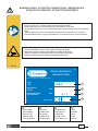
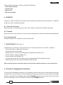
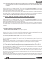
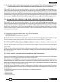
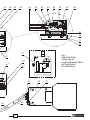
WARNING LABELS - ETIQUETTES SIGNALETIQUES - WARNSCHILDER -
ETIQUETAS DE ATENCION - ETICHETTE D'AVVERTENZA
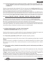
– Before using the press, carefully read the instructions in this manual.
– Avant d'utiliser la presse, lire attentivement les instructions de cette notice.
– Vor dem Bedienen der Presse lesen Sie bitte aufmerksam die Anweisungen in diesem Handbuch
durch.
– Antes de utilizar la prensa, leer atentamente las instrucciones contenidas en este manual.
– Prima di utilizzare la pressa, leggere attentamente le istruzioni contenute in questo manuale.
– When operating, keep hands away from the danger zone.
– Au cours d'utilisation, tenir les mains élognées de la zone de danger.
– Während des benützen nicht mit den Händen in Gefahrbereich langen.
– Durante su utilización, mantenga las manos fuera de la zona de peligro.
– Durante l'utilizzo, mantenere le mani fuori dalla zona di pericolo.
TG0366

3
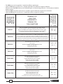
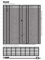
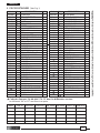
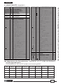
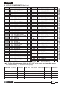
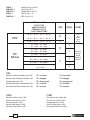
Conductor size
Section câble
Leiterquerschnitt
Sección Conduct.
Sezione condutt.
PNB-3PD
PC bullet and socket connectors
Clips ronds préisolées en PC
Isolierte Rundstecker aus PC
Terminales cilindricos praislados enPC
Connettori ad innesto cilindrico preisolati in PC
PNB-3F/M
PRESS TYPE
PRESSE TYPE
PRESSE TYP
PRENSA TIPO
PRESSA TIPO
PNB-3N1
PNB-3N5
PNB-3NN3
PNB-3NN4
0,25 ÷ 6
(23 - 10)
0,25 ÷ 6
(23 - 10)
0,25 ÷ 10
(23 - 7)
10 ÷ 16
(7 - 5)
1,5 ÷ 10
(15 - 7)
10 ÷ 16
(7 - 5)
0,5 ÷ 2,5
(20 - 13)
PVC, PC and PA6.6 insulated connectors (red, blue, yellow)
Cosses préisolées en PVC, PC et PA6.6 (rouges, bleues, jaunes)
PVC, PC und PA6.6 Isolierte Quetschkabelschuhe (rot, blau, gelb)
Terminales praislados en PVC, PC y PA6.6 (rojos, azul, amarillos)
Connettori preisolati in PVC, PC e PA6.6 (rossi, blu, gialli)
PVC, PC and PA6.6 insulated terminals and END to END (frontal insertion)
Cosses et manchons préisolésen PVC, PC et PA6.6 (insertion frontale)
PVC, PC und PA6.6 Isolierte Quetschkabelschuhe und Verbinder (front positionirung)
Terminales y conectores praislados en PVC, PC y PA6.6 (inserción frontal)
Capicorda e giunti preisolati in PVC, PC, PA6.6 (inserimento frontale)
Un-insulated terminals and lugs
Cosses nus
Nichtisolierte Rohr-und Quetschkabelschuhe
Terminales desnudos
Capicorda non isolati
Un-insulated terminals and lugs
Cosses nus
Nichtisolierte Rohr-und Quetschkabelschuhe
Terminales desnudos
Capicorda non isolati
PA6.6 insulated terminals and lugs
Cosses préisolés en PA6.6
Isolierte Rohrkabelschuhe aus PA6.6
Terminales praislados en PA6.6
Capicorda preisolati in PA6.6
PA6.6 insulated terminals and lugs
Cosses préisolés en PA6.6
Isolierte Rohrkabelschuhe aus PA6.6
Terminales praislados en PA6.6
Capicorda preisolati in PA6.6
PNB-3P..
TERMINAL TYPE
COSSE TYPE
VERBINDER TYP
TERMINAL TIPO
TIPO CONNETTORE
mm
2
(AWG)
– The PNB-3 press can be supplied in 7 models for diff erent applications.
– La presse PNB-3 peut être fournie en 7 modèles répondant aux diff érentes exigences d’emploi.
– Die Presse vom Typ PNB-3 kann je nach Anforderungen und Anwendungsbereich in 7 verschiedenen Modellen
geliefert werden.
– La prensa PNB-3 se puede suministrar en 7 modelos según las diferentes exigencias de utilización.
– La pressa PNB-3 può essere fornita in 7 modelli per le diverse esigenze di impiego.

4
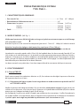
PNEUMATIC BENCH PRESS
TYPE PNB-3...
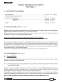
1. GENERAL CHARACTERISTICS
– Air pressure: ..................................................................................................................6 - 7 bar (87 - 100 psi)
– Air feed coupling: ........................................................................................................1/4”
– Dimensions: length .....................................................................................................370 mm (14.57 in.)
width ......................................................................................................130 mm (5.12 in.)
height .....................................................................................................195 mm (7.68 in.)
– Weight: .............................................................................................................................10,3 kg (22.7 lbs)
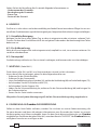
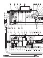
2. INSTRUCTIONS FOR USE (Ref. to Fig. 1)
Check that the machine guard (60) is positioned correctly and the rfi xed screws (37) are fully secured.
Couple the press to a compressed air supply (pressure 6 - 7 bar / 87 - 100 psi) using coupling (22)
situated on the back of the press.
Attention: the maximum pressure must never exceed 7 bar (100 psi).
Make sure that the air system has a fi lter and condensation drain.
Insert the male, quick couplings (43) and (44) of the control pedal into the two female couplings (47)
and (48), positioned on the side of the press. The couplings are of the automatic type: to make the
coupling it is necessary to push the ring of the female coupling whilst the male coupling is inserted;
when the ring is released, the male coupling remains inserted. Disconnection of the couplings is a
reverse of the above instructions.
The two couplings are polarised and it is therefore impossible to couple them incorrectly.
3. OPERATION
3.1) PNB-3P Press
After performing the operations described in 2, it is necessary to adjust the press to suit the range
of terminal to be compressed:
3.1.1) Setting up the press to compress terminals and connectors, pre-insulated with RED or
BLUE PVC or PC
Check the position of the knurled stop (10); it must be completely inserted with the yellow band
invisible, inside with the housing; if this is not the case, press the control pedal (02) and at the same
time push the knurled stop as far as it will go.
To adjust the positioning device refer to § 4. The press is now ready for use; to make the connec-
tion; introduce the terminal, placed on the end of the conductor, into the appropriate aperture in
the head and depress the pedal.
ENGLISH

5
ENGLISH
3.1.2) Setting up the press to compress terminals insulated with YELLOW PVC OR PC and RED
BLUE and YELLOW disconnect terminals partially or fully insulated with PC or PA6.6
Check the position of the knurled stop (10); it must be completely extracted with the yellow band
visible, out of the housing; if this is not the case, press the control pedal (02) and at the same time
pull the knurled stop out as far as it will go.
To adjust the positioning device refer to § 4. The press is now ready for use; to make the connec-
tion; introduce the terminal, placed on the end of the conductor, into the appropriate aperture in
the head and depress the pedal.
3.2) PNB-3PD PNB-3N1 PNB-3NN3 PNB-3N5 PNB-3NN4 PNB-3F/M
Presses
Check the position of the knurled stop (10); it must be completely extracted with the yellow band
visible, out of the housing; if this is not the case, press the control pedal (02) and at the same time
pull the knurled stop out as far as it will go.
The press is now ready for use; to make the connection; introduce the terminal, placed on the end
of the conductor, into the appropriate aperture in the head and depress the pedal.
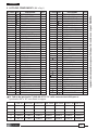
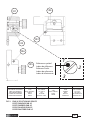
4. INSTRUCTIONS FOR USING THE POSITIONING DEVICE
LOCATED ON THE PNB-3P PRESS (Ref. to Fig. 2, Page 25)
Before using the press it is necessary to make the adjustments to suit the range of terminal to be
compressed, (Refer to TABLE 1 page 26).
4.1) PVC and PC insulated crimp terminals (ring, fork, pin and blade)
Slightly slacken the knob (105) lower stop (104) all the way down and leave the knob slackened.
Introduce the terminal, placed on the end of the conductor, into the appropriate aperture until the
coloured sleeve butts against the stop (104) and depress the pedal.
4.2) Female and male disconnect terminals partially or fully insulated with PC or PA6.6
Slightly slacken knob (105), raise stop (104) to the upper limit and lock in position by tightening
the knob.
Choose the scale position depending on the type of connector to compress by consulting TABLE 1;
slacken the grub screw (106) situated on the upper part of the positioning device turn the reference
symbol to the desired position (refer to table 1) and retighten grub screw (106).
Introduce the terminal, placed on the end of the conductor, into the appropriate aperture, up to
the stop and depress the pedal.

6
ENGLISH
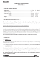
5. PARTS LIST (Ref. to Fig. 1)
Code N° of the items “36-60-66-67-74-75“ in the various versions of the press
Items "66" and "67" are supplied in pairs.
6240140
6631001
2591110
6900659
6900659
36
60
66+67
74
75
PNB-3N1 PNB-3N5 PNB-3NN3 PNB-3NN4 PNB-3F/M PNB-3PD
6240132
6631004
2591120
6900659
6900659
PNB-3P
6580610
6631000
2591110
6900092
6900180
6240134
6631007
2591130
6900659
6900659
6240138
6631008
2591140
6900659
6900659
6240136
6631009
2591150
6900659
6900659
6240145
6631010
2591110
6900092
6900180
Item
The guarantee is void if parts used are not Cembre original spares.
Code N°
Item DESCRIPTION Qty
6780400
01 SILENCER 1
6550050
02 PROTECTED PEDAL 1
6072019
03 COUPLER 2
6000738
04 SHEAT
2
6890050
05 DOUBLE HOSE 1.8 m
6090510 06 SHELL 1
6340058 07 M 5x16 DOWEL 1
6180200 08 M 5 NUT 1
6540110 09 SHAFT 1
6540100 10 KNURLED STOP 1
6760290 11 ø 5x16 SPRING PIN 1
6780205 12
SUPPORT
1
6650205 13 URG 8/1 REGULATOR 1
6900313 14 M 6x18 SCREW 1
6780405 15 SILENCER 1
6895060 16 UKC VALVE 1
6170290 17 M/M CURVE 1
6650200 18 URG 8/5 REGULATOR 1
6525070 19 NIPPLE 1/8”-1/8” MM 1
6641130 20 WASHER 2
6650223 21 REDUCTION 4
6650052 22 COUPLER 1
6650606 25 COUPLER 3
6650604 26 D6 COUPLER 1
6890030 27 PU 4 HOSE 0.7 m
6780400 28 SILENCER 1
6525070 29 NIPPLE 1/8”-1/8” MM 1
6650604 30 D6 COUPLER 1
6580120 31 PLATE 1
6523014 32 SPRING 1
6740120 33 7/32” BALL 1
6900059 34 M 4x8 SCREW 6
6640090 35 M 4 WASHER 6
36 COMPL. POSITIONG DEVICE 1
6900180 37 M 4x10 SCREW 2
6700140 38 CIRCLIP 10
6620600 39 RAM 1
Code N°
Item DESCRIPTION
6560035 40 CYLINDER PIN 1
6700240 41 CIRCLIP ø 18 2
6780210 42 RAM SUPPORT 1
6650066
43 MALE COUPLER 1
6650062
44MALE COUPLER 1
6232080 45 METAL LABEL TG 0280 1
6650121 46 RIVET ø 2,5x3,5 4
6650064 47 FEMALE COUPLER 1
6650058 48 FEMALE COUPLER 1
6180300 49 M 8 NUT 2
6640195 50 M 8 WASHER 2
6900345 51 M 8x16 SCREW 2
6490050 52 HANDLE 1
6650056 53
UNION
1
6900025 54 M 3x8 SCREW 3
6180170 55 M 3 NUT 3
6480800 56 GAUGE 1
6170031 57 U BOLT 1
6560030 58 PIVOT PIN 1
6700060 59 CIRCLIP 2
60 GUARD 1
6560050 61 PIN 5
6440180 62 LINK 1
6440170 63 LINK 2
6340078 64 M 6x35 DOWEL 1
6180265 65 M 6 NUT 1
66 MOBILE JAW 1
67 FIXED JAW 1
6550110 68 SUPPORT 1
6760362 69 ø 6x32 CYLINDRICAL PIN 1
6640195 70 WASHER 4
6900345 71 M 8x16 SCREW 4
6090520 72 BASE 1
6232166 73 LABEL (TG 0366) 1
74 SCREW 2
75 SCREW 1
6550100
COMPLETE PEDAL
Qty

7
ENGLISH
When ordering spare parts always specify the following:
- code number of item.
- name of item.
- type of tool.
- tool serial number.
6. WARNING
The press is robust and does not require special attention; to obtain correct operation it is suffi cient
to observe a few simple precautions:
6.1) Accurate cleaning
After each day’s use clean the press with a clean cloth, to remove dust and dirt particles.
6.2) Storage
When not in use, store the press in a clean, dry area and protect it from dust and accidental demage.
6.3) Control pedal
The fl exible pipes must not be twisted or constricted.
7. MAINTENANCE (Ref. to Fig. 1)
Lubricate the six pivot pins (58) and (61) every 12 months, which ever is earliest, as follows:
– Disconnect the air supply from the press;
– Disconnect the control pedal;
– Remove the six screws (34) holding the housing (06) to the base (72);
– Unscrew the air supply coupling (22);
– Unscrew the knurled knob (10);
– Lift and remove the housing and remove the guard (60), lubricate the pivot pins;
– Refi t the guard, the housing, the coupling and the knob.
After each maintenance operation always check that the machine guards are correctly position.
8. RETURN TO Cembre FOR OVERHAUL
In the case of a breakdown contact our Area Agent who will advise you on the problem and give
you the necessary instructions on how to dispatch the tool to our nearest service Centre; if possible,
attach a copy of the Test Certifi cate supplied by Cembre together with the tool or fi ll in and attach
the form available in the “ASSISTANCE” section of the Cembre website.

8
PRESSE PNEUMATIQUE D'ETABLI
TYPE PNB-3...
1. CARACTERISTIQUES GENERALES
– Pression de l'air: ...........................................................................................................6 - 7 bar (87 - 100 psi)
– Raccordement d’alimentation en air: ................................................................. 1/4”
– Dimensions: longueur ............................................................................................... 370 mm (14.57 in.)
largeur....................................................................................................130 mm (5.12 in.)
hauteur ..................................................................................................195 mm (7.68 in.)
– Poids: ................................................................................................................................10,3 kg (22.7 lbs)
2. MODE D’EMPLOI (Réf. Fig. 1)
Vérifi er que le protecteur (60) de la tête de sertissage soit placé correctement et que ses vis de blocage
(37) soient bien serrées.
Brancher la presse à une source d’air comprimé (pression 6 - 7 bar / 87 - 100 psi) à l’aide du raccord
Attention: la valeur de réglage ne doit jamais être supérieure à 7 bar (100 psi).
S’assurer que l’installation d’air soit munie d’un fi ltre et d’une évacuation de l’eau condensée.
Introduire les raccords rapides mâle (43) et (44) de la pédale dans les deux raccords femelle (47) et
(48) situées sur le côté de la presse. Les raccords sont du type automatique; pour eff ectuer l’enclen-
chement, il faut pousser le collier mobile du raccord femelle pendant que l’on engage le raccord
mâle. Lorsque l’on lâche la bague mobile, le raccord mâle reste engagé. La même opération doit
être eff ectuée pour désolidariser les deux éléments.
Les deux raccords sont polarisées; il est donc impossible de les connecter de façon incorrecte.
3. FONCTIONNEMENT
3.1) Presse PNB-3P
Après avoir accompli les opérations décrites au § 2, il est nécessaire de régler la presse en fonction
de la gamme de cosses à sertir:
3.1.1) Préparation de la presse pour le sertissage de cosses et de connecteurs préisolés en PVC
et PC ROUGE et BLEU
Vérifi er la position de la bague moletée (10), qui doit être entièrement engagé, la ligne jaune non
visible ou à ras du carter; si ce n’est pas le cas, appuyer sur la pédale de commande (02) et en même
temps pousser la bague moletée jusqu’à fi n de course.
Ainsi préparée, la presse est prête à l’emploi; pour eff ectuer les connexions, il suffi t d’introduire la
cosse déjà enfi lée sur le conducteur dans le logement correspondant de la tête fi xe et d’actionner
la pédale après avoir réglé au préalable le positionneur (voir instructions au § 4).
FRANÇAIS

9
FRANÇAIS
3.1.2) Préparation de la presse pour le sertissage de cosses et de connecteur préisolés en PVC
et PC JAUNE et des connecteurs entièrement préisolés en PC ou en PA 6.6 ROUGE, BLEU
et JAUNE.
Vérifi er la position de la bague moletée (10), qui doit être entièrement dégagée, la ligne jaune
visible et hors du carter; si ce n’est pas le cas, appuyer sur la pédale de commande (02) et en même
temps tirer la bague moletée jusqu’à fi n de course.
Ainsi préparée, la presse est prête à l’emploi; pour eff ectuer les connexions, il suffi t d’introduire la
cosse déjà enfi lée sur le conducteur dans le logement correspondant de la tête fi xe et d’actionner
la pédale après avoir réglé au préalable le positionneur (voir instructions au § 4).
3.2) Presses PNB-3N1 PNB-3NN3 PNB-3N5 PNB-3NN4 PNB-3F/M
Vérifi er la position de la bague moletée (10), qui doit être entièrement dégagée, la ligne jaune
visible et hors du carter; si ce n’est pas le cas, appuyer sur la pédale de commande (02) et en même
temps tirer la bague moletée (10) jusqu’à fi n de course.
Ainsi préparée, la presse est prête à l’emploi; pour eff ectuer les connexions, il suffi t d’introduire la
cosse déjà enfi lée sur le conducteur dans le logement correspondant de la tête fi xe et d’actionner
la pédale.
4. MODE D’EMPLOI DU POSITIONNEUR
MONTE SUR LA PRESSE PNB-3P (Réf. Fig. 2, Page 25)
Avant d’utiliser la presse, il est nécessaire d’eff ectuer un certain nombre de réglage en fonction de
la gamme de connecteurs à sertir en se référant au TABLEAU 1 page 26.
4.1) Cosses préisolées en PVC et PC (rondes, fourches et embouts)
Desserrer légèrement la poignée (105), mettre l’arrêt (104) complètement en bas et laisser la poi-
gnée desserrée.
Introduire la cosse déjà enfi lée sur le conducteur dans le logement de la tête fi xe jusqu’à ce que la
gaine colorée aille contre l’arrêt (104), puis eff ectuer le sertissage en actionnant la pédale.
4.2) Clips mâle ou femelle partiellement ou entièrement préisolés en PC ou PA 6.6
Desserrer légèrement la poignée (105), mettre l’arrêt (104) complètement en haut et le bloquer
dans cette position en serrant la poignée.
Choisir la position de la butée triangulaire (102) en fonction du type de connecteur à sertir, en
consultant la TABLEAU 1; desserrer la vis sans tête (106) située dans la partie supérieure du posi-
tionneur et à l’aide d’un tournevis placer la butée triangulaire (102) dans la position souhaitée puis
serrer la vis sans tête (106).
Introduire la cosse déjà enfi lée sur le conducteur dans le logement de la tête fi xe jusqu’à ce qu’il aille
contre le plan défi ni par la butée triangulaire, puis eff ectuer le sertissage en actionnant la pédale.

10
5. PIECES DETACHEES (Voir Fig. 1)
FRANÇAIS
La garantie perd tout eff et en cas d'emploi de pièces détachées diff érentes des pièces d'origine Cembre.
6240140
6631001
2591110
6900659
6900659
36
60
66+67
74
75
PNB-3N1 PNB-3N5 PNB-3NN3 PNB-3NN4 PNB-3F/M PNB-3PD
6240132
6631004
2591120
6900659
6900659
PNB-3P
6580610
6631000
2591110
6900092
6900180
6240134
6631007
2591130
6900659
6900659
6240138
6631008
2591140
6900659
6900659
6240136
6631009
2591150
6900659
6900659
6240145
6631010
2591110
6900092
6900180
Pièce
Code des éléments “36-60-66-67-74-75“ dans les diff érentes versions.
Les éléments "66" et "67" sont fournis en paire.
DENOMINATION N° Code Q.té
Pièce
6780400 01 SILENCIEUX 1
6550050
02 PEDALE PROTEGEE 1
6072019
03 RACCORD 2
6000738
04 GAINE
2
6890050 05 TUBE COUPLE 1.8m
6090510 06 CARTER 1
6340058 07 VIS SANS TETE M5x16 1
6180200 08 ECROU M 5 1
6540110 09 AXE 1
6540100 10 BAGUE MOLETEE 1
6760290 11 CHEVILLE ELASTIQUE ø 5x16 1
6780205 12
SUPPORT
1
6650205 13 REGULATEUR URG 8/1 1
6900313 14 VIS M 6x18 1
6780405 15 SILENCIEUX 1
6895060 16 SOUPAPE UKC 1
6170290 17 COUDE M/M 1
6650200 18 REGULATEUR URG 8/5 1
6525070 19 NIPPLE 1/8”-1/8” MM 1
6641130 20 RONDELLE 2
6650223 21 REDUCTEUR 4
6650052 22 RACCORD 1
6650606 25 RACCORD 3
6650604 26 RACCORD D6 1
6890030 27 TUBE FESTO PU 4 0.7 m
6780400 28 SILENCIEUX 1
6525070 29 NIPPLE 1/8”-1/8” MM 1
6650604 30 RACCORD D6 1
6580120 31 PLATINE 1
6523014 32 RESSORT 1
6740120 33 BILLE 7/32” 1
6900059 34 VIS M4x8 6
6640090 35 RONDELLE M 4 6
36 POSITIONNEUR COMPLET 1
6900180 37 VIS M4x10 2
6700140 38 ANNEAU ELASTIQUE 10
6620600 39 PISTON 1
DENOMINATION N° Code Q.té
Pièce
6560035 40 AXE CYLINDRE 1
6700240 41 ANNEAU ELASTIQUE ø 18 2
6780210 42 SUPPORT PISTON 1
6650066
43 RACCORD RAPIDE MALE 1
6650062
44RACCORD RAPIDE MALE 1
6232080 45 PLAQUE TG 0280 1
6650121 46 RIVET ø 2,5x6,5 4
6650064 47 RACCORD RAPIDE FEMELLE 1
6650058 48 RACCORD RAPIDE FEMELLE 1
6180300 49 ECROU M 8 2
6640195 50 RONDELLE M 8 2
6900345 51 VIS M 8x16 2
6490050 52 POIGNEE 1
6650056 53
RACCORD
1
6900025 54 VIS M3x8 3
6180170 55 ECROU M 3 3
6480800 56 MANOMETRE 1
6170031 57 CAVALIER 1
6560030 58 AXE TETE MOBIL 1
6700060 59 ANNEAU ELASTIQUE 2
60 PROTECTEUR 1
6560050 61 AXE 5
6440180 62 LEVIER ROTATION 1
6440170 63 LEVIER TETE 2
6340078 64 VIS SANS TETE M 6x35 1
6180265 65 ECROU M 6 1
66 TETE MOBIL 1
67 TETE FIXE 1
6550110 68 SUPPORT 1
6760362 69
CHEVILLE CYLINDRIQUE ø 6x32
1
6640195 70 RONDELLE 4
6900345 71 VIS M 8x16 4
6090520 72 BASE 1
6232166 73 ETIQUETTE (TG0366) 1
74 VIS 2
75 VIS 1
6550100
PEDALE COMPLETE

11
FRANÇAIS
Lors de la commande de pièces détachées, veuillez indiquer toujours les éléments suivants:
- numéro de code article de la pièce.
- désignation de la pièce.
- type d'outil.
- numéro de série de l'outil.
6. PRECAUTIONS D' USAGE
La presse est robuste et ne demande pas d’attentions particulières; pour obtenir un fonctionnement
correct, il suffi t d’observer un certain nombre de précautions élémentaires:
6.1) Nettoyage élémentaire
Après chaque journée d’utilisation, l’alimentation en air débranchée, nettoyer la presse à l’aide d’un
chiff on propre en ayant soin de bien enlever les dépôts de saleté, notamment dans le voisinage
des pièces mobiles.
6.2) Rangement
Lorsqu’on ne l’utilise pas, il convient de ranger la presse dans un lieu sec en la protégeant de la
poussière et des coups accidentels.
6.3) Pédale de commande
Les petit fl exibles de connexion à la presse ne doivent jamais être pliés brusquement, de même
qu’il ne faut pas les nouer ni marcher dessus.
7. ENTRETIEN (Réf. Fig. 1)
Graisser au moins une fois par an les 6 axes de travail (58) et (61).
Pour accéder à ces axes, procéder de la façon suivante:
– Détacher l’alimentation en air;
– Détacher la pédale de commande;
– Enlever les 6 vis (34) qui fi xent le carter (06) à la base (72);
– Dévisser le raccord de l’alimentation en air (22);
– Dévisser la bague moletée (10);
– Soulever le carter et enlever le protecteur (60), eff ectuer l’opération de graissage;
– Remonter le protecteur, le carter, le raccord and la bague.
Après chaque opération d’entretien, vérifi er toujours que les protecteurs pour la prévention d’acci-
dents soient positionnés correctement.
8. ENVOI EN REVISION A Cembre
En cas de dysfonctionnement de l’appareil, merci de vous adresser à notre Agent Régional qui vous
conseillera et le cas échéant vous donnera les instructions nécessaires pour envoyer l’appareil à
notre Centre de Service le plus proche. Dans ce cas, joindre une copie du Certifi cat d’Essai livré par
Cembre avec l’appareil ou remplir et joindre le formulaire disponible dans la section “ASSISTANCE”
du site web Cembre.

12
DEUTSCH
PNEUMATISCHE TISCHPRESSE
TYP PNB-3...
1. ALLGEMEINE EIGENSCHAFTEN
– Luftdruck: ....................................................................................................................... 6 - 7 bar (87 - 100 psi)
– Luftzufuhranschluß: ...................................................................................................1/4”
– Abmessungen: Länge ................................................................................................370 mm (14.57 in.)
Breite ................................................................................................. 130 mm (5.12 in.)
Höhe ..................................................................................................195 mm (7.68 in.)
– Gewicht: ..........................................................................................................................10,3 kg (22.7 lbs)
2. BEDIENUNGSHINWEISE
Überprüfen Sie, daß die Schutzverkleidung (60) der Kompressionsgruppe richtig angebracht und
die entsprechenden Befestigungsschrauben (37) fest angezogen sind.
Schließen Sie die Presse über den Drucklufteingang (22), der sich auf deren Hinterseite befi ndet,
an einen Druckluftkreislauf an (Druck 6 ÷ 7 bar / 87 - 100 psi).
Vorsicht: die Eichung darf nicht über 7 bar (100 psi) liegen.
Vergewissern Sie sich, daß die Anlage über Filter und Kondensableitung verfügt.
Stecken Sie die Schnellkupplungshaken (43) und (44) des Steuerpedals in die entsprechenden
Schnellkupplungen (47) und (48) an der Seite der Presse. Diese sind automatische Kupplungen:
um sie einzuklinken, pressen Sie den Kupplungsring der Kupplung zusammen, während Sie die
Kupplungshaken einführen. Nach dem Loslassen des Kupplungsrings bleibt diese geschlossen und
verankert. Zur Abkupplung gehen Sie bitte gleichermaßen vor.
Da beide Anschlüsse polarisiert sind besteht keine Gefahr sie verkehrt zu verbinden.
3. FUNKTIONSPRINZIP
3.1) Presse PNB-3P
Nachdem Sie alle Schritte wie in § 2 ausgeführt haben, müssen Sie nun die Presse auf die Verbinder
abstimmen, die Sie bearbeiten wollen.
3.1.1) Einsetzen der Preßeinsätze zum Verpressen von rotem und blauem PVC und PC-isoliertem
Quetschkabelschuhen
Überprüfen Sie die Ausrichtung des Stoppers (10); dieser muß vollständig eingeschoben sein, sodaß
die gelbe Markierung nicht mehr sichtbar ist, bzw. er direkt am Gehäuserand liegt; ist das nicht der
Fall, drücken Sie auf das Steuerpedal (02) und drücken Sie den Stopper gleichzeitig bis zum Anschlag.
Nach dieser Einstellung ist die Presse betriebsbereit; um damit zu arbeiten genügt es, das Kabelende
mit dem bereits aufgesetzten Verbinder in die entsprechende Öff nung zu legen und das Steuerpedal
zu betätigen, nachdem die Positionierhilfe eingestellt wurde (siehe dazu Anweisungen in § 4).

13
DEUTSCH
3.1.2) Einsetzen der Preßeinsätze zum Verpressen von gelben PVC und PC-isoliertem Quetsch-
kabelschuhen und rot, blau und gelb vollisolierten Verbindern aus PC und PA6.6
Überprüfen Sie die Ausrichtung des Stoppers (10); dieser muß vollständig herausgezogen sein,
sodaß die gelbe Markierung außerhalb der Verkleidung vollständig sichtbar ist; ist das nicht der
Fall, drücken Sie auf das Steuerpedal (02) und ziehen Sie den Stopper gleichzeitig bis zum Anschlag.
Nach dieser Einstellung ist die Presse betriebsbereit; um damit zu arbeiten genügt es, das Kabelende
mit dem bereits aufgesetzten Verbinder in die entsprechenden Öff nung zu legen und das Steuerpedal
zu betätigen, nachdem die Positionierhilfe eingestellt wurde (siehe dazu Anweisungen in § 4).
3.2) Presse PNB-3PD PNB-3N1 PNB-3NN3 PNB-3N5 PNB-3NN4 PNB-3F/M
Überprüfen Sie die Ausrichtung des Stoppers (10); dieser muß vollständig herausgezogen sein,
sodaß die gelbe Markierung außerhalb der Verkleidung vollständig sichtbar ist; ist das nicht der
Fall, drücken Sie auf das Steuerpedal (02) und ziehen Sie den Stopper gleichzeitig bis zum Anschlag.
Nach dieser Einstellung ist die Presse betriebsbereit; um damit zu arbeiten genügt es, das Kabe-
lende mit dem bereits aufgesetzten Verbinder in die entsprechenden Öff nung zu legen und das
Steuerpedal zu betätigen.
4. HINWEISE FÜR DEN GEBRAUCH DES POSITIONIERES
BEI DER PNB-3P (Siehe Bild 2, Seite 25)
Bevor Sie die Presse verwenden können, müssen je nach Art der Verbinder, die Sie verwenden, einige
Einstellungen vorgenommen werden. Konsultieren Sie hierzu bitte TABELLE 1 Seite 26.
4.1) PVC und PC isolierte Quetschkabelschuhen (Ringform, Gabelform, Stift und Flachstift)
Lockern Sie den Hebel (105) leicht und schieben Sie den Stopper (104) bei gelockertem Hebel ganz
nach unten.
Legen Sie das Kabelende mit bereits aufgesetztem Verbinder in die entsprechende Öff nung bis
die Farbmarkierung am Stopper (104) anliegt, und beginnen Sie den Preßvorgang durch Betätigen
des Steuerpedals.
4.2) PA6.6 und PC-vollisolierte Flachsteckülsen und Flachstecker
Lockern Sie den Hebel (105) leicht und schieben Sie den Stopper (104) bei gelockertem Hebel ganz
nach oben, wo sie ihn durch Anziehen des Hebels blockieren.
Konsultieren Sie die TABELLE 1, um dessen Positionierung auf dem Nonius je nach Art der verwen-
deten Verbinder auszuwählen; lockern Sie mit einem Schraubenschlüssel den Bolzen (106), der sich
oben am Positionier befi ndet, bringen Sie den Nonius (102) in die gewünschte Position und ziehen
Sie den Bolzen (106) anschließend wieder an.
Schieben Sie das Kabelende mit bereits aufgesetztern Verbinder in die entsprechende Öff nung bis
es an den eingestellten Anschlag reicht und beginnen Sie den Preßvorgang durch Betätigen des
Steuerpedals.
Für die Bestellung von Ersatzteilen benötigen wir folgende Angaben:
- Artikelnummer.
- Bezeichnung.
- Werkzeugtyp.
- Werkzeugnummer.

14
DEUTSCH
5. ERSATZTEILLISTE (Siehe Bild 1)
Die Garantie verfällt, wenn nicht Originalteile aus dem Hause Cembre in das Gerät eingebaut werden.
6240140
6631001
2591110
6900659
6900659
36
60
66+67
74
75
PNB-3N1 PNB-3N5 PNB-3NN3 PNB-3NN4 PNB-3F/M PNB-3PD
6240132
6631004
2591120
6900659
6900659
PNB-3P
6580610
6631000
2591110
6900092
6900180
6240134
6631007
2591130
6900659
6900659
6240138
6631008
2591140
6900659
6900659
6240136
6631009
2591150
6900659
6900659
6240145
6631010
2591110
6900092
6900180
Teil
Codenummern der Besonderheiten ”36-60-66-67-74-75“ in den verschiedenen
Ausführungen der Presse.
Die Besonderheiten "66" und "67" werden nur zusammen geliefert.
Codenr.
Teil
Menge
BESCHREIBUNG
6780400
01 SCHALLDÄMPFER 1
6550050
02 PEDAL MIT SCHUTZ 1
6072019
03 ANSCHLUSS 2
6000738
04 SCHUTZHÜLLE 2
6890050
05 DOPPELSCHLAUCH 1.8 m
6090510 06 VERKLEDUNG 1
6340058 07 PASSSTIFT M 5x16 1
6180200 08 MUTTER VERKLEDUNG 1
6540110 09 SPINDEL 1
6540100 10 STOPPER 1
6760290 11 FEDERSTIFT ø 5x16 1
6780205 12 HALTERUNG 1
6650205 13 REGLER URG 8/1 1
6900313 14 SCHRAUBE M 6x18 1
6780405 15 SCHALLDÄMPFER 1
6895060 16 VENTIL UKC 1
6170290 17 BOGEN M/M 1
6650200 18 REGLER URG 8/5 1
6525070 19 NIPPEL 1/8”-1/8” MM 1
6641130 20 UNTERLEGSCHEIBE 2
6650223 21 UNTERSETZUNG 4
6650052 22 ANSCHLUSS 1
6650606 25 ANSCHLUSS 3
6650604 26 ANSCHLUSS D6 1
6890030 27 DRUCKLUFTSCHLAUCH PU4 0.7 m
6780400 28 SCHALLDÄMPFER 1
6525070 29 NIPPEL 1/8”-1/8” MM 1
6650604 30 UNTERSETZUNG D6 1
6580120 31 DICHTUNGSRING 1
6523014 32 FEDER 1
6740120 33 KUGEL 7/32” 1
6900059 34 UNTERLEGSCHEIBE M 4x8 6
6640090 35 BEILAGSHEIBE M4 6
36 POSITIONIERER KOMPLETT 1
6900180 37 SCHRAUBE M4x10 2
6700140 38 ELASTISCHER RING 10
6620600 39 KOLBEN 1
Codenr.
Teil
Menge
BESCHREIBUNG
6560035 40 ZYLINDRISCHER BOLZEN 1
6700240 41 FEDERRING ø 18 2
6780210 42 KOLBENHALTERUNG 1
6650066
43 SCHNELLKUPPLUNGSHAKEN 1
6650062
44SCHNELLKUPPLUNGSHAKEN 1
6232080 45 TYPENSCHILD TG 0280 1
6650121 46 NIET ø 2,5x3,5 4
6650064 47 SCHNELLKUPPLUNG 1
6650058 48 SCHNELLKUPPLUNG 1
6180300 49 MUTTER M 8 2
6640195 50 UNTERLEGSCHEIBE M 8 2
6900345 51 SCHRAUBE M 8x16 2
6490050 52 GRIFF 1
6650056 53 UNTERSETZUNG 1
6900025 54 SCHRAUBE M 3x8 3
6180170 55 MUTTER M 3 3
6480800 56 MANOMETER 1
6170031 57 KRAMPE 1
6560030 58 SCHWINGKOPFSTIFT 1
6700060 59 ELASTISCHER RING 2
60 SCHUTZVERKLEIDUNG 1
6560050 61 STIFT 5
6440180 62 ROTATIONSHEBEL 1
6440170 63 PRESSKOPFHEBEL 2
6340078 64 PASSSTIFT M 6x35 1
6180265 65 MUTTER M 6 1
66 BEWEGLICHER PRESSKOPF 1
67 FESTER PRESSKOPF 1
6550110 68 HALTERUNG 1
6760362 69 STIFT ø 6x32 1
6640195 70 UNTERLEGSCHEIBE 4
6900345 71 SCHRAUBE M 8x16 4
6090520 72 SOCKEL 1
6232166 73 AUFKLEBER (TG0366) 1
74 SCHRAUBE 2
75 SCHRAUBE 1
6550100
PEDAL KOMPLETT

15
DEUTSCH
Geben Sie bei der Bestellung aller Ersatzteile folgende Informationen an:
- Codenummer des Ersatzteils.
- Beschreibung des Ersatzteils.
- Presse Typ.
- Serien nr. der Presse.0
6. HINWEISE
Die Presse ist sehr robust und widerstandsfähig und bedarf keiner besonderen Pfl ege. Um ein ein-
wandfreies Funktionieren zu gewährleisten genügt es, folgende einfache Anweisungen zu befolgen.
6.1) Gründliche Reinigung
Reinigen Sie die Presse nach jedem Tag, an dem sie eingesetzt wurde, mit einem sauberen Tuch.
Trennen Sie dazu den Druckluftanschluß ab und gehen Sie besonders bei den beweglichen Teilen
behutsam vor.
6.2) Zur Aufbewahrung
Wenn die Presse längere Zeit nicht eingesetzt wird, empfi ehlt es sich, sie an einem trockenen Ort
staubfrei aufzubewahren.
6.3) Steuerpedal
Die Verbindungsschläuche zur Presse niemals verbiegen, einklemmen oder sonst beschädigen.
7. WARTUNG (Siehe Bild 1)
Die 6 Arbeitsstifte (58) und (61) am Gerät mindestens einmal im Jahr schmieren.
Um an diese Stifte zu gelangen, gehen Sie bitte folgendermaßen vor:
– Entfernen Sie die Druckluftzufuhr;
– Entfernen Sie das Steuerpedal;
– Lösen Sie die 6 Befestigungsschrauben (34), welche die Verkleidung (06) am Sockel befestigen (72);
– Aufschrauben Sie den Druckluftanschluß (22);
– Aufschrauben Sie den Stopper (10);
– Heben Sie die Schutzverkleidung an, entfernen Sie die Schutzverkleidung (60) und bringen Sie
das Schmiermittel an;
– Setzen Sie das Gerät wieder zusammen.
Überprüfen Sie nach jedem Wartungseingriff , daß die Schutzverkleidung richtig angebracht ist.
8. EINSENDUNG AN Cembre ZUR ÜBERPRÜFUNG
Sollten an dem Gerät Fehler auftreten, wenden Sie sich bitte an unsere Gebietsvertretung, die
Sie gerne beraten und Ihnen alle nötigen Informationen zum Einsenden des Gerätes an unseren
Hauptsitz geben wird. Wenn vorhanden, legen Sie dem Gerät bitte eine Kopie des von Cembre
mitgelieferten Zertifi kates bei oder füllen das, unter dem Bereich “SUPPORT“ der Cembre Website,
verfügbare Formular aus und fügen es bei.

16
ESPAÑOL
PRENSA NEUMÁTICA DE BANCO
TIPO PNB-3...
1. CARACTERíSTICAS GENERALES
– Presión aire: ................................................................................................................. 6 - 7 bar (87 - 100 psi)
– Empalme alimentación aire: ................................................................................. 1/4”
– Dimensiones: longitud ............................................................................................ 370 mm (14.57 in.)
anchura ............................................................................................. 130 mm (5.12 in.)
altura .................................................................................................. 195 mm (7.68 in.)
– Peso: ................................................................................................................................ 10,3 kg (22.7 lbs)
2. INSTRUCCIONES DE USO (Ref. Fig. 1)
Comprobar que la protección contra accidentes (60) de la unidad de compresión esté colocada
correctamente y que los correspondientes tornillos de bloqueo (37) estén bien cerrados.
Conectar la prensa a una fuente de aire comprimido (presión 6 ÷ 7 / 87 - 100 psi) mediante la co-
nexión (22) situada en la parte trasera de la prensa.
Atención: el valor de calibrado nunca deberá superar los 7 bar (100 psi).
Asegurarse de que la instalación del aire dispone de fi ltro y descarga de la condensación de agua.
Colocar las clavija rápidas macho (43 y 44) del pedal de mando de control en las dos clavijas hembra
(47 y 48), colocadas en el la parte lateral de la prensa. Las clavijas son de tipo automático: para realizar
el empalme será necesario empujar la abrazadera móvil de la clavija hembra mientras se introduce la
clavija macho; si se suelta la abrazadera móvil, la clavija macho permanecerá introducida. Se tendrá
que realizar la misma operación si se desea desacoplarlas. Las dos clavijas están polarizadas, por
este motivo es imposible que se produzca una conexión errónea.
3. FUNCIONAMIENTO
3.1) Prensa PNB-3P
Después de haber realizado las operaciones descritas en el punto 2, será necesario regular la prensa
en función de la gama de terminales de cable que se desea comprimir:
3.1.1) Predisposición prensa para comprimir terminales y conectores preaislados en PVC y PC
de color ROJO o AZUL
Comprobar la posición del retén moleteado (10); éste tiene que estar completamente introducido
con la banda amarilla no visible o al fi lo del cárter; si no lo está, habrá que pulsar el pedal (02) de
mando de control y contemporáneamente empujar el retén moleteado hasta el tope. Si ya se ha
predispuesto de esta manera, la prensa está lista para ser utilizada; para la ejecución de las conexio-
nes será sufi ciente introducir en la correspondiente sede del cabezal fi jo el terminal ya calzado en el
conductor y poner en marcha el pedal, previa regulación del posicionador (véanse instrucciones
descritas en el punto 4).

17
ESPAÑOL
3.1.2) Predisposición prensa para comprimir terminales y conectores preaislados en PVC y PC
de color AMARILLO y terminales totalmente preaislados en PC o de PA 6.6 ROJOS, AZUL
y AMARILLOS
Examinar la posición del retén moleteado (10); éste tiene que estar completamente fuera con la
banda amarilla visible fuera del cárter; si no está en esa posición, pulsar el pedal (02) de mando de
control y contemporáneamente tirar del retén moleteado hasta el tope.
Si ya se ha predispuesto de esta manera; para la ejecución de las conexiones será sufi ciente intro-
ducir en la correspondiente sede del cabezal fi jo el terminal ya calzado en el conductor y poner en
marcha el pedal, previa regulación del posicionador (véanse instrucciones descritas en el punto 4).
3.2) Prensas PNB-3PD PNB-3N1 PNB-3NN3 PNB-3N5 PNB-3NN4 PNB-3F/M
Examinar la posición del retén moleteado (10); éste tiene que estar completamente fuera
con la banda amarilla visible fuera del cárter; si no está en esa posición, pulsar el pedal (02) de mando
de control y contemporáneamente tirar del retén moleteado (10) hasta el tope.
Si ya se ha predispuesto de esta manera, la prensa estará lista para el funcionamiento; para la eje-
cución de las conexiones será sufi ciente introducir en la correspondiente sede del cabezal fi jo el
terminal de cable ya calzado en el conductor y poner en marcha el pedal.
4. INSTRUCCIONES PARA EL USO DEL POSICIONADOR
MONTADO EN PRENSA PNB-3P (Ref. Fig. 2, Pag. 25)
Antes de utilizar la prensa se tendrán realizar los ajustes necesarios, en función de las gamas de
conectores que se desean comprimir, tomar como referencia la TABLA 1 pag. 26.
4.1) Terminales preaislados en PVC y PC (redondo, horquilla y puntera)
Afl ojar sensiblemente la manilla (105), colocar el retén (104) completamente abajo, dejar la manilla
afl ojada.
Introducir el terminal, ya calzado en el conductor, en la sede del cabezal fi jo, hasta colocar el tope
de la camisa contra el retén (104), a continuación poner en marcha el pedal para llevar a cabo la
compresión.
4.2) Terminales macho y hembra desconectables parcial o totalmente preaislados en
PC o PA 6.6
Afl ojar sensiblemente la manilla (105), colocar el retén (104) completamente arriba y bloquearlo
en esta posición cerrando la manilla.
Seleccionar la posición del nonio en base al tipo de conector que se desea comprimir, consultar
la TABLA 1; afl ojar el pasador (106) situado en la parte superior del posicionador y, mediante un
destornillador, colocar el nonio (102) en la posición deseada cerrar el pasador (106).
Introducir el conector, ya calzado en el conductor, en la sede del cabezal fi jo hasta el tope contra el
plano defi nido por el nonio, a continuación poner en marcha el pedal para llevar a cabo la compresión.

18
ESPAÑOL
5. LISTA DE COMPONENTES (Ref. Fig. 1)
La garantía pierde efi cacia si se utilizan piezas de repuesto distintas de las originales
Cembre
.
6240140
6631001
2591110
6900659
6900659
36
60
66+67
74
75
PNB-3N1 PNB-3N5 PNB-3NN3 PNB-3NN4 PNB-3F/M PNB-3PD
6240132
6631004
2591120
6900659
6900659
PNB-3P
6580610
6631000
2591110
6900092
6900180
6240134
6631007
2591130
6900659
6900659
6240138
6631008
2591140
6900659
6900659
6240136
6631009
2591150
6900659
6900659
6240145
6631010
2591110
6900092
6900180
Elemento
N° Código de los elementos “36-60-66-67-74-75” en las varias versiones de la prensa.
Los elementos "66" y "67" se suministran en pareja.
N° Código
Elemento
C.dad
DESCRIPCION
6780400
01 SILENCIADOR 1
6550050
02 PEDAL PROTEGIDO 1
6072019
03 EMPALME 2
6000738
04 VAINA 2
6890050
05 TUBO 1.8 m
6090510 06 CÁRTER 1
6340058 07 TORNILLO M 5x16 1
6180200 08 TUERCA M 5 1
6540110 09 EJE 1
6540100 10 RETÉN MOLETEADO 1
6760290 11 PASADOR ø 5x16 1
6780205 12 SOPORTE 1
6650205 13 REGULADOR URG 8/1 1
6900313 14 TORNILLO M 6x18 1
6780405 15 SILENCIADOR 1
6895060 16 VÁLVULA UKC 1
6170290 17 CURVA M/M 1
6650200 18 REGULADOR URG 8/5 1
6525070 19
ENTRERROSCA 1/8”-1/8” MM
1
6641130 20 ARANDELA 2
6650223 21 REDUCCIÓN 4
6650052 22 EMPALME 1
6650606 25 EMPALME 3
6650604 26 EMPALME D6 1
6890030 27 TUBO FESTO PU 4 0.7 m
6780400 28 SILENCIADOR 1
6525070 29
ENTRERROSCA 1/8”-1/8” MM
1
6650604 30 EMPALME D6 1
6580120 31 PLANCHA 1
6523014 32 MUELLE 1
6740120 33 BOLA 7/32” 1
6900059 34 TORNILLO M 4x8 6
6640090 35 ARANDELA M 4 6
36 POSICIONADOR COMPLETO 1
6900180 37 TORNILLO M4x10 2
6700140 38 ANELLO ELASTICO 10
6620600 39 PISTÓN 1
N° Código
Elemento
C.dad
DESCRIPCION
6560035 40 PERNO CILINDRO 1
6700240 41 ANILLA ELÁSTICA ø 18 2
6780210 42 SOPORTE PISTÓN 1
6650066
43 CLAVIJA RÁPIDA MACHO 1
6650062
44 CLAVIJA RÁPIDA MACHO 1
6232080 45 TARJETA TG 0280 1
6650121 46 REMACHE ø 2,5x3,5 4
6650064 47 CLAVIJA RÁPIDA HEMBRA 1
6650058 48 CLAVIJA RÁPIDA HEMBRA 1
6180300 49 TUERCA M 8 2
6640195 50 ARANDELA M 8 2
6900345 51 TORNILLO M 8x16 2
6490050 52 MANILLA 1
6650056 53 EMPALME 1
6900025 54 TORNILLO M 3x8 3
6180170 55 TUERCA M 3 3
6480800 56 MANÓMETRO 1
6170031 57 PERNO DE U 1
6560030 58 PERNO CABEZAL MÓVIL 1
6700060 59 ANILLA ELÁSTICA 2
60 PROTECCIÓN 1
6560050 61 PERNO 5
6440180 62 PALANCA ROTACIÓN 1
6440170 63 PALANCA CABEZAL 2
6340078 64 TORNILLO M 6x35 1
6180265 65 TUERCA M 6 1
66 CABEZAL MÓVIL 1
67 CABEZAL FIJO 1
6550110 68 SOPORTE 1
6760362 69 PASADOR ø 6x32 1
6640195 70 ARANDELA 4
6900345 71 TORNILLO M 8x16 4
6090520 72 BASE 1
6232166 73 ETIQUETA (TG0366) 1
74 TORNILLO 2
75 TORNILLO 1
6550100
PEDAL COMPLETO

19
ESPAÑOL
Al pedir piezas de repuesto, indicar siempre los elementos siguientes:
- número de código del elemento.
- descripción del elemento.
- tipo de herramienta.
- número de serie de la herramienta.
6. ADVERTENCIAS
La prensa es robusta y no necesita atenciones especiales; para obtener un correcto funcionamiento
bastará tener algunas precauciones sencillas:
6.1) Limpieza a fondo
Después de cada día de utilización, con la alimentación del aire desactivada, limpiar la prensa con
un trapo limpio, prestar mucha atención y eliminar la suciedad depositada, especialmente en las
zonas cercanas a las partes móviles.
6.2) Guardado
Cuando no se utiliza, se aconseja guardar la prensa en un lugar seco y protegido del polvo y de
golpes accidentales.
6.3) Pedal de mando de control
Los tubos de conexión de la prensa nunca se deberán plegar bruscamente, ni liar, ni pisar.
7. MANUTENCIÓN (Ref. Fig. 1)
Limitarse a lubrifi car al menos una vez al año los 6 pernos de trabajo (58) y (61).
Para acceder a estos pernos realizar las siguientes operaciones:
– Desactivar la alimentación del aire;
– Desactivar el pedal de mando de control;
– Extraer los 6 tornillos (34) que fi jan el cárter (06) en la base (72);
– Desenroscar el empalme de la alimentación de aire (22);
– Desenroscar el retén moleteado (10);
– Alzar el cárter, extraer la protección (60), y realizar la operación de lubrifi cación;
– Volver a montar la protección, el cárter, el ampalme y el reten.
Después de cualquier operación de manutención comprobar que las protecciónes contra accidentes
estén colocadas correctamente.
8. DEVOLUCION A Cembre PARA REVISIONES
En caso de fallo de la herramienta, contactar con nuestro Agente de Zona quien les aconsejará y
eventualmente les facilitará las instrucciones necesarias para remitir la herramienta a nuestro centro
de servicio más cercano. En tal caso, adjuntar a ser posible una copia del Certifi cado de Ensayo en-
tregado en su día por Cembre con la herramienta o completar y adjuntar el formulario disponible
en la sección “ASISTENCIA” del sitio web Cembre.

20
PRESSA PNEUMATICA DA BANCO
TIPO PNB-3...
1. CARATTERISTICHE GENERALI
– Pressione aria: ...............................................................................................................6 - 7 bar (87 - 100 psi)
– Raccordo alimentazione aria: ................................................................................1/4”
– Dimensioni: lunghezza .............................................................................................370 mm (14.57 in.)
larghezza ...............................................................................................130 mm (5.12 in.)
altezza .................................................................................................... 195 mm (7.68 in.)
– Peso: ..................................................................................................................................10,3 kg (22.7 lbs)
2. ISTRUZIONI PER L’ USO (Rif. a Fig. 1)
Verifi care che la protezione antinfortunistica (60) del gruppo di compressione sia correttamente
posizionata e le relative viti di blocco (37) siano ben serrate.
Allacciare la pressa ad una sorgente di aria compressa (pressione 6 ÷ 7 bar / 87 - 100 psi) mediante
l’attacco (22) situato sul lato posteriore della pressa.
Attenzione: il valore di taratura non deve mai superare i 7 bar (100 psi).
Assicurarsi che l'impianto dell'aria sia provvisto di fi ltro e scarico della condensa.
Inserire gli innesti rapidi maschio (43) e (44) del pedale di comando nei due innesti femmina (47) e
(48), posizionati sul fi anco della pressa. Gli innesti sono del tipo automatico: per eseguire l’accop-
piamento é necessario spingere la ghiera mobile dell’innesto femmina mentre si inserisce l'innesto
maschio; rilasciando la ghiera mobile, l’innesto maschio rimane inserito. Analoga operazione dovrà
essere eff ettuata per il disaccoppiamento.
I due innesti sono polarizzati, è quindi impossibile un loro errato collegamento.
3. FUNZIONAMENTO (Rif. a Fig. 1)
3.1) Pressa PNB-3P
Dopo aver eseguito le operazioni descritte al § 2, è necessario regolare la pressa in funzione della
gamma di capicorda da comprimere:
3.1.1) Predisposizione pressa per comprimere capicorda e connettori preisolati in PVC e PC di
colore ROSSO o BLU
Verifi care la posizione del fermo zigrinato (10); esso deve essere completamente inserito con la
fascetta gialla non visibile o a fi lo del carter; se non lo fosse, premere il pedale (02) di comando e
contemporaneamente spingere il fermo zigrinato fi no alla battuta.
Così predisposta la pressa è pronta per l’uso; per l'esecuzione delle connessioni é suffi ciente introdurre
nella corrispondente sede della testina fi ssa il capocorda già calzato sul conduttore ed azionare il
pedale, previa regolazione del posizionatore (vedere istruzioni descritte al § 4).
ITALIANO
La page est en cours de chargement...
La page est en cours de chargement...
La page est en cours de chargement...
La page est en cours de chargement...
La page est en cours de chargement...
La page est en cours de chargement...
La page est en cours de chargement...
La page est en cours de chargement...
-
 1
1
-
 2
2
-
 3
3
-
 4
4
-
 5
5
-
 6
6
-
 7
7
-
 8
8
-
 9
9
-
 10
10
-
 11
11
-
 12
12
-
 13
13
-
 14
14
-
 15
15
-
 16
16
-
 17
17
-
 18
18
-
 19
19
-
 20
20
-
 21
21
-
 22
22
-
 23
23
-
 24
24
-
 25
25
-
 26
26
-
 27
27
-
 28
28


dans d''autres langues
- italiano: Cembre PNB-3 Manuale utente
- español: Cembre PNB-3 Manual de usuario
- Deutsch: Cembre PNB-3 Benutzerhandbuch