
Federal Communications Commission (FCC) Compliance Statement
This device complies with part 15 of the FCC Rules. Operation is subject to the following conditions:
(1) This device may not cause harmful interference and (2) this device must accept any interference received, including
interference that may cause undesired operation.
CAUTION: Changes or modifications not expressly approved by the manufacturer responsible for compliance could void the
user’s authority to operate the equipment.
NOTE: This equipment has been tested and found to comply with the limits for a Class B digital device, pursuant to part 15 of the
FCC Rules. These limits are designed to provide reasonable protection against harmful interference in a residential installation.
This equipment generates, uses and can radiate radio frequency energy and, if not installed and used in accordance with the
instructions, may cause harmful interference to radio communications. However, there is no guarantee that interference will not
occur in a particular installation. If this equipment does cause harmful interference to radio or television reception, which can be
determined by turning the equipment off and on, the user is encouraged to try to correct the interference by one or more if the
following measures:
• Reorient or relocate the receiving antenna
• Increase the separation between the equipment and receiver
• Connect the equipment into an outlet on a circuit different from that to which the receiver is connected
• Consult the dealer or an experienced radio/TV technician for help
Industry Canada (IC) Compliance Statement
This device complies with Industry Canada licence-exempt RSS standard(s). Operation is subject to the following two conditions:
(1) this device may not cause interference, and (2) this device must accept any interference, including interference that may cause
undesired operation of the device.
Under Industry Canada regulations, this radio transmitter may only operate using an antenna of a type and maximum (or lesser)
gain approved for the transmitter by Industry Canada. To reduce potential radio interference to other users, the antenna type and
its gain should be so chosen that the equivalent isotropically radiated power (e.i.r.p.) is not more than that necessary for
successful communication.
Industrie Canada (IC) Déclaration de conformité
Le présent appareil est conforme aux CNR d'Industrie Canada applicables aux appareils radio exempts de licence. L'exploitation
est autorisée aux deux conditions suivantes : (1) l'appareil ne doit pas produire de brouillage, et (2) l'utilisateur de l'appareil doit
accepter tout brouillage radioélectrique subi, même si le brouillage est susceptible d'en compromettre le fonctionnement.
Conformément à la réglementation d'Industrie Canada, le présent émetteur radio peut fonctionner avec une antenne d'un type et
d'un gain maximal (ou inférieur) approuvé pour l'émetteur par Industrie Canada. Dans le but de réduire les risques de brouillage
radioélectrique à l'intention des autres utilisateurs, il faut choisir le type d'antenne et son gain de sorte que la puissance isotrope
rayonnée équivalente (p.i.r.e.) ne dépasse pas l'intensité nécessaire à l'établissement d'une communication satisfaisante.
To satisfy RF exposure requirements, this device and its antenna must operate with a separation distance of at least 20
centimeters from all persons and must not be colocated or operating in conjunction with any other antenna or transmitter.
Crestron CSC-ACEX
infiNET EX
®
Interface to Somfy
®
ST50 ILT2 Motor
Installation Guide
INTRODUCTION
The Crestron
®
CSC-ACEX is an interface designed to control one Somfy
®
ST50 ILT2 Motor
and provides two way communication between the motor and control system through
infiNET EX
®
wireless communications technology.The CSC-ACEX features local buttons that
allow for setting up limits and testing of the shades without use of the control system. The
CSC-ACEX receives power from the shade via an RJ-11 connection. The CSC-ACEX can be
surface mounted or mounted in a single gang electrical box using a CSC-BRKT-1G mounting
bracket (sold separately).
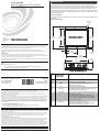
Physical Description
This section provides information on the connections, controls and indicators available on the
CSC-ACEX.
Dimensional Drawing
2.49 in
(64 mm)
1.84 in
(47 mm)
2.22 in
(57 mm)
0.19 in
(5 mm)
1.20 in
(31 mm)
2.20 in
(56 mm)
0.14 in
(4 mm)
Ø 0.15 in
(4 mm)
2.58 in
(66 mm)
0.68 in
(18 mm)
Crestron Electronics, Inc. Installation Guide - DOC. 7348D
15 Volvo Drive Rockleigh, NJ 07647 (2033154)
Tel: 888.CRESTRON 04.13
Fax: 201.767.7576 Specifications subject to
www.crestron.com change without notice.
Further Inquiries
To locate specific information or resolve questions after reviewing this guide, contact Crestron's True Blue Support at
1-888-CRESTRON [1-888-273-7876] or refer to the listing of Crestron worldwide offices on the Crestron Web site
(www.crestron.com/offices) for assistance within a particular geographic region.
To post a question about Crestron products, log onto the Online Help section of the Crestron Web site
(www.crestron.com/onlinehelp). First-time users must establish a user account to fully benefit from all available
features.
Future Updates
As Crestron improves functions, adds new features and extends the capabilities of the CSC-ACEX, additional
information may be made available as manual updates. These updates are solely electronic and serve as intermediary
supplements prior to the release of a complete technical documentation revision.
Check the Crestron Web site periodically for manual update availability and its relevance. Updates are identified as an
“Addendum” in the Download column.
WARNING: To avoid fire, shock, or death; turn off power at circuit breaker or fuse and test that power is off before
wiring!
NOTES: Observe the following points.
• To be installed and/or used in accordance with appropriate electrical codes and regulations.
• This product should be installed by a qualified electrician.
#
CONNECTORS,
CONTROLS &
INDICATORS
DESCRIPTION
1 ILT MOTOR RJ-11 connection to shade motor
2 UP Push button used to raise shade
3 SET Push button used to enter setup mode and enter
infiNET EX Acquire mode
4 DN Push button used to lower shade
5 SET LED Red LED indicates the infiNET EX acquire status, the
device setup status and error codes.
NET LED Amber LED used to indicate communication status of
the infiNET EX network;
LED is solid when the device is connected to the
network, flashes when connected to a gateway but
not to a control system and off when no connection to
control system or gateway
7 PWR LED Green LED indicates power and status;
LED blinks while the shade is moving. LED is solid
when shade is stopped and powered on

The specific patents that cover Crestron products are listed at patents.crestron.com.
Crestron, the Crestron logo and infiNET EX are either trademarks or registered trademarks of Crestron
Electronics, Inc. in the United States and/or other countries. Somfy is a trademark or registered
trademark of Somfy SAS in the United States and/or other countries. Other trademarks, registered
trademarks and trade names may be used in this document to refer to either the entities claiming the
marks and names or their products. Crestron disclaims any proprietary interest in the marks and names
of others. Crestron is not responsible for errors in typography or photography.
This document was written by the Technical Publications department at Crestron.
©2013 Crestron Electronics, Inc.
MOUNTING
The CSC-ACEX can be mounted to a single gang box or to any flat surface. Refer to the
appropriate procedure below for mounting instructions.
Mounting in Single Gang Box
The CSC-ACEX mounts to a single gang box by using the CSC-BRKT-1G (sold separately).
For installation details refer to the CSC-BRKT-1G Installation Guide (Doc. 7353) which is
available from the Crestron Web site (www.crestron.com/manuals).
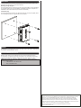
Surface Mounting
The CSC-ACEX can be mounted to any flat surface using four screws (not supplied). Refer
to the following illustration for a typical surface mount scenario.
WIRING
For information on wiring this device, refer to the latest version of the Crestron Roller Shades
and Interfaces Wiring Guide (Doc. 7516).
PROGRAMMING AND SETUP
Before the roller shade can be operated the device must be programmed and set up.
For information on programming and setup of this device, refer to the latest version of the
Crestron Roller Shades and Interfaces Programming and Setup Guide (Doc. 7361).
NOTE: Prior to setup and configuration, update the firmware in gateway or MC3 to the
following minimum revision:
• CEN-RFGW-EX: 2.001.0046 or later
• MC3: 1.003.0008 or later
-
 1
1
-
 2
2


dans d''autres langues
- English: Crestron CSC-ACEX Installation guide
Documents connexes
-
Crestron HZ-DIMLVEX Information produit
-
-
-
-
-
-
-
-
-