
www.elek-trends.be
Installatiehandleiding
Notice d’installation/Installation manual
OTUS
05/2018 - V 1 - NL-FR-ENG

2
NL
INTRODUCTIE
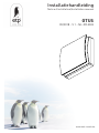
De Otus is een decentrale mechanische ventilatieunit, met afwisselende luchtstromen, met warmteterugwinning voor installatie in individuele
ruimtes. Deze unit is ontworpen om voldoende ventilatie in gesloten individuele ruimtes te waarborgen zonder energieverlies.
Het wordt aanbevolen om twee units in paralelle werking te installeren: wanneer een eenheid lucht toevoert, zal de andere de lucht afvoeren. De
verschillende units kunnen in dezelfde ruimte of in verschillende ruimtes (dwz woonkamer en slaapkamer) worden geïnstalleerd. De unit wordt
geïnstalleerd op een buitenmuur.
Lees deze handleiding zorgvuldig vooraleer het toestel in gebruik te nemen en bewaar deze op een veilige plaats als naslagwerk.
Dit product werd ontworpen volgens de geldende normen en in overeenstemming met de voorschriften inzake elektrische apparatuur en moet
worden geïnstalleerd door technisch gekwalificeerd personeel.
De fabrikant is niet aansprakelijk voor schade aan personen of eigendommen die ontstaan door het niet opvolgen van de instructies in deze
handleiding.
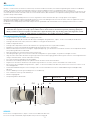
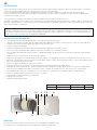
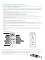
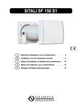
• Design voorpaneel (A), afneembaar voor reiniging zonder tools.
• Inwendige ventilatie unit (B) en muursteun basis (D) vervaardigd uit hoog kwalitatief-, impact- en UV-resistent ABS, kleur RAL 9010.
• Geïntegreerde multi-kleur led (C ) om visuele feedback te verkrijgen van de unitstatus.
• Slimme vochtigheidscontrole
• Geïntegreerde temperatuursensor voor de automatische regeleing van de inversietijd (comfort modus)
• Automatische antivries beveiliging om vorstopbouw op de warmtewisselaar te voorkomen..
• Muursteun basis (D) voorzien met een magneet “koppel/ontkoppeling” systeem dewelke toelaat dat de ventilatie unit verwijderd kan worden
van zijn basis gedurende het onderhoud.
• Back-up aanraaktoets (J) aan de zijkant van de ventilatie unit.
• Uniek design winglet-type schroef, voorziet verbeterde aerodynamische eigenschappen, stil geluid en verhoogde efficiëntie.
• Hoge efficiëntie omkeerbare EC motor met geïntegreerde thermische beveiliging, gemonteerd met gesloten voor het leven hoog kwalitatieve
rollagers. Ontwikkeld voor continue omkeerbare werking.
• Telescopische buis (F) aanpasbaar aan de wanddikte.
• Anti-mortel afschermkap, ontworpen als sjabloon voor de installatie van de muursteun basis.
• Regeneratieve keramische warmtewisselaar (G) met hoge thermische efficiëntie, voorzien van wasbare anti-stoffilters (H).
• Extern rooster (I) vervaardigd uit hoog kwalitatief-, impact- en UV-resistent ABS, kleur RAL 9010, voorzien van een anti-insectennet en een
waterafdrupgeleider.
• Infrarood afstandsbediening met touchtechnologie, LCD scherm en muurbasis voorzien als standaardbediening. Vervaardigd uit ABS,
RAL 9010.
• De unit is dubbel geïsoleerd: geen aardingsconnectie noodzakelijk.
• Geen condensatie afvoersysteem noodzakelijk
• IPX4 beveiligingsgraad.
• Netspanning 220V tot 240V~ 50Hz.
TECHNISCHE SPECIFICATIES
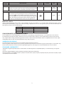
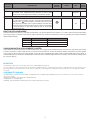
Model Debiet (m³/h) Vermogen (W) Gewicht (Kg)
Otus 20/30/40/50/60 2/2,5/3,5/4,5/6 5,9
Extern rooster in hoog kwalitatief-, impact- en UV-resistent ABS kleur RAL 9010.
Of een externe kap in aluminium, witgelakt (RAL 9010), acoustisch uitgelijnd.
VERSIES
De groep moet continu in werking zijn, en mag enkel uitgeschakeld worden voor onderhoud of herstelling.
Indien warmterecuperatie niet nodig is (bv in midden-seizoen wanneer buiten-en binnentemperatuur praktisch gelijk zijn aan
elkaar), of wanneer warmterecuperatie niet aanbevolen is (bijvoorbeeld bij optie “vrije koeling”), dan is het aangeraden om het
toestel op “enkel extractie of “enkel toevoer” in te stellen en niet uit te schakelen.
F
C
B
AE
D
GH
H
I
J

3
VOORZORGSMAATREGELEN VOOR DE INSTALLATIE, GEBRUIK EN ONDERHOUD
Model Debiet (m³/h) Vermogen (W) Gewicht (Kg)
Otus 20/30/40/50/60 2/2,5/3,5/4,5/6 5,9
• De unit mag niet gebruikt worden voor andere toepassingen dan deze gespecificeerd in deze handleiding.
• Controleer de unit na het uitpakken. Bij twijfel contacteer een gekwalificeerd technieker. Laat het verpakkingsmateriaal nooit binnen het
bereik van kinderen of mensen met een beperking.
• Raak de unit nooit aan met natte- of vochtige handen/voeten.
• De unit is niet bedoeld voor gebruik door personen (inclusief kinderen) met verminderde lichamelijke, zintuiglijke of geestelijke
vermogens of personen met een gebrek aan ervaring en kennis, tenzij ze onder toezicht staan of instructie krijgen over het gebruik van de
unit door een persoon die verantwoordelijk is voor hun veiligheid. Kinderen moeten onder toezicht staan om te vermijden dat ze met de
unit spelen.
• Gebruik de unit niet in aanwezigheid van brandbare gassen zoals: alcohol, insecticiden, benzine, enz.
• Van zodra er zich een probleem voordoet bij het gebruik van de unit, ontkoppelt u de unit en neemt onmiddellijk contact op met een
gekwalificeerd technicus. Gebruik enkel originele onderdelen voor herstelling.
• Het elektrisch net waarop de unit is aangesloten moet voldoen aan de geldende regelwetgeving.
• Vooraleer de unit op het elektriciteitsnet aan te sluiten controleer:
- of de gegevens op het identificatieplaatje (spanning en frequentie) overeenkomen met deze van het net.
- of de elektrische voeding/stopcontact voldoende is voor het max. vermogen van het toestel.
• Het toestel mag niet worden gebruikt in combinatie met boilers, fornuizen, enz.... De unit mag geen hete lucht/rook afvoeren van een
ander toestel zoals droogkast, verwarmingstoestellen, Deze lucht dient afgevoerd te worden door het voorziene kanaal.
• Werkingstemperatuur: -20°C tot +50 °C.
• De unit is enkel ontworpen om zuivere lucht te onttrekken d.w.z zonder vet, roet, chemische of bijtende stoffen, of ontvlambare- of
explosieve mengsels.
• Stel de unit niet bloot aan atmosferische invloeden (regen, zon, sneeuw, enz.).
• Dompel de unit of onderdelen niet onder in water of andere vloeistoffen.
• Schakel de hoofdschakelaar uit van zodra er zich een probleem voordoet of bij onderhoud van de unit.
• Voorzie voor de installatie reeds een meerpolige schakelaar in de elektrische bedrading volgens de geldende richtlijnen zodat bij
overspanning de installatie gegarandeerd spanningsvrij kan gemaakt worden (contactopening >of = 3mm).
• Als het netsnoer beschadigd is, moet het worden vervangen door de fabrikant, zijn installateur of personen met vergelijkbare kwalificaties
om gevaar te voorkomen.
• Blokkeer het uitlaatrooster of de ventilator niet om een optimale luchtdoorgang te garanderen.
• Zorg voor voldoende ventilatie toevoer/afvoer in/uit de kamer in overeenstemming met de bestaande regelgeving om te zorgen voor een
goede werking van de unit.
• Indien de unit geïnstalleerd is in een ruimte waar ook een toestel op brandstof aanwezig is, dient er voldoende verluchting te worden
voorzien om de goede werking van de unit te kunnen garanderen.
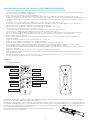
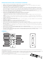
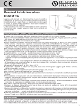
De unit wordt standaard geleverd met een infrarood afstandsbediening (K), alsook met zijn muursteun (L) dewelke op de muur bevestigd kan
worden. Een magneet bevestigd de bediening aan de steunbasis.
De bediening is uitgerust met een LCD scherm om het commando naar de unit te visualiseren, telkens wanneer een toets bediend wordt, wordt
het zichtbaar commando op het LCD scherm verzonden naar de unit. De IR ontvanger (zie afbeelding E pag.2) situeert zich op de linkerzijde van
de ventilatie unit. Het wordt aanbevolen om de bediening the richten naar de ontvanger wanneer een commando verzonden dient te worden.
Één afstandbediening kan meerdere units bedienen.
Het is noodzakelijk om twee type AAA batterijen in te brengen om de afstandsbediening
te laten functioneren (niet meegeleverd).
FILTER RESET TOETS
MODUS TOETS
MODUS ICOON
FILTER RESET ICOON
LUCHTSTROOMRICHTING ICOON
SNELHEID ICOON
BOOST ICOON
SNELHEID TOETSEN
LUCHTSTROOMRICHTING TOETS
BOOST TOETS
K L
AFSTANDSBEDIENING
external grille - installation
Ø5x40mm
5mm
cambio batterie telecomando
SNELHEID ICOON
WERKING
OFF TOETS
MODE
EFFICIENCY
COMFORT
OFF
FILTER
RESET

4
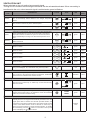
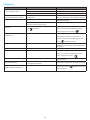
VENTILATIE UNIT
Bij het inschakelen geeft de unit een lang geluidssignaal.
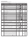
Via de IR afstandbediening kunnen onderstaande functionaliteiten geactiveerd/gedeactiveerd worden. Wanneer
een signaal verzonden wordt naar de unit geeft de unit een kort geluidssignaal en licht een groene LED op.
FUNCTIONA-
LITEIT
OMSCHRIJVING
BEDIENINGS-
TOETS
ICOON LED
GELUIDS-
SIGNAAL
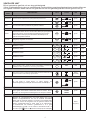
Luchtstroomrichting
Alternerend
De unit werkt afwisselend in toevoer/afvoer aan de gekozen snelheid: de inversietijd
wordt automatisch bepaald door de geïntegreerde temperatuursensor.
groen kort
Extractie De unit werkt enkel in extractie aan de gekozen snelheid. groen kort
Pulsie De unit werkt enkel in pulsie aan de gekozen snelheid. groen kort
Mode (enkel actief in alternerende luchtstroomrichting)
Comfort
Optimalisatie van het geluids- en thermisch comfort. De inversietijd
varieert automatisch van 40÷120 seconden dankzij de geïntegreerde
temperatuursensor. De eerste tijdcyclus bedraagt 120 seconden,
daarna varieert deze tijdcyclus automatisch afhankelijk van de
gemeten temperatuurswaarde.
groen kort
Efcientie
Optimalisering van de thermische efciëntie. De inversietijd is vast
geregeld op ongeveer 70 seconden.
groen kort
Continue werkingssnelheid
Snelheid 1: 20m³/h groen kort
Snelheid 2: 30m³/h groen kort
Snelheid 3: 40m³/h groen kort
Snelheid 4: 50m³/h groen kort
Snelheid 5: 60m³/h groen kort
Off positie
Druk 3 seconden op de toets om de unit uit te schakelen, u hoort een lang
geluidssignaal. Druk op een toets om de unit terug in te schakelen.
rood lang
BOOST snelheid
De unit werkt op snelheid 5 (maximum) in afvoer gedurende 15 minuten; daarna
keert het terug naar de voorgaande mode/snelheid. De BOOST snelheid kan niet
geactiveerd worden als de bediening uitgeschakeld is.
blauw
(constant)
kort
Vrije koeling
De unit werkt in “enkel afvoer” of “enkel toevoer” om
warmteterugwinning te vermijden wanneer dit niet noodzakelijk is.
groen kort
Filter reset
Elke 3 maanden licht een gele waarschuwingsled op (constant) om
aan te geven dat de lters onderhouden dienen te worden. Druk 5
seconden op de toegewezen bedieningstoets om de tijd te resetten.
groen kort
Slimme vochtigheidscontrole
Wanneer de vochtigheidssensor een snelle stijging meet op de
relatieve vochtigheidswaarde, dan zal de snelheid automatisch
stijgen naar de volgende snelheid. 10 minuten na de laatste snelle
RV variatie, zal de unit terugkeren naar de gekozen snelheid. De
slimme vochtigheidscontrole is enkel actief in de alternerende-
of extractiemode: als snelheid 5 geselecteerd is, is er geen
snelheidsstijging mogelijk. Om de functie te deactiveren drukt u 5
seconden op de toets: het symbool verschijnt op de LCD diplay.
blauw
(knipperend)
COMFORT
EFFICIENCY
OFF
FILTER
RESET
oppure
―
+
―
+
―
+
―
+
―
+
―
―
MODE
MODE

5
FUNCTIONA-
LITEIT
OMSCHRIJVING
BEDIENINGS-
TOETS
ICOON LED
GELUIDS-
SIGNAAL
Antivries
Deze functie voorkomt de opbouw van vorst op de warmtewisselaar
omwille van extreem koude lucht. Als de functie geactiveerd is zal de
unit enkel in afvoer werken op snelheid 1 gedurende 30 minuten.
rood
(constant)
Geluidssignaal
Telkens als er een signaal verzonden wordt van de bediening naar
de unit hoort u een kort geluidssignaal. Dit kan gedeactiveerd wor-
den door de toets in te drukkken gedurende 7 seconden, een
groene led knippert om aan te tonen dat de geluidsfunctie uitgescha-
keld is. Om deze terug te activeren dient er opnieuw gedurende 7
seconden op de toets gedrukt te worden tot u een signaal hoort.
groen kort
BACK-UP TOETS
Indien de afstandsbediening verloren raakt, of als de batterijen leeg zijn, kan snelheid 1, 3 of de OFF positie geselecteerd worden vanaf de
behuizingstoets (zie afbeelding J pag.2). De luchtstroomrichting is altijd alternerend en de werkingsmodus (zowel in comfort als efciëntie) is de
laatst gekozen functie met de afstandsbediening.
SYNCHRONISATIE VAN MEERDERE UNITS
Het is mogelijk om tot 10 units tegelijkertijd te synchroniseren, via bedrading (2 polig twisted-pair type , max. lengte 30m) om de modus en
inversietijd gesynchroniseerd te hebben. Wanneer de unit voor de eerste maal in werking is, zal de rotatierichting van elke unit (met de klok
mee of tegen de klok richting) automatisch gegenereerd worden. Andere functies zoals snelheid, slimme vochtigheidscontrole en boost, blijven
onafhankelijk werken op elke unit. Zie aansluitschema op g. 16 B (zie pag.16).
SNELHEID LED KLEUR GELUIDSIGNAAL
snelheid 1 enkele groene led kort, enkel
snelheid 3 dubbele groene led kort, dubbel
OFF rode led lang
2006/95/EC Laagspanningsrichtlijn (LVD) en 2004/108/EC de elektromagnetische compatibiliteit (EMC), in overeenstemming met volgende
normen.
Electrische veiligheid EN60335-1(2008); EN 60335-2-80(2005); EN 60335-2-80/A2(2009)
Electromagnetische compatibiliteit EN 55014-1(2006)+A1+A2; EN 55014-2(1997)+A1(2001)+A2(2008)+IS1(2007), EN 61000-3-2(2006)+A1(200
9)+A2(2009); EN 61000-3-3(2008).
Het onderhoud kan uitgevoerd worden door de gebruiker zoals aangeduid op pagina 15.
Service mag alleen worden uitgevoerd door technisch gekwaliceerd personeel in overeenstemming met de lokale regels en voorschriften. Zorg
ervoor dat de stroomtoevoer naar de unit wordt losgekoppeld (pagina 16). Het reinigen van de warmtewisselaar kan ook van buitenaf.
STANDAARD CONFORMITEIT
ONDERHOUD EN SERVICE

6
FR
INTRODUCTION
Otus est une unité de récupération de chaleur résidentielle décentralisée (point unique), également appelée unité «push & pull», conçue pour
assurer une ventilation adéquate dans des environnements fermés sans perte d’énergie.
Il est recommandé d’installer deux unités contemporanément afin que ces unites travaillent en couple (avec des flux synchronisés).
La paire d’unités peut être installée dans la même pièce ou dans différentes pièces (salon et chambre à coucher). L’unité est adaptée pour
l’installation sur un mur extérieur.
Lisez attentivement ce manuel avant d’utiliser le produit et garder le dans un endroit sûr pour référénce.
Ce produit a été fabriqué selon les normes et en conformité avec les réglementations relatives ou matériel électrique et doit être installé par une
personne technique qualifiée. Le fabricant décline toute responsabilité pour les dommages physiques ou matériels résultant de non-respect des
règles contenues dans cette brochure.
• Conception de la façade avant (A) amovible pour le nettoyage sans l’utilisation d’outils.
• Unité de ventilation intérieure (B) et base de support mural (D) en ABS de haute qualité, résistant aux chocs et aux UV, couleur RAL 9010.
• Led multicolore intégrée (C) pour obtenir un retour visuel de l’état de l’unité.
• Contrôle intelligent de l’humidité.
• Capteur de température intégré pour la gestion automatique du temps d’inversion (mode confort).
• Protection anti-gel automatique pour empêcher le givre de s’accumuler sur l’échangeur de chaleur.
• Base de support mural (D) munie d’un système de “couplage/découplage” qui permet de retirer l’unité de ventilation de sa base pendant
l’entretien.
• Bouton tactile de secours (J) sur le côté de l’unité de ventilation.
• Impeller de type winglet de conception unique, offrant des propriétés aérodynamiques améliorées, un faible bruit et une efficacité accrue.
• Moteur EC réversible haute efficacité avec protection thermique intégrée, monté sur des roulements à billes scellés de haute qualité. Conçu
pour le fonctionnement continu réversible.
• Tuyau téléscopique (F) adaptable à l’épaisseur de la paroi.
• Capuchon antimortarien conçu pour servir de gabarit lors de l’installation de la base de support mural.
• Échangeur de chaleur régénératif avec noyau céramique (G) à haut rendement thermique, équipé de filtres anti-poussière lavables (H).
• Grille externe (I) en ABS de haute qualité, résistant aux chocs et aux UV, couleur RAL 9010, avec filet anti-insectes et pare-gouttes.
• Télécommande infra-rouge avec technologie tactile, écran LCD et socle mural fournis en standard. Fabriqué en ABS, RAL 9010.
• L’unité est à double isolation: aucune mise à la terre n’est requise.
• Pas besoin de système de drainage de condensation.
• Degré de protection IPX4.
• Alimentation 220V à 240V ~ 50Hz.
SPÉCIFICATIONS TECHNIQUES
Type Debit (m³/h) Puissance (W) Poids (Kg)
Otus 20/30/40/50/60 2/2,5/3,5/4,5/6 5,9
Grille extérieure de haute qualité, résistant aux chocs et aux UV, ABS de couleur RAL 9010
ou le capot externe en aluminium, peint en blanc (RAL 9010), doublé acoustiquement.
VERSIONS
L’unité doit fonctionner en continu et ne doit être arrêtée que pour la maintenance ou l’entretien.
Lorsque l’échange de chaleur n’est pas utile (par exemple en mi-saison lorsque les températures intérieure et extérieure sont similaires),
ou lorsque l’échange de chaleur n’est pas recommandé (par exemple avec l’option «summer free cooling»), il est recommandé d’utiliser le
mode «extract-only» ou «intake only» et DE NE PAS L’ETEINDRE.
F
C
B
AE
D
GH
H
I
J

7
PRÉCAUTIONS D’INSTALLATION, D’UTILISATION ET D’ENTRETIEN
Type Debit (m³/h) Puissance (W) Poids (Kg)
Otus 20/30/40/50/60 2/2,5/3,5/4,5/6 5,9
• L’appareil ne doit pas être utilisé pour d’autres applications que celles spécifiées dans ce manuel.
• Après avoir retiré le produit de son emballage, vérifiez son état. En cas de doute, contactez un technicien qualifié. Ne laissez pas les
emballages à la portée d’enfants en bas âge ou de personnes handicapées.
• Ne touchez pas l’appareil avec des mains / pieds mouillés ou humides.
• Cet appareil peut être utilisé par des enfants âgés de 8 ans ou plus, par des personnes ayant des capacités physiques, sensorielles ou
mentales réduites ou bien un manque d’expérience et de connaissance si ils reçoivent une supervision ou des instructions concernant
l’utilisation de l’appareil en toute sécurité et si ils comprennent le danger impliqué par l’utilisation de cet appareil. Les enfants ne doivent
pas jouer avec l’appareil. Le nettoyage et la maintenance par l’utilisateur ne doivent pas être effectués par des enfants sans surveillance.
• N’utilisez pas le produit en présence de vapeurs inflammables, telles que de l’alcool, des insecticides, de l’essence, etc.
• En cas de détection d’anomalies, déconnectez l’appareil de la prise de courant et contactez immédiatement un technicien qualifié. Utilisez
les pièces de rechange d’origine uniquement pour les réparations.
• Le système électrique auquel l’appareil est connecté doit être conforme à la réglementation.
• Avant de connecter le produit à l’alimentation ou à la prise de courant, assurez-vous que:
- la plaque signalétique (tension et fréquence) correspond à celle du réseau électrique
- l’alimentation électrique / prise de courant est suffisante pour une puissance maximale de l’appareil. Sinon, contactez un technicien
qualifié.
• L’appareil ne doit pas être utilisé comme activateur pour les chauffe-eau, cuisinières, etc. et ne doit pas non plus se décharger dans les
conduits d’évacuation d’air chaud / de fumée provenant de n’importe quel type d’unité de combustion. Il doit expulser l’air à l’extérieur via
son propre conduit spécial.
• Température de fonctionnement: de -20°C à +50°C.
• L’appareil est conçu pour extraire uniquement de l’air propre, c’est-à-dire sans graisse, suie, agents chimiques ou corrosifs ou mélanges
inflammables ou explosifs.
• Ne laissez pas l’appareil exposé à des agents atmosphériques (pluie, soleil, neige, etc.).
• Ne plongez pas l’appareil ou ses composants dans l’eau ou d’autres liquides.
• Éteignez l’interrupteur principal lorsqu’un dysfonctionnement est détecté ou lors du nettoyage.
• Pour l’installation, un interrupteur omnipolaire doit être incorporé dans le câblage fixe, conformément aux réglementations de câblage,
pour assurer une déconnexion complète dans des conditions de surtension de catégorie III (distance d’ouverture des contacts égale ou
supérieure à 3 mm).
• Si le cordon d’alimentation est endommagé, il doit être remplacé par le fabricant, son agent de service ou des personnes de qualification
similaire afin d’éviter tout danger.
• N’obstruez pas le ventilateur ou la grille d’échappement pour assurer un passage d’air optimal.
• Assurer un retour / une évacuation d’air adéquat dans / depuis la pièce conformément aux réglementations en vigueur afin de garantir le
bon fonctionnement de l’appareil.
• Si l’environnement dans lequel le produit est installé abrite également un dispositif d’alimentation en combustible (chauffe-eau, réchaud
à méthane, etc., qui n’est pas de type «chambre étanche»), il est indispensable de garantir une bonne entrée d’air et le bon
fonctionnement de l’équipement.
L’unité est fournie avec une télécommande infrarouge (K), ainsi que sa base de support (L) qui peut être fixée au mur. Un aimant maintient la
télécommande attachée à la base.
la télécommande est équipée d’un écran LCD pour visualiser le réglage à transférer à l’unité; Chaque fois que vous appuyez sur un bouton tactile,
le réglage affiché sur l’écran LCD est transféré sur l’appareil. Le récepteur IR (image E page 6) est placé sur le côté gauche de l’unité de
ventilation: il est recommandé de pointer le contrôleur vers le récepteur quand un réglage doit être transféré.
Une télécommande peut contrôler plusieurs unités.
Pour activer la télécommande, il est nécessaire d’insérer deux piles de type AAA (non fournies).
BOUTON DU CHANGEMENT
DE FILTRE
BOUTON MODE
ICÔNE DU MODE
ICÔNE DE CHANGEMENT
DE FILTRE
ICÔNE DE DIRECTION
DU FLUX DE L’AIR
ICÔNE DE LA VITESSE
ICÔNE DU BOOST
BOUTONS DE LA VITESSE
BOUTON DE LA DIRECTION
DU FLUX DE L’AIR
BOUTON DU BOOST
K L
TÉLÉCOMMANDE
external grille - installation
Ø5x40mm
5mm
cambio batterie telecomando
ICÔNE DE LA VITESSE
OPÉRATION
BOUTON OFF
MODE
EFFICIENCY
COMFORT
OFF
FILTER
RESET

8
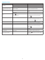
UNITÉ DE VENTILATION
Lorsqu’il est allumé, l’appareil émet un long signal sonore.
Grâce au contrôleur IR, les fonctionnalités suivantes peuvent être activées / désactivées. Lorsqu’un réglage est transféré à l’appareil, un court
signal acoustique est émis et un voyant vert clignote.
FONCTION-
NALITÉ
DESCRIPTION
TELECOMM.
BOUTON
ICONE LED
SIGNAL
ACOUSTI-
QUE
Direction du ux d’air
Alterné
L’unité fonctionne en extraction/absorption à la vitesse sélectionnée:
le temps d’inversion est automatiquement déni grâce au capteur de
température intégré.
vert court
Extraction L’unité fonctionne en extraction uniquement à la vitesse sélectionnée. vert court
Absorption
L’unité fonctionne en absorption uniquement à la vitesse
sélectionnée.
vert court
Mode (actif uniquement si la direction du ux d’air est activée)
Comfort
Optimisation du confort acoustique et thermique. Le temps d’inversion
varie automatiquement de 40÷120 secondes, grâce à l’integrel
capteur de température. Le premier cycle de temps est de 120
secondes, puis il varie automatiquement en fonction des conditions
de température détectées.
vert court
Efcacité
Optimisation de l’efcacité thermique. Le temps d’inversion est xé à
environ 70 secondes.
vert court
Vitesse de fonctionnement continu
Vitesse 1: 20m³/h vert court
Vitesse 2: 30m³/h vert court
Vitesse 3: 40m³/h vert court
Vitesse 4: 50m³/h vert court
Vitesse 5: 60m³/h vert court
Position arrêt
En appuyant sur le bouton pendant 3 secondes, les unités
s’éteignent, émettant un signal acoustique long. Pour réactiver
l’appareil, appuyez sur n’importe quel bouton.
rouge long
Vitesse BOOST
L’unité fonctionne à la vitesse 5 (maximum) pendant 15 minutes,
en extraction; puis il revient au mode / vitesse précédemment
sélectionné. La vitesse BOOST ne peut pas être activée si le
contrôleur est désactivé.
bleu xe court
Free cooling
L’unité fonctionne en “extraction” ou “Absorption” pour éviter la
récupération de chaleur quand pas nécessaire.
vert court
Reset de ltre
Tous les 3 mois, une led d’avertissement jaune s’allume (lumière xe)
pour indiquer que les ltres doivent être maintenus. Appuyez sur le
bouton dédié pour 5 secondes pour réinitialiser le chronométrage.
vert court
Contrôle intelligent de l’humidité
Lorsque le capteur d’humidité détecte une variation rapide du Relative
Niveau d’humidité, la vitesse de course augmente automatiquement
à la prochaine vitesse plus élevée. Après 10 minutes de la dernière
variation rapide de RH, l’unité retourne à la vitesse sélectionnée. Le
contrôle intelligent de l’humidité est actif si la direction du ux d’air
est réglée sur alterné ou extrait uniquement: si la vitesse 5 a été
sélectionné, aucune augmentation de la vitesse ne se produit. Pour
désactiver cette fonctionnalité, appuyez sur le bouton pendant 5
secondes: sur le dessus de l’écran LCD le symbole est montré.
bleu
clignotant
COMFORT
EFFICIENCY
OFF
FILTER
RESET
ou
―
+
―
+
―
+
―
+
―
+
―
―
MODE
MODE

9
2014/35 / UE Directive Basse Tension (LVD) et Compatibilité Electromagnétique (CEM) 2014/30 / UE, en conformité avec les normes suivantes:
Sécurité électrique
EN60335-1(2012)+A11+A13; EN 60335-2-80(2003)+A1+A2
Compatibilité électromagnétique
EN 55014-1(2017); EN 55014-2(2015); EN 61000-3-2(2014); EN 61000-3-3(2013).
La maintenance peut être effectuée par l’utilisateur comme indiqué à la page 13.
Le service doit être réalisé seulement par une personne technique qualifiée, conformément aux règles et réglementations locales. Assurez-vous
que l’alimentation électrique de l’unité est déconnectée (page 16). Le nettoyage de l’échangeur de chaleur peut être effectué également depuis
l’éxtérieur.
ENTRETIEN
CONFORMITÉ STANDARD
FONCTION-
NALITÉ
DESCRIPTION
TELECOM-
MANDE
BOUTON
ICONE LED
SIGNAL
ACOU-
STIQUE
Antigel
Cette fonctionnalité empêche le givre de s’accumuler sur l’échangeur
de chaleur à l’air extrêmement froid. Quand il est activé, l’unité
fonctionne en extrait uniquement à vitesse 1, pendant 30 minutes.
rouge xe
Acoustic signal
Chaque fois qu’un paramètre est transféré du contrôleur à l’unité,
un court signal acoustique est émis. Cela peut être désactivé en
appuyant sur lessss bouton pendant 7 secondes, après que le voyant
vert clignote pour indiquer que le signal acoustique soit éteint. Pour
réactiver le signal acoustique répéter la même fonctionnement pendant
7 secondes jusqu’à ce que la led devienne verte et qu’un signal
acoustique soit émis.
vert court
BOUTON DE SAUVEGARDE
Si la télécommande est perdue ou si les piles sont épuisées, vous pouvez sélectionner les vitesses 1, 3 et OFF à partir du bouton tactile intégré
(voir image J pag.6). La direction du ux d’air est toujours alternée et le mode de fonctionnement (confort ou efcacité) est le dernier sélectionné
depuis la télécommande.
SYNCHRONISATION D’UN NOMBRE D’UNITÉS
Il est possible de synchroniser jusqu’à 10 unités simultanément, via un l (type à paire torsadée à 2 pôles, longueur max. 30m) an de synchroniser
le mode et l’inversion. Lorsque l’unité est mise en marche pour la première fois, le sens de rotation de chaque unité (dans le sens des aiguilles
d’une montre ou dans le sens inverse des aiguilles d’une montre) est automatiquement établi. D’autres fonctionnalités telles que la vitesse, le
contrôle intelligent de l’humidité et la suralimentation continuent d’être contrôlées indépendamment sur chaque unité. Schéma de câblage selon
Fig. 16 B (voir pag.16).
VITESSE LED COULEUR SIGNAL ACOUSTIQUE
Vitesse 1 unique led vert court, unique
Vitesse 3 double led verte court, double
ETEINT led rouge long

10
ENG
INTRODUCTION
Otus is a single alternate flow decentralized (single point) residential heat recovery unit, also called «push&pull» unit, designed to ensure
adequate ventilation in enclosed environments without energy losses.
It is recommended that two units are installed in a pair: when one unit is pulling, the other is pushing.
The pair of units can be installed in the same room or in different rooms (i.e. living-room and bedroom). The unit is suitable for installation on an
outside wall.
Read this manual carefully before using the product and keep it in a safe place for reference.
This product was constructed up to standard and in compliance with regulations relating to electrical equipment and must be installed by
technically qualified personnel. The manufacturer assumes no responsibility for damage to persons or property resulting from failure to observe
the regulations contained in this booklet.
• Design front cover (A) removable for cleaning without the use of tools.
• Inner ventilation unit (B) and wall support base (D) made of high quality, impact and UV-resistant ABS, colour RAL 9010.
• Integrated multi-colour led (C ) to obtain a visual feedback of the unit status.
• Smart humidity control
• Integral temperature sensor for the automatic management of the inversion time (comfort mode)
• Automatic anti-frost protection to prevent frost building up on the heat exchanger.
• Wall support base (D) provided with a magnet “coupling/uncoupling” system which allows the ventilation unit to be removed from its base
during maintenance.
• Back-up touch button (J) at the side of the ventilation unit
• Unique design winglet-type impeller, providing enhanced aerodynamic properties, low noise and increased efficiency.
• High efficient reversible EC motor with integral thermal protection, mounted on sealed for life high quality ball bearings.
Designed for continuous reversible running.
• Telescopic pipe (F) adaptable to the wall thickness.
• Antimortar cap designed to be used also as template during the installation of the wall support base
• Regenerative heat exchanger with ceramic core (G) with high thermal efficiency, equipped with washable anti-dust filters (H).
• External grille (I) made of high quality, impact and UV-resistant ABS, colour RAL 9010, with anti-insect net and water drip guard.
• Infra-red remote controller with touch technology, LCD display and wall base supplied as standard. Made from ABS, RAL 9010.
• The unit is double insulated: no earth connection is required.
• No need of condensation drainage system
• IPX4 degree of protection.
• Power supply 220V to 240V~ 50Hz.
TECHNICAL SPECIFICATIONS
Model Airflow (m³/h) Power (W) Weight (Kg)
Otus 20/30/40/50/60 2/2,5/3,5/4,5/6 5,9
External grille in high quality, impact and UV-resistant ABS colour RAL 9010.
or external hood in aluminium, painted in white (RAL 9010), acoustically lined.
VERSIONS
The unit should operate continuously, and only stopped for maintenance or service.
When heat exchange is not useful (for example in mid-seasons when indoor and outdoor temperatures are similar), or when heat
exchange is not recommended (for example with the option “summer free cooling”), it is recommended to set the unit in “extract-only” or
“intake-only” mode and NOT to switch it off.
F
C
B
AE
D
GH
H
I
J

11
PRECAUTIONS FOR INSTALLATION, USE AND MAINTENANCE
Model Airflow (m³/h) Power (W) Weight (Kg)
Otus 20/30/40/50/60 2/2,5/3,5/4,5/6 5,9
• The device should not be used for applications other than those specified in this manual.
• After removing the product from its packaging, verify its condition. In case of doubt, contact a qualified technician. Do not leave packaging
within the reach of small children or people with disabilities.
• Do not touch the appliance with wet or damp hands/feet.
• This appliance can be used by children aged from 8 years and above and persons with reduced physical, sensory or mental capabilities or
lack of experience and knowledge if they have been given supervision or instruction concerning use of the appliance in a safe way and
understand the hazards involved. Children shall not play with the appliance. Cleaning and user maintenance shall not be made by children
without supervision.
• Do not use the product in the presence of inflammable vapours, such as alcohol, insecticides, gasoline, etc.
• If any abnormalities in operation are detected, disconnect the device from the mains supply and contact a qualified technician
immediately. Use original spare parts only for repairs.
• The electrical system to which the device is connected must comply with regulations.
• Before connecting the product to the power supply or the power outlet, ensure that:
- the data plate (voltage and frequency) correspond to those of the electrical mains
- the electrical power supply/socket is adequate for maximum device power. If not, contact a qualified technician.
• The device should not be used as an activator for water heaters, stoves, etc., nor should it discharge into hot air/fume vent ducts deriving
from any type of combustion unit. It must expel air outside via its own special duct.
• Operating temperature: -20°C up to +50°C.
• The device is designed to extract clean air only, i.e. without grease, soot, chemical or corrosive agents, or flammable or explosive
mixtures.
• Do not leave the device exposed to atmospheric agents (rain, sun, snow, etc.).
• Do not immerse the device or its parts in water or other liquids.
• Turn off the main switch whenever a malfunction is detected or when cleaning.
• For installation an omnipolar switch should be incorporated in the fixed wiring, in accordance with the wiring regulations, to provide a full
disconnection under overvoltage category III conditions (contact opening distance equal to or greater than 3mm).
• If the supply cord is damaged, it must be replaced by the manufacturer, its service agent or similarly qualified persons in order to avoid a
hazard.
• Do not obstruct the fan or exhaust grille to ensure optimum air passage.
• Ensure adequate air return/discharge into/from the room in compliance with existing regulations in order to ensure proper device
operation.
• If the environment in which the product is installed also houses a fuel-operating device (water heater, methane stove etc., that is not a
“sealed chamber” type), it is essential to ensure adequate air intake, to ensure good combustion and proper equipment operation.
The unit is supplied with an infrared remote controller (K) as standard, as well as its support base (L) which can be wall mounted. A magnet
keeps the controller attached to the base.
The controller is equipped with an LCD display to visualise the setting to be transferred to the unit; anytime a touch button is pressed, the setting
shown on the LCD display is transferred to the unit. The IR receiver (see image E pag.7) is placed on the left side of the ventilation unit: it is
recommended to point the controller towards the receiver when any setting needs to be transfered.
One remote controller can control more units.
To activate the remote controller it is necessary to insert two AAA type batteries (not supplied).
FILTER RESET BUTTON
MODE BUTTON
MODE ICON
FILTER RESET ICON
AIR FLOW DIRECTION ICON
SPEED ICON
BOOST ICON
SPEED BUTTONS
AIRFLOW DIRECTION BUTTON
BOOST BUTTON
K L
REMOTE CONTROLLER
external grille - installation
Ø5x40mm
5mm
cambio batterie telecomando
SPEED ICON
OPERATIONS
OFF BUTTON
MODE
EFFICIENCY
COMFORT
OFF
FILTER
RESET

12
VENTILATION UNIT
When switched on the unit emits a long acoustic signal.
Through the IR controller the following functionalities can be activated/deactivated. When one setting is
transferred to the unit, a short acoustic signal is emitted and a green led ashes.
FUNCTIONA-
LITY
DESCRIPTION
CONTROLLER
BUTTON
ICON LED
ACOUSTIC
SIGNAL
Airow direction
Alternate
The unit runs in extract/intake at the selected speed: the inversion
time is automatically dened thanks to the integrel temperature
sensor.
green short
Extract The unit runs in extract only at the selected speed. green short
Intake The unit runs in intake only at the selected speed. green short
Mode (active only if the airow direction is set on alternate)
Comfort
Optimisation of the acoustic and thermal comfort. The inversion time
varies automatically from 40÷120 seconds, thanks to the integrel
temperature sensor. The rst time cycle is of 120 seconds, then it
varies automatically according to the detected temperature condi-
tions.
green short
Efciency
Optimisation of the thermal efciency. The inversion time is xed at
about 70 seconds.
green short
Continuous running speed
Speed 1: 20m³/h green short
Speed 2: 30m³/h green short
Speed 3: 40m³/h green short
Speed 4: 50m³/h green short
Speed 5: 60m³/h green short
Off position
Pressing the button for 3 seconds, the units switches off, emitting
a long acoustic signal. To re-activate the unit, press any button.
red long
BOOST speed
The unit runs at speed 5 (maximum) for 15 minutes, in extract only;
then it returns to the previously selected mode/speed. The BOOST
speed cannot be activated if the controller is OFF.
xed blue short
Free cooling
The unit runs in “extract only” or “intake only” to avoid heat recovery
when not needed.
green short
Filter reset
Every 3 months a yellow warning led switches on (xed light) to
indicate that the lters have to be maintained. Press the dedicated
button for 5 seconds to reset the timing.
green short
Smart humidity control
When the humidity sensor detects a quick variation of the Relative
Humidity level, the running speed automatically increases to the next
higher speed. After 10 minutes from the last quick RH variation, the
unit returns running at the selected speed. The smart humidity control
is active if the airow direction is set on alternate or extract only: if
speed 5 has been selected, no speed increase happens. To disable
this functionality, press the button for 5 seconds: on the top side
of the LCD display the symbol is shown.
ashing
blue
COMFORT
EFFICIENCY
OFF
FILTER
RESET
oppure
―
+
―
+
―
+
―
+
―
+
―
―
MODE
MODE

13
STANDARD CONFORMITY
2006/95/EC Low Voltage Directive (LVD) and 2004/108/EC Electromagnetic Compatibility (EMC), in conformity with the following standards:
Electrical Safety EN60335-1(2008); EN 60335-2-80(2005); EN 60335-2-80/A2(2009)
Electromagnetic Compatibility EN 55014-1(2006)+A1+A2; EN 55014-2(1997)+A1(2001)+A2(2008)+IS1(2007), EN 61000-3-2(2006)+A1(2009)
+A2(2009); EN 61000-3-3(2008).
Maintenance can be carried out by the user as indicated at page 15
Service must be performed only by technically qualified personnel in accordance with local rules and regulations. Make sure that the mains
supply to the unit is disconnected (page 16). Cleaning of the heat exchanger can be performed from outside as well.
MAINTENANCE AND SERVICE
FUNCTIONA-
LITY
DESCRIPTION
CONTROL-
LER BUTTON
ICON LED
ACOU-
STIC
SIGNAL
Antifrost
This functionality prevents frost building up on the heat exchanger
due to extremely cold air. When it is activated, the unit runs in
extract only at speed 1, for 30 minutes.
xed red
Acoustic signal
Any time a setting is transferred from the controller to the unit, a
short acoustic signal is emitted. This can be deactivated by pressing
the button for 7 seconds, after when a green led ashes to
indicate that the acoustic signal is off. To reactivate the acoustic si-
gnal repeat the same operation for 7 seconds until the led becomes
green and an acoustic signal is emitted.
green short
BACK UP BUTTON
In case the remote controller gets lost or the batteries are dead, speeds 1, 3 and OFF position can be selected from the on board touch button
(see image J pag.10). The airow direction is always alternate and the operation mode (either comfort or efciency) is the last selected from the
remote controller.
SYNCHRONISATION OF A NUMBER OF UNITS
It is possible to synchronized up to 10 units contemporaneously, through wire (2 pole twisted pair type , max 30m length) so to have mode and
inversion time synchronized. When the unit is switched on for the rst time, the rotation direction of each unit (clockwise or anti-clockwise) is
automatically established. Other functionalities like speed, smart humidity control and boost , continue to be controlled independently on each
single unit. Wiring diagram as per Fig. 16 B (see pag.16).
SPEED LED COLOUR ACOUSTIC SIGNAL
speed 1 single green led short, single
speed 3 double green led short, double
OFF red led long

14
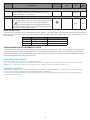
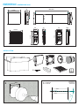
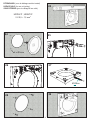
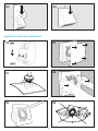
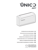
INSTALLATION
AFMETINGEN (mm)
DIMENSIONS (mm) - DIMENSIONS (mm)
218
76
G
ØH
q
A
B
C
G
ØH
q
A
B
C
G
ØH
q
A
B
C
G
ØH
q
A
B
C
300÷560
270÷510
164
q
164
q
108
O
mm
Ø158
218
Questo documento è protetto d alle leggi vigenti in materia di pr ivacy e copyright. Nè è vietata la copia, l a diffusione senza
autorizzazione di Aerauliqa srl
This document is protected by pri vacy and copyright laws. No part of this docum ent may be reproduced, adapted, trasm itted or
disclosed without the specific writte n consent of Aerauliqa srl. All right are reserved.
aera aqi lu
AERAULIQA SRL
Sede legale / Registered office: via Corsica 10, 25125 Brescia
Sede operativa / Warehouse-offices: via M.Calderara 39 / 41
25018 Montichiari (Bs)
Tel: +39 030 674681 Fax: +39 030 6872149
C.F. e P.IVA 03369930981 - REA BS-528635 www.aerauliqa.it
Descrizione/Description:
Materiale/Material: Data/Date: Firma/Signature:
Terraroli Stefano15/12/2017-
Telecomando Quantum Next
dimensioni
Rev. Descrizione/Description Data/Date Firma/Sign.
-- - TS
\Progetti\..\
ARCHIVIO CAD:
AQD.01178.00
003036
1:1
No. Dis/No. Drawing: Codice/Code: Scala/Scale:
-
Peso/Weight:
124
44
26,5
117,5
39
23
39
23
117,5
Questo documento è protetto d alle leggi vigenti in materia di pr ivacy e copyright. Nè è vietata la copia, l a diffusione senza
autorizzazione di Aerauliqa srl
This document is protected by pri vacy and copyright laws. No part of this docum ent may be reproduced, adapted, trasm itted or
disclosed without the specific writte n consent of Aerauliqa srl. All right are reserved.
aera aqi lu
AERAULIQA SRL
Sede legale / Registered office: via Corsica 10, 25125 Brescia
Sede operativa / Warehouse-offices: via M.Calderara 39 / 41
25018 Montichiari (Bs)
Tel: +39 030 674681 Fax: +39 030 6872149
C.F. e P.IVA 03369930981 - REA BS-528635 www.aerauliqa.it
Descrizione/Description:
Materiale/Material: Data/Date: Firma/Signature:
Terraroli Stefano15/12/2017-
Telecomando Quantum Next
dimensioni
Rev. Descrizione/Description Data/Date Firma/Sign.
-- - TS
\Progetti\..\
ARCHIVIO CAD:
AQD.01178.00
003036
1:1
No. Dis/No. Drawing: Codice/Code: Scala/Scale:
-
Peso/Weight:
124
44
26,5
117,5
39
23
44
26,5
124
contenuto imballo modello Quantum NEXT
1°
÷
2°
indoor
outdoor
colorare filtro e strisce mousse
EXTERIEUR
EXTÉRIEUR
EXTERIOR
INTERIER
INTÉRIEUR
INTERIOR
1
contenuto imballo modello Quantum NEXT
1°
÷
2°
indoor
outdoor
colorare filtro e strisce mousse
contenuto imballo modello Quantum NEXT
1°
÷
2°
indoor
outdoor
colorare filtro e strisce mousse
contenuto imballo modello Quantum NEXT
1°
÷
2°
indoor
outdoor
colorare filtro e strisce mousse
sostituire possibilmente solo il tubo nell'immagine "contenuto imballo"
fig.1
2
3
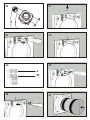
contenuto imballo modello Quantum NEXT (sostituisce immagine 1 )
10 x
sostituisce la nr°4
sostituisce la nr°6
sostituisce la nr°7
(e la 9 aggiungendo
le relative frecce)
contenuto imballo modello Quantum NEXT (sostituisce immagine 1 )
10 x
sostituisce la nr°4
sostituisce la nr°6
sostituisce la nr°7
(e la 9 aggiungendo
le relative frecce)
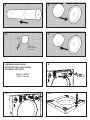
min. 158mm

15
6
Isolatieschuim
Mousse d’isolation
Isolation foam
5
4
7
VERZONKEN KABELINGANG
ENTRÉE DE CÂBLE ENCASTRÉE
RECESSED CABLE ENTRY
H03VV-F ; H05VV-F
2 X 0,5 ÷ 1,5 mm
2
8
aggiungere freccia
x aprire il coperchietto
aggiungere freccia
x togliere passacavo
apertura presfondabile
aggiungere freccia
x chiudere il coperchietto
colorare filtro e strisce mousse
aggiungere frecce
inserimento scambiatore
INIZIO INSTALLAZIONE
SOTTOTRACCIA
Ø 5 mm
Ø 5 mm
Ø 5 mm
Ø 5 mm
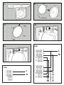
COLLEGAMENTI
ELETTRICI
aggiungere freccia
x aprire il coperchietto
aggiungere freccia
x togliere passacavo
apertura presfondabile
aggiungere freccia
x chiudere il coperchietto
colorare filtro e strisce mousse
aggiungere frecce
inserimento scambiatore
INIZIO INSTALLAZIONE
SOTTOTRACCIA
Ø 5 mm
Ø 5 mm
Ø 5 mm
Ø 5 mm
COLLEGAMENTI
ELETTRICI
9
aggiungere freccia
x aprire il coperchietto
aggiungere freccia
x togliere passacavo
apertura presfondabile
aggiungere freccia
x chiudere il coperchietto
colorare filtro e strisce mousse
aggiungere frecce
inserimento scambiatore
INIZIO INSTALLAZIONE
SOTTOTRACCIA
Ø 5 mm
Ø 5 mm
Ø 5 mm
Ø 5 mm
COLLEGAMENTI
ELETTRICI
aggiungere freccia
x aprire il coperchietto
aggiungere freccia
x togliere passacavo
apertura presfondabile
aggiungere freccia
x chiudere il coperchietto
colorare filtro e strisce mousse
aggiungere frecce
inserimento scambiatore
INIZIO INSTALLAZIONE
SOTTOTRACCIA
Ø 5 mm
Ø 5 mm
Ø 5 mm
Ø 5 mm
COLLEGAMENTI
ELETTRICI
10

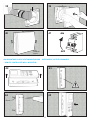
16
12
11
14
13
15
L
N
R
R
B
B
L
N
L
N
16B
L
N
16A
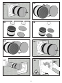
4 x Ø5mm

17
17
20
21
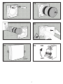
KLIK
CLAQUE
CLICK
aggiungere ai lati del prodotto
simboli di "avvenuto aggancio"
ON
OFF
aggiungere frecce
x install parte ventilante
115 mm
colorare filtro
22
18
19

18
23
24
INIZIO INSTALLAZIONE
SUPERFICIE
Ø 5 mm
Ø 5 mm
Ø 5 mm
Ø 5 mm
aggiungere freccia
x aprire il coperchietto
aggiungere freccia
x togliere passacavo
apertura presfondabile
Ø 10 mm
aggiungere freccia
x inserimento passacavo
aggiungere freccia
x svitare viti fermacavo
aggiungere freccia
x avvitare viti fermacavo
aggiungere freccia
x chiudere il coperchietto
COLLEGAMENTI
ELETTRICI
27
EXTERNE KABEL (voor de kablage van één toestel)
SURFACE CABLE (for one unit wiring)
CÂBLE EXTÉRIEUR (pour le câblage d’une unité)
H03VV-F ; H05VV-F
2 X 0,5 ÷ 1,5 mm
2
25
aggiungere freccia
x aprire il coperchietto
aggiungere freccia
x togliere passacavo
apertura presfondabile
aggiungere freccia
x chiudere il coperchietto
colorare filtro e strisce mousse
aggiungere frecce
inserimento scambiatore
INIZIO INSTALLAZIONE
SOTTOTRACCIA
Ø 5 mm
Ø 5 mm
Ø 5 mm
Ø 5 mm
COLLEGAMENTI
ELETTRICI
aggiungere freccia
x aprire il coperchietto
aggiungere freccia
x togliere passacavo
apertura presfondabile
aggiungere freccia
x chiudere il coperchietto
colorare filtro e strisce mousse
aggiungere frecce
inserimento scambiatore
INIZIO INSTALLAZIONE
SOTTOTRACCIA
Ø 5 mm
Ø 5 mm
Ø 5 mm
Ø 5 mm
COLLEGAMENTI
ELETTRICI
26
aggiungere freccia
x aprire il coperchietto
aggiungere freccia
x togliere passacavo
apertura presfondabile
aggiungere freccia
x chiudere il coperchietto
colorare filtro e strisce mousse
aggiungere frecce
inserimento scambiatore
INIZIO INSTALLAZIONE
SOTTOTRACCIA
Ø 5 mm
Ø 5 mm
Ø 5 mm
Ø 5 mm
COLLEGAMENTI
ELETTRICI
Ø10mm
29
28
4 x Ø5mm

19
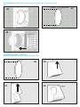
INIZIO INSTALLAZIONE
SUPERFICIE
Ø 5 mm
Ø 5 mm
Ø 5 mm
Ø 5 mm
aggiungere freccia
x aprire il coperchietto
aggiungere freccia
x togliere passacavo
apertura presfondabile
Ø 10 mm
aggiungere freccia
x inserimento passacavo
aggiungere freccia
x svitare viti fermacavo
aggiungere freccia
x avvitare viti fermacavo
aggiungere freccia
x chiudere il coperchietto
COLLEGAMENTI
ELETTRICI
L
N
30 31
32
34
35
36
37
33

20
aggiungere ai lati del prodotto
simboli di "avvenuto aggancio"
ON
OFF
aggiungere frecce
x install parte ventilante
115 mm
aggiungere frecce
x aggancio telecomando dalla base
Ø 5 mm
aggiungere frecce
x distacco telecomando dalla base
aggiungere scritte
ALTO - TOP
colorare filtro e strisce mousse
frecce inserimento scambiatore
40
41
42
43
44
45
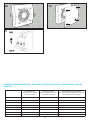
MUURMONTAGE VAN DE AFSTANDSBEDIENING - MONTAGE DE LA TÉLÉCOMMANDE
39
Ø5mm
38
- REMOTE CONTROLLER WALL MOUNTING
KLIK
CLAQUE
CLICK
La page est en cours de chargement...
La page est en cours de chargement...
La page est en cours de chargement...
La page est en cours de chargement...
La page est en cours de chargement...
La page est en cours de chargement...
La page est en cours de chargement...
La page est en cours de chargement...
La page est en cours de chargement...
La page est en cours de chargement...
La page est en cours de chargement...
La page est en cours de chargement...
-
 1
1
-
 2
2
-
 3
3
-
 4
4
-
 5
5
-
 6
6
-
 7
7
-
 8
8
-
 9
9
-
 10
10
-
 11
11
-
 12
12
-
 13
13
-
 14
14
-
 15
15
-
 16
16
-
 17
17
-
 18
18
-
 19
19
-
 20
20
-
 21
21
-
 22
22
-
 23
23
-
 24
24
-
 25
25
-
 26
26
-
 27
27
-
 28
28
-
 29
29
-
 30
30
-
 31
31
-
 32
32


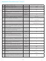
dans d''autres langues
- English: etp Otus Installation guide
- Nederlands: etp Otus Installatie gids
Autres documents
-
aerauliqa Quantum NEXT Manuel utilisateur
-
-
sauter BOLERO RADIATEURS Le manuel du propriétaire
-
 noken 100280524 Manuel utilisateur
-
 Olimpia Splendid Sitali SF150 S1 Manuel utilisateur
-
 Olimpia Splendid Sitali SF150 Manuel utilisateur
-
Alecto WS-5300 Manuel utilisateur
-
Listo CM7 L5 Le manuel du propriétaire
-
ELICA Shining Rust Manuel utilisateur
-
 Olimpia Splendid Unico Art Manuel utilisateur


