Garland 36ER32 Owner Instruction Manual
- Catégorie
- Fours
- Taper
- Owner Instruction Manual

Part # 1009067 Rev13 (12/04/09) Page 1
Users are cautioned that maintenance and repairs must be performed by a Garland authorized service agent
using genuine Garland replacement parts. Garland will have no obligation with respect to any product that has been
improperly installed, adjusted, operated or not maintained in accordance with national and local codes or installation
instructions provided with the product, or any product that has its serial number defaced, obliterated or removed,
or which has been modified or repaired using unauthorized parts or by unauthorized service agents.
For a list of authorized service agents, please refer to the Garland web site at http://www.garland-group.com.
The information contained herein, (including design and parts specifications), may be superseded and is subject
to change without notice.
GARLAND COMMERCIAL INDUSTRIES, LLC
185 East South Street
Freeland, Pennsylvania 18224
Phone: (570) 636-1000
Fax: (570) 636-3903
GARLAND COMMERCIAL RANGES, LTD.
1177 Kamato Road, Mississauga, Ontario L4W 1X4
CANADA
Phone: 905-624-0260
Fax: 905-624-5669
Enodis
U
Swallow e
Telephone
:
Fax: 081-8
4
Part # 1009067 Rev13 (12/04/09) © 2004 Garland Commercial Industries, LLC
FOR YOUR SAFETY:
DO NOT STORE OR USE GASOLINE
OR OTHER FLAMMABLE VAPORS OR
LIQUIDS IN THE VICINITY OF
THIS OR ANY OTHER
APPLIANCE
WARNING:
IMPROPER INSTALLATION, ADJUSTMENT,
ALTERATION, SERVICE OR MAINTENANCE
CAN CAUSE PROPERTY DAMAGE, INJURY,
OR DEATH. READ THE INSTALLATION,
OPERATING AND MAINTENANCE
INSTRUCTIONS THOROUGHLY
BEFORE INSTALLING OR
SERVICING THIS EQUIPMENT
INSTALLATION AND
OPERATION MANUAL
GARLAND 36 E SERIES
HEAVY DUTY ELECTRIC
RANGES AND BROILERS
PLEASE READ ALL SECTIONS OF THIS MANUAL
AND RETAIN FOR FUTURE REFERENCE.
THIS PRODUCT HAS BEEN CERTIFIED AS
COMMERCIAL COOKING EQUIPMENT AND
MUST BE INSTALLED BY PROFESSIONAL
PERSONNEL AS SPECIFIED.
INSTALLATION AND ELECTRICAL CONNECTION
MUST COMPLY WITH CURRENT CODES:
IN CANADA - THE CANADIAN ELECTRICAL
CODE PART 1 AND / OR LOCAL CODES.
IN USA – THE NATIONAL ELECTRICAL CODE
ANSI / NFPA – CURRENT EDITION.
ENSURE ELECTRICAL SUPPLY CONFORMS WITH
ELECTRICAL CHARACTERISTICS SHOWN ON
THE RATING PLATE.

Part # 1009067 Rev13(12/04/09)Page 2
IMPORTANT INFORMATION
WARNING:
This product contains chemicals known to the state of california to cause cancer and/or birth defects
or other reproductive harm. Installation and servicing of this product could expose you to airborne
particles of glass wool/ceramic fibers. Inhalation of airborne particles of glass wool/ceramic fibers
is known to the state of California to cause cancer.

Part # 1009067 Rev13 (12/04/09) Page 3
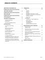
TABLE OF CONTENTS
IMPORTANT INFORMATION.............2
DIMENSIONS AND SPECIFICATIONS,
36E SERIES RANGES....................4
DIMENSIONS AND SPECIFICATIONS,
ER36 BROILER .........................5
DIMENSIONS AND SPECIFICATIONS,
ATTACHMENTS ........................6
GENERAL INFORMATION ...............7
Product Information .........................7
Rating Plate ..................................7
Optional extended warranty .................7
INSTALLATION.........................8
Clearances and Setting .......................8
Legs .........................................8
Electrical Connections ........................8
Wiring Diagram ..............................8
Circuit Breakers and Fuses ....................8
Main Line Entrance ...........................9
Terminal Block ...............................9
Sanitary Counter Top Seal ....................9
Assembly of Battery ..........................9
Installation Instructions for Mounting
The ER36 (Salamander) To 36E Series ..........9
Installation Instructions for Mounting
The Double Deck High Shelf 36E Series ......10
Ventilation ..................................10
OPERATION...........................10
Ovens ......................................10
Controls
Preheat
General
Range Base Convection Oven (RC)
Range Base Convection Oven Operation
Problem / Solution
Motor Care
Top Sections ................................12
Cooking Top – Open Type Burners
Boiling Plates
All Purpose Plates
Griddle Plates
Operation of Broiling Section
MAINTENANCE AND CLEANING........15
Painted Finishes ............................15
Stainless Steel ..............................15
Oven Inner Door Liner and Oven Deck
(Porcelain Enamel) ..........................15
Interior Cleaning of Standard Aluminized
Steel Interior Surfaces. .......................15
Cleaning and Care of Top Surface Heating
Burners .....................................16
Cleaning of Griddle, All Purpose Plates and
Boil Plates ..................................16
Broiler Section ..............................16
WIRING DIAGRAMS ...................17

Part # 1009067 Rev13(12/04/09)Page 4
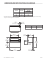
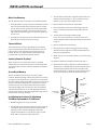
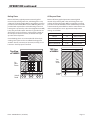
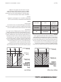
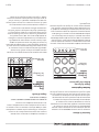
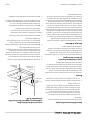
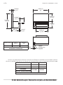
DIMENSIONS AND SPECIFICATIONS, 36E SERIES RANGES
36"
[914mm]
24"
[610mm]
6"
[152mm]
6"
[152mm]
6"
[152mm]
REAR
ELECTRICAL
33-3/4"
[ 857mm]
14-1/2"
[368mm]
6"
[152mm]
36"
[914mm]
30"
[762mm]
1 8"
[457mm]
1 5"
[381mm]
18"
[ 457mm]
63"
[1600mm]
With "DD
"
HI SHELF
31-3/8"
[797mm]
With STD
BACKGUARD
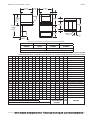
MODEL
TOTAL
kW
3-PHASE
kW PER PHASE
ALL VOLTAGES
NOMINAL AMPERES PER LINE
SINGLE PHASE
THREE PHASE
208V 240V 460V
X-Y Y-Z X-Z 208V 240V 460V X Y Z X Y Z X Y Z
36ER32, 36ER38 21.5 6.5 5 10 103 91 47 69 48 64 61 43 56 31 22 28
36ER32-3 36ER33-88 20.7 6.5 1.2 10 99 88 NA 69 45 60 61 40 53 NA NA NA
36ER33 19.1 6.5 4.2 8.4 92 81 NA 62 45 54 55 40 47 NA NA NA
36ER33-99 18.7 4.2 8 6.5 90 79 NA 45 52 61 40 45 54 NA NA NA
36ER35, 36ER36 18.5 6.5 6 6 89 78 40 53 53 51 46 46 44 24 24 23
36ER39 18.5 6.5 4 8 89 79 40 61 45 50 54 39 45 28 20 23
36ET32, 36ET38 15 5 5 5 72 64 33 42 42 42 37 37 37 19 19 19
36ET/ES32-3, 36ET/ES33-88 14.2 5 4.2 5 68 60 NA 42 39 39 37 34 34 NA NA NA
36ET/ES33 12.6 4.2 4.2 4.2 61 53 NA 35 35 35 31 31 31 NA NA NA
36ET/ES33-99 12.1 4.2 4 4 58 52 NA 35 35 34 31 31 30 NA NA NA
36ET/ES35, 36ET/ES36 12 0 6 6 58 51 26 29 29 51 25 25 44 13 13 23
36ET/ES39 12 4 4 4 58 51 26 34 34 34 30 30 30 15 15 15
36ERC32 20.4 5.4 5 10 98.1 85 NA 65 44 63 56 38 54 NA NA NA
36ERC32-3 19.6 5 4.6 10 94.2 81.7 NA 44 40 61 38 35 53 NA NA NA
36ERC33 18 5 4.6 8.4 86.5 75 NA 56 40 55 49 35 47 NA NA NA
36ERC33-88 19.6 5 4.6 10 94.2 81.7 NA 63 40 61 55 35 53 NA NA NA
36ERC33-99 17.6 8.2 4.4 5 84.6 73.3 NA 56 53 40 48 46 34 NA NA NA
36ERC35 17.4 5 6 6.4 83.7 72.5 NA 52 46 44 45 40 38 NA NA NA
36ERC36 17.4 5.4 6 6 83.6 72.5 NA 48 48 50 42 42 44 NA NA NA
36ERC38 20.4 5 5.4 10 98.1 85 NA 63 44 65 55 38 56 NA NA NA
36ERC39 17.4 5.4 4 8 83.7 72.5 NA 56 40 58 49 34 44 NA NA NA
Note for Model Numbers: ER= Oven Base, ET= Modular TOP, ES=Storage Base, ERC=Convection Oven Base
CLEARANCES
ENTRY TO COMBUSTIBLE WALL
SIDES REAR
1
41-1/4" (1048mm) 36-1/4" (921mm) 3" (76mm) 1/2" (13mm)
1
Rear Clearance for Convection ovens is 2” (51mm)

Part # 1009067 Rev13 (12/04/09) Page 5
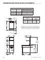
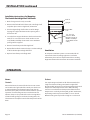
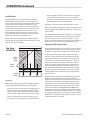
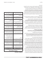
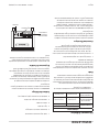
DIMENSIONS AND SPECIFICATIONS, ER36 BROILER
REAR
ELECTRICAL
2-3/4"
[70mm]
28-1/4"
[718mm]
14"
[356mm]
17-1/4"
[413mm]
36"
[914mm]
1-5/8"
[41mm]
18"
[757mm]
11-1/32"
[280mm]
32-1/4"
[819mm]
3-1/2"
[89mm]
ELECTRICAL LOADING CHART: MODEL ER36
VOLTAGE TOTAL kW
NOMINAL AMPERES
PER LINE
SINGLE PHASE
208 7.00 33.7
240 7.00 29.2
460 5.51 12.0
NOTE: When ER36 models are wired independently from the range, they are only available as single phase. Refer to wiring
diagrams for detailed range mount electrical data.
COMBUSTIBLE WALL CLEARANCES
Left Side Right Side Back
6” (152mm) 4-1/2” (114mm) 1/2” (13mm)

Part # 1009067 Rev13(12/04/09)Page 6
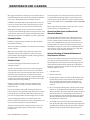
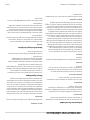
DIMENSIONS AND SPECIFICATIONS, ATTACHMENTS
36"
[914mm]
24"
[610mm]
6"
[152mm]
REAR
ELECTRICAL
INLET
30"
[762mm]
18"
[457mm]
15"
[381mm]
15-9/32"
[388mm]
18"
[457mm]
6"
[152mm]
6"
[152mm]
6"
[152mm]
33-3/4"
[857mm]
18"
[457mm]
63"
[1600mm]
With "DD"
Hi Shelf
31-3/8"
[797mm]
With STD.
Backguard
Modular Top
12" [305mm]
ELECTRICAL LOADING CHART : MODELS 36ES(ET)16 & 36-ES(ET)15
VOLTAGE TOTAL kW
NOMINAL AMPERES PER LINE
SINGLE PHASE
208 6.00 28.8
240 6.00 25.0
460 6.00 13.0
CLEARANCES
ENTRY
TO COMBUSTIBLE
WALL
CRATED UNCRATED SIDES REAR
20-3/4"
(527mm)
18-14"
9464mm)
3"
(76mm)
1/2"
(13mm)
Garland products are not approved or authorized for home or
residential use, but are intended for commercial applications
only. Garland will not provide service, warranty, maintenance
or support of any kind other than in commercial applications.

Part # 1009067 Rev13 (12/04/09) Page 7
GENERAL INFORMATION
Product Information
36 Series Ranges are designed to battery with other 36 Series
equipment.
Construction
Heavy duty modular construction minimizes the use of hard
to clean screws and bolts on exterior of range. Cleaning is
made easier and more complete.
Circuit Breakers
Supplied standard except for open elements. Fuses are used
for open elements.
Grease Troughs
Front and rear, catch excess grease and spillage. Drain into
grease pans located under range top.
Service
Service and maintenance is done completely from the front.
Oven Base
Giant capacity oven is 26 1/2” (667 mm) wide x 29” (736 mm)
deep x 12 1/2” (318 mm) high. Heavy duty thermostat with
pilot light provides temperature control between 200°F
(93°C) and 500°F (290°C). Top element 3 k.W. and bottom
element 3.5 k.W. each controlled by three heat switch for
exibility of heat. One heavy duty rack is standard. Additional
racks are available at extra cost. Exclusive heat ow oven
design eliminates hot spots and gives consistently even oven
temperatures. Aluminum clad steel oven interior reects heat
back to product and ensures long life. Oven door and oven
deck nished in porcelain. Oven door is heavy duty typed
designed to bear in excess of 250 lbs, (113Kg) load. Spring
adjustment is accessible from front of range.
Storage Base
A storage base with stainless steel doors is available.
Modular Top
For mounting on a custom made stand.
Venting
All ranges are supplied with standard 3” (76 mm) high
stainless steel vent riser. Double Deck High Shelf available
in sizes from 18” (476 mm) to 72” (1829 mm) wide. Standard
nish is stainless steel front with brushed chrome splash wall
and aluminum clad back. Optional nish is stainless steel
shelves, sides and back. A satisfactory power ventilator such
as Vent Master properly adapted to the range may be used.
Rating Plate
When corresponding with the factory refer to the particular
unit by the correct model number (including prex and sux
letters and numbers) and the serial or code number. The
rating plate axed to the unit contains this information.
Before attempting the electrical connection, the rating
plate should be checked to ensure that the unit’s electrical
characteristics and the supply electrical characteristics agree.
Unit rating plate is located behind the lower front panel.
Optional extended warranty
Garland,
With a tradition of superior equipment quality and
performance, oers you, our valued customer, an additional
one year limited warranty beyond our standard one year
coverage.
This additional coverage for parts and labor may be
purchased on a new equipment order or up to 60 days after
the equipment purchase. Please contact your Equipment
Dealer or Maintenance & Repair Center (list enclosed) to take
advantage of this exception oer.
Thank you for using Garland products. It is our pleasure to
serve you.

Part # 1009067 Rev13(12/04/09)Page 8
INSTALLATION
Clearances and Setting
CLEARANCES
MODEL TYPE
TO COMBUSTIBLE WALL
SIDES REAR*
Range and Range
Attachments
3" (76mm) 1/2" (13mm)
Broiler with Range 6” (152mm) 1/2” (13mm)
* Rear clearance for convection oven base models is
2” (51mm).
Proper placement of the range will ensure operator
convenience and satisfactory performance. Adequate
clearance must be provided for servicing, ventilation and
proper operation. The range must be kept free and clear of
combustible material.
Legs
All units are shipped with N.S.F. approved legs. These legs
must be installed to provide a minimum clearance of 6”
between the oor and bottom of the unit in order to meet
National Sanitation Foundation requirements.
1. Locate unit in its nal position.
2. Raise the rear and block it. Insert the bullet foot into the
leg cone. Tap with mallet until the bullet foot seats up to
the collar. Unit may now be leveled by adjusting hex head
portion of the bullet foot. Repeat for all four legs.
Electrical Connections
Before attempting the electrical connection, the rating
plate should be checked to ensure that the unit’s electrical
characteristics and the supply electrical characteristics agree.
The Garland 36E series complies with the standards CSA
C222 no. 109-latest edition, the UL197-latest edition and the
NSF #4-latest edition. The installation & connection of this
appliance must comply with the current codes. In Canada-
the Canadian Electrical Code Part 1 and in the USA-The
national Electrical Code.
1. Switch panel size.
2. Overload protection.
3. Wire type.
4. Wire size.
5. Temperature limitations of the wires.
6. Method of connection (Cable, Conduit, etc.)
Wiring Diagram
IMPORTANT: Input voltage and phasing must match the
units voltage and phasing.
A wiring diagram is attached to the main back of each unit.
Visually check all electrical connections. Energize electric
service to units. The range is wired standard for three phase
connections. If it is necessary to change to single phase,
please refer to wiring diagrams. Service and unit voltage
must agree. Unit rating plate is located behind the lower
front panel.
Circuit Breakers and Fuses
Heavy duty circuit breakers and fuses are provided to assure
you many years of safe trouble-free operation. They are
located behind the lower front panel.
Garland
Terminal Bock
Located behind
Panel.
Circuit
Breakers
Fuses

Part # 1009067 Rev13 (12/04/09) Page 9
Main Line Entrance
Two (2) alternate entrance location are provided as follows:
1. Through bottom of range. Center line of bottom entrance
hole is 8 3/4” from left and 5” from front base. If conduit
is used, allow an 8 1/2” extension for units installed with
legs adjusted to 6” height, a 5” extension when legs are
adjusted to a minimum height, a 3” extension when legs
are not used.
2. Through back of range. Center line of back entrance is 11”
from left side and 2” up from base of range.
Terminal Block
The terminal block, as well as grounding lug, is mounted
in fuse compartment behind lower from panel. To remove
panel, loosen screws and lift up and out using louver as
handle. All units are equipped with circuit breakers and
provided with a panel in front of terminal block.
Sanitary Counter Top Seal
When a broiler or “T” Section (Top Section) is installed
without legs on a counter top it must be sealed completely
around base with a silicone sealant in compliance with N.S.F.
Standards.
Assembly of Battery
All units should be placed in their respective battery
positions. Remove packing material. The protective covering
on stainless steel should also be removed. Level each unit to
the oven rack by adjusting legs. Where legs are not used, unit
must be leveled by using shims. Use a spirit level and level
unit four (4) ways; across front and back and front to back
along left and right sides. The two (2) 5/16” hex head bolts
and nuts labeled “Remove and use for Banking” should be
removed and used for joining unit together through ends of
main front top and main back top.
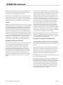
Installation Instructions for Mounting
The ER36 (Salamander) To 36E Series
1. Back of Range must be easily accessible.
2. Install Salamander support brackets to range by slipping
Salamander support brackets into the opening in the
burner box sides so bottom ange of Salamander
support bracket ts over 10-24 stud in range. Securely
fasten with 10-24 hex nut and lock washers.
3. Securely fasten Salamander support brackets at the rear
to burner box sides with 1/4 - 20 x 3/4 slot truss head
machine screws, hex nuts and lock washers.
4. Remove lower front panel from Salamander.
5. Place Salamander on the rear of the Range Lining up
holes in Salamander support brackets with holes on
Range.
6. Securely fasten Salamander to Range with
5/16 - 18 x 1 hex head machine screws, hex nuts and
washers. Replace Salamander lower front panel removed
in step 4.
7. Remove Salamander control panel.
8. The two (2) wires coiled on top right section of range
should be run through hole in back of Salamander and
into wiring compartment.
9. Attach two (2) wires to terminal block per encloses wiring
diagram.
10. Replace Salamander control panel removed in step 7.
11. A burner box back panel, which is installed at the back
of the range, is supplied with the salamander. This panel
covers the exposed back of the burner box where the
mounting brackets are attached. Use the metal machine
screws to secure this panel to the back of the range.
Salamander
Support
Salamander
Bracket
Burner Box
Side
Burner
Back
Salamander
Bracket
INSTALLATION continued

Part # 1009067 Rev13(12/04/09)Page 10
Installation Instructions for Mounting
The Double Deck High Shelf 36E Series
1. Back of range must be easily accessible.
2. Remove the at head bolt “A” from each side of high shelf
only when place next to a high shelf, Salamander.
3. Place backguard, high shelf on the rear of the Range
slipping the support brackets into the opening in the
burner box side.
4. Securely fasten support brackets to the burner box sides
with (4) 1/4 - 20 x 3/4 slot truss head machine screws
or (4) #10B x 1/2 Phillips sheet metal screws. Hardware
package will be supplied.
5. Remove lower front panel of the high shelf.
6. Replace at head bolts removed in step 2 so that each high
shelf is bolted to adjacent high shelf at “A”.
7. Replace lower front panel of high shelf.
INSTALLATION continued
Upright
Burner Box
Side
1/4 - 20 x 3/4
Slot Truss Head
Machine Screws or
#10B x 1/2 Phillips
Sheet Metal Screws
4 Req.
Bolt "A"
Ventilation
An adequate ventilation system is recommended for all
commercial electrical cooking appliances. For further
information please refer to “Vapor Removal From cooking
Equipment” National Fire Protection Association Standards.
OPERATION
Ovens
Controls
On standard units, the controls for the lower oven section
are located on the right end of the switch pane. Each oven
is equipped with top and bottom heating units. Two (2)
three heat, heavy duty reversible switches allow for separate
operation of each heating unit. An oven thermostat and
indicator lamp are also provided for each oven. Regardless
of Switch Settings of Upper and Lower heating Units, the
Thermostat Has Complete Control of the Temperature of the
Oven.
Preheat
Turn top heating unit (Switch at left of thermostat dial) to
“High”. Turn bottom heating unit (Switch at right of the
thermostat dial) to “High.” Set oven thermostat dial to desired
temperature. Pilot lamp will now come “ON,” indicating
oven has not reached desired temperature. When desired
temperature is reached, pilot lamp will go “OFF”. At this time,
top heating switch may be turned “OFF” or set as desired.
Bottom heating unit may be left at “High” or set as desired.

Part # 1009067 Rev13 (12/04/09) Page 11
During preheat period, keep oven door closed. With oven
operating on rated voltage, it will require approximately 18
to 20 minutes to reach 450°F from a cold start.
Personal preferences of dierent operators dictate time and
temperature requirements for various cooking operations.
For this reason, no times or temperatures are suggested here.
If in doubt, consult a good cookbook on volume cooking.
General
Baking or roasting may be done in the oven on the oven rack
provided with each oven. Best baking or roasting results will
be obtained with only one rack of product at a time. Multi-
rack loading will greatly change bake/roast characteristics
and “done” times. Do not bake or roast directly on the oven
bottom. In choosing pans, be sure pan size will allow space
between back, sides and oven door to allow for proper heat
circulation. Personal preferences of dierent chefs and food
service operators dictate temperature and time requirements
for various oven cooking operations. For this reason, no
cooking times or temperatures are suggested here. If in
doubt, consult a good cookbook on volume food service.
Range Base Convection Oven (RC)
As a guide, set oven temperature 25° to 50° lower than called
for in recipes directions using standard or conventional
ovens. Cooking time may be less depending upon the
product you are preparing. 2% to 5% is a general rule.
Product should be watched the rst time it is prepared.
Cooking time and oven temperature will vary depending
upon such factors as size of load, temperature of product,
and mixture of recipe, particularly moisture. When you
have established satisfactory time and temperature for our
products, record them on a chart and keep as a reference
guide.
OPERATION continued
Preheat oven thoroughly before use. To reach 350°F takes
approximately 20 minutes. For optimum results oven should
be preheated for 30 minutes to allow for thorough heat
saturation. The load should be centered on the oven racks
to allow for proper heat circulation around the sides. Load
size – the oven will hold three (3) 18” x 26” sheet pans, six
(6) 12” x 20” x 2.5” steam table pans or one (1) 17.75” x 25.75”
roast pan. Never place pans directly on the oven bottom.
Always use the lowest rack position which will allow the
air to circulate within the oven cavity. Load and unload
food as quickly as possible to prevent an excessive drop
in temperature. Avoid using warped pans since level pans
bake more evenly. Do not use a deep pan for shallow cakes,
cookies, etc, as circulation across the surface is essential for
even cooking and browning. To prevent excessive shrinkage,
roast meats at a low temperature (250° to 325°F)
When rethermalizing frozen products preheat the oven 50°
higher than cooking temperature to compensate for heat
loss during and after loading. Thermostat must be returned
to cooking temperature after loading.
Range Base Convection Oven Operation
Activate the power switch to the cook position. Set the fan
speed switch to the desired fan speed. Set oven thermostat
to the desired oven temperature. Allow 20 to 30 minutes to
preheat.
When nished using the oven it should be cooled below
150° before shutting down. Turn the power switch to “cool
Down” and open the oven door. Allow fan to operate for
approximately 30 minutes. To shut down the oven turn the
thermostat and the power switch to the o position.
CAUTION: Motor must operate during cooking cycle. Failure
to do so will shorten motor life!
We recommend, at the end of a bake or roast period, when
the oven will be idle for any period of time to set the oven
thermostat to the lowest temperature setting and allow the
oven to operate. By doing this, the oven motor will keep
itself cool by operating and you will save preheat time for
next ovens’ use. If this procedure is not desirable than we
recommend that the oven be cooled down below 150°F
between baking or roasting periods.

Part # 1009067 Rev13(12/04/09)Page 12
OPERATION continued
Problem / Solution
Heavy Duty Range Convection Oven
Problem Solution
Cakes are dark on the sides
and not done in the center
Lower oven temperature
Cakes edges are too brown Reduce number of pans or
lower oven temperature
Cakes have light outer color Raise temperature
Cake settles slightly in the
center
Bake longer or raise oven
temperature slightly.
Do not open doors too
often or for long periods
Cake ripples Overloading pans or batter
is too thin
Cakes are too coarse Lower oven Temperature
Pies have uneven color pans Reduce number of pies per
rack or eliminate use of
bake pans
Cupcakes crack on top Lower oven temperature
Meats are browned and not
done in center
Lower temperature and
roast longer.
Meats are well done and
browned
Reduce time. Limit amount
of moisture
Meats develop hard crust Reduce temperature or
place pan of water in oven.
Rolls have uneven color Reduce number of size
pans.
Motor Care
The motor on your Garland range base convection is
maintenance free since it is constructed with self-lubricating
sealed ball bearing. It is designed to provide durable service
when treated with ordinary care. Be sure to follow the cool
down procedure as mentioned in the above paragraphs or
to lower the oven temperature during idle periods. Failure
to follow the prescribe procedure may not void warranties,
but, may cause your oven motor to fail when you need it the
most.
Top Sections
Cooking Top – Open Type Burners
High speed tubular heating units are each provided with a
three heat switch. Each high speed tubular heating unit is
rated a 2.1 k.w. designed to give speed and exibility where
sauce pans are used. It should be pointed out that these are
NOT designed or intended for use in heavy (stock pot) duty
service. Use of large stock pots will severely damage surface
elements. It is recommended that only utensils of 8” to 10”
diameter (with a capacity no greater than 1 U.S. gallon), be
used.
Surface heating units should not be left on high heat if not
covered by a cooking utensil. Turn switch to “O” or “Low”
when units are idling. Failure to do this will shorten the life of
the surface heating elements.
NEVER USE LARGE STOCK POTS ON SURFACE HEATING
ELEMENTS!
Top View
of 36ER33
Six
Heating
Units
Switch
Panel

Part # 1009067 Rev13 (12/04/09) Page 13
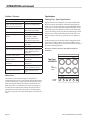
Boiling Plates
Remove all factory applied protective material (gelled
mineral oil) by washing with a hot, mild detergent or soap
solution, then dry thoroughly. Before using follow seasoning
procedure in the Griddle Plate Section. All Boiling Plates are
provided with separate front and back heating units. Each
heating unit is operated by a three heat (High-Med-Low-O),
heavy duty reversible switch. Switches are grounded in sets
of two (2) for each 12” of plate. In each group, the switch at
the left operates the front section, the switch at the right
operates the back position.
General Boiling plates are recommended for all stock pot
cooking, These plates are the most exible boiling plates
available. The 36” (914 mm) x 24” (610 mm) steel top, has six
heat zones. Total top input of 12.0 k.W.
Switch
Panel
Six
Heat
Zones
Top View
of 36ER39
OPERATION continued
All Purpose Plates
Remove all factory applied protective material (gelled
mineral oil) by washing with a hot, mild detergent or soap
solution, then dry thoroughly. Before using follow seasoning
procedure in the Griddle Plate Section. Each All Purpose Plate
is thermostatically controlled from 250°F to 700°F. thermostat
dials are marked from 1 to 10. Approximate temperatures
settings are as follows.
MODE DIAL SETTING TEMPERATURE
Simmer 1-2 250°F to 300°F
Fry 2-5 300°F to 450°
Boil 5-8 450° to 600°F
Pan Fry & Fast boil 8-10 600°F to 700°
TOP View
of 36ER36
Two
Heat
Zones
Switch
Panel

Part # 1009067 Rev13(12/04/09)Page 14
Griddle Plates
All steel griddle plates are controlled by thermostats
permitting separate temperatures to be maintained at
any time. Heavy Griddle work recommended for quantity
cooking where even temperature and fast recovery is
required. Top plate has welded 2 1/2” (64 mm) high side
splash guards. Griddle Top: One 36” (914 mm) x 24” (610
mm) polished steel plate, has three heat zones each
thermostatically controlled from 150°F (38°C) to 450°F
(232°C) with indicator lamp. Total top input of 15.0 k.W.
preheats to 350°F (180°C) in eight minutes.
Remove all factory applied protective material (gelled
mineral oil) by washing with a hot, mild detergent or soap
solution, then dry thoroughly.
Three
Heat
Zones
Switch
Panel
Grease
Drains
Top View
of 36ER38
Seasoning
Before being used for the rst time, all griddles must be
“Seasoned.” The following method is recommended:
• Apply a thin coat of cooking oil to the griddle surface,
about one ounce per square foot of griddle surface.
Spread over the entire griddle surface with a cloth to
create a thin lm. Wipe o any excess oil with a cloth.
• Turn on all thermostats, set at 150°F setting. Some
discoloration will occur when heat is applied to steel.
• Heat the griddle slowly for 15 to 20 minutes. Then wipe
away oil. Repeat the procedure 2 to 3 times until the
griddle has a slick, mirror like nish. Do this until you have
reached the desired cooking temperature.
Important: Do not attain 450°F during “break-in” period.
Note: Steel griddle surface will tone (blue discoloration) from
heat. This toning will not diminish function or operation and
is not a defect.
The griddle will not require reseasoning if it is used properly.
If the griddle is over heated and product begins to stick to
the surface it may be necessary to repeat the seasoning
process again. If the griddle is cleaned with soap and water it
will be necessary to reseason the griddle surface again.
Operation of Broiling Section
Heavy Duty Electric Broilers are available in single or double
deck model mounted on an oven or storage base. It is also
available as a single deck or double deck modular section.
Broiling Compartments has broiler rack in each section
riding in a spring counter-balanced raising and lowering
mechanism, adjustable to 15 positions. The rack may be
raised to with 1/2” of the heating elements. The 24” by 22-
5/8” broil rack, with attached drip shield, rolls in and out
easily on six roller bearings. A lock stop prevents the rack
from accidentally being pulled out of the tracks, yet the
rack and drip shield may be readily removed for cleaning.
The large porcelain enameled grease pan is removed for
cleaning. Bae spoilers within the pane prevent spillage
during removal.
Heating Elements: Two inconel sheathed heating element
packages are provided; one service the rear half of the
broiling compartment, the other the front half. The element
package for the front half of the broiling compartment is
controlled by a three position heat heavy duty reversible
switch mounted at the bottom of the panel. Each switch
adjusts from full OFF to HIGH, MEDIUM and LOW modes.
Each broiler section is provided with a pilot indicator lamp
mounted in the control panel. When the lamp is lit, it signals
that energy is being applied to the elements. Each element
package has a maximum rating of 6 k.W. providing a 12 k.W.
maximum total for each section
OPERATION Continued

Part # 1009067 Rev13 (12/04/09) Page 15
MAINTENANCE AND CLEANING
We suggest maintenance and repairs to be performed by an
Garland Authorized Service Agent. The listing provided with
your range is titled “Maintenance and Repair Centers”.
CAUTION: Remember! Water and electricity do not mix, do
not use excessive water, heavily soaked sponges or rags to
clean switch panels or areas near electrical connections!
NOTE: RUST can form on raw steel and cast iron parts. Be
sure parts are dried thoroughly after cleaning. In warm, moist
environments, raw parts may require protection. Wipe down
with light coating of oil, rust inhibitor, or polish as applicable.
Painted Finishes
Establish a regular cleaning schedule. Any spills should be
wiped o immediately.
The oven should be permitted to cool down before cleaning
exterior surfaces.
Wipe exposed, cleanable surface when cool with a mild
detergent and hot water. Stubborn residue spots may be
removed with a light weight non metallic scouring pad. Dry
thoroughly with a clean cloth.
Stainless Steel
For routine cleaning just wash with a hot water and
detergent solution.
Stainless steel should be cleaned using a mild detergent, a
soft cloth and hot water. If necessary to use a nonmetallic
scouring pad, always rub in the direction of the grain in the
metal to prevent scratching. Use a water based stainless
cleaner (Drakett Twinkle), if you want a high shine. Wash just
a small area at a time or the water will evaporate leaving the
chemicals behind causing streaking.
Rinse the washed area with a clean sponge dipped in a
sanitizing solution and wipe dry with a soft clean cloth
before it can dry.
Use a paste (of water and a mild scouring powder) if you
have to, but never rub against the grain. All stainless steel has
been polished in one direction. Rub with the polish lines to
preserve the original nish. Then thoroughly rinse as before.
To prevent ngerprints there are several stainless steel
polishes on the market that leave an oily or waxy lm. Do not
use on surfaces that will be in contact with food.
Stainless steel may discolor if overheated. These stains can
usually be removed by vigorous rubbing with a scouring
powder paste.
Use only stainless steel, wood or plastic tools if necessary
to scrape o heavy deposits of grease and oil. Do not use
ordinary steel scrapers of knives as particles of the iron may
become imbedded and rust. STEEL WOOL SHOULD NEVER BE
USED.
Either a typical bleach solution or hot water can be used to
sanitize stainless steel with out harm.
Oven Inner Door Liner and Oven Deck
(Porcelain Enamel)
The porcelain Oven Inner door Liner and Oven Deck can
be cleaned with oven cleaners such as “Easy-O”, or “Dow
Cleaner”. Follow product manufacture’s instructions for
proper use. CAUTION: Do not get any oven cleaner on any
painted surface, the oven cleaner will remove the paint!
CAUTION: Do not get any oven cleaner on Aluminized Steel
Inner Surfaces, it will cause the surface to turn a deep blue
color and may mar the aluminized surface.
Interior Cleaning of Standard Aluminized
Steel Interior Surfaces.
The oven sides and top linings are formed of heavy gauge
steel with an aluminum fused into its surface to provide
for the reectance of heat back to the food being prepared
and to virtually eliminate the possibility of rust formation.
Establish a regular cleaning schedule or wipe o on the same
day when spillovers occur.
1. Cool down oven.
2. Remove oven racks.
3. Lift rack guides on either side of oven o of holders, pull
the top away from the cavity wall, when it’s cleared the
clips push down and remove. Racks and guides may
be run through dishwasher while oven cavity is being
cleaned.
4. Use a concentrated detergent on a plastic pad to remove
burned on soil. Do Not Use Steel Wool, Oven Cleaner Or
Abrasive Powders. These will remove the aluminum. Rinse
with warm water on a soft cloth. Be sure to remove all
traces of detergent. Any discoloration which may remain
after the soil build-up has been removed will not aect
the performance of the oven.
5. To reinstall reverse procedure. Place the bottom of the
rack guide against the cavity wall. Keeping the top pulled
away from the wall lift up. Push the top of the rack guide
against the wall and push down locking it into place.

Part # 1009067 Rev13(12/04/09)Page 16
Cleaning and Care of
Top Surface Heating Burners
Surface units may be raised to permit removal of spillover
bowls under the surface burners. Spillover bowls may be
cleaned, wiped dry and replaced. Drip trays under the front
control panel may also be removed, washed, rinsed, wiped
dry and replaced. Cooking top may be wiped with a damp
cloth using a mild detergent and wary water. You may also
follow pervious instructions for “cleaning Stainless Steel
Exterior.”
Cleaning of Griddle, All Purpose Plates and
Boil Plates
To produce evenly cooked, perfectly browned griddle
products, keep griddle free from carbonized grease.
Carbonized grease on the surface hinders the transfer of
heat from the griddle surface to food product. This results
in uneven browning and loss of cooking eciency, and
worst of all, carbonized grease tends to cling to the griddle
foods, giving them a highly unsatisfactory and unappetizing
appearance. To keep the griddle clean and operating at peak
performance, follow these simple instructions.
A. After Each Use clean griddle thoroughly with a grill
scraper or spatula. Wipe o any excess debris left from
cooking process.
B. Once A Day clean griddle surface with a grill brick and
grill pad. Remove grease container and clean thoroughly,
in same manor as any ordinary cooking utensil.
MAINTENANCE AND CLEANING continued
C. Once A Week clean griddle surface thoroughly. If
necessary, use a grill stone or grill pad over the griddle
surface. Rub with grain of the metal while still warm. A
detergent may be use on the plate surface to help clean
it, but care must be taken to be sure it is thoroughly
removed. After removal of detergent, the surface of the
plate should be covered with a thin lm of oil to prevent
rusting. To remove discolorations, use a non-abrasive
cleaner. Before re-using the griddle must be reseasoned.
Keep griddle drain tube to grease container clear at all
times on those models without side grease container.
CAUTION: This griddle plate is steel, but the surface is
relatively soft and can be scored or dented by careless use
of spatula. Be careful not to dent, scratch, or gouge the plate
surface. This will cause food to stick in those areas. Also, note
since this is a steel griddle if a light coating of oil is not always
present rust will develop on unexposed areas.
Broiler Section
Broil rack, rack carriage and drip pan may be removed for
cleaning.
Lift broil rack out of carriage. Pull rack carriage forward to
rack stops and raise. Carriage may now be pulled out of
tracks. Raise and pull grease pan forward and out. Entire
interior of broiler may now be cleaned. After washing and
drying, reassemble parts by reversing previous steps.
After cleaning Boil Plates, All Purpose Plates, Griddles,
Tubular Heating Units, Ovens and Broilers, wash front and
back grease troughs and drip trays with hot, mild detergent
or soap solution and dry thoroughly.

Part # 1009067 Rev13 (12/04/09) Page 17
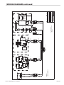
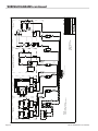
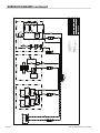
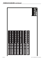
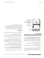
WIRING DIAGRAMS
36ER-ET-ES 208V/240V
1
36E SERIES
SEPT 22,2002NANB
31
4514760
875W
1125W
875W
1125W
1500W
1500W
1500W
2000W
H3
H1
H2
H6
H4
H5
o6
o5
o4
o3o2o1
212019 22 23 24
16
15
18
17
5000W
G1
G2
G4
G3
11
12
o7
o8
S2
13
14
o7
o8
S1
S3 S4
98
o9
o9
G5
3
5
4
6
12
5
3
6
4
12
5
3
6
4
12
3
5
1
4
6
2
4
6
3
5
21
34
56
12
P3
1
P1
2
P2
43
P3 P1
123
P2
4
P3 P1
123
P2
4
UPPER OVEN ELEMENTS LOWER OVEN ELEMENTS
4321
P3 P1 P2
4321
P3 P1 P2
4KW BOIL TOP
1
12
2COM
COM
THERMOSTAT
THERMOSTAT
30A
40A
40A
30A 30A
40A
ER 7kW
SALAMANDER
40A
40A
30A
40A
P3
1
P1 P2
324
OPEN TOP GRIDDLE-ALL PURPOSE TOP OVEN
200-550F
TB
LEFT
CENTER
RIGHT
RIGHT
CENTER
LEFT
CENTER
RIGHT
LEFT
TO TERMINAL BLOCK
(See page 2 for terminal block connection)
RIGHT
LEFT
CENTER
CENTER
RIGHT
LEFT
RIGHT
CENTER
LEFT
INNER
OUTER
INNER
OUTER
:
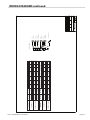
ALL DIMENSIONS ARE IN INCHES
TOLERANCE ±0.015" UNLESS OTHERWISE SPECIFIED
:
:
:
TITLE:
DATE
SCALE
DR.
SHT OF
CHK. BY
REV
REV.#
DATE
DR.DESCRIPTION
REVISIONS
MODEL:
36ER32; 36ER32-3; 36ER33;
36ER33-88;36ER33-99;36ER38;36ER39
36ES32; 36ES32-3; 36ES33; 36ES33-88;
36ES33-99;36ES38;36ES39;36ES17
36ET32; 36ET32-3; 36ET33; 36ET33-88;
36ET33-99;36ET38;36ET39;36ET17

Part # 1009067 Rev13(12/04/09)Page 18
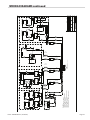
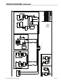
WIRING DIAGRAMS continued
36ER-ET-ES 208V/240V
1
36E SERIES
SEPT 22,2002NANB
32
4514760
3 PHASE CONNECTION
SINGLE PHASE CONNECTION
NO SALAMANDER
WITH SALAMANDER
E2
S2
E1
4
6
2
3
9
S1
5
1
8
E2
E1
S2
6
4
2
S1
3
5
1
E2
E1
4
6
5
3
2
1
E2
S2
E1
S1
4
6
2
9
5
3
8
1
E2
E1
4
2
2
5
S2
S1
1
3
TO CIRCUIT BREAKER PANEL
TO CONTROL PANEL
SALAMANDER
TOP LEFT
TOP CENTER
TOP RIGHT
OVEN
OVEN
TOP LEFT
TOP CENTER
TOP RIGHT
SALAMANDER
TO CIRCUIT BREAKER PANEL
TO CONTROL PANEL
TOP LEFT
TOP CENTER
TOP RIGHT
TOP LEFT
TOP CENTER
TOP RIGHT
SALAMANDER
SALAMANDER
TOP RIGHT
TOP CENTER
TOP RIGHT
TO CIRCUIT BREAKER PANEL
TO CONTROL PANEL
TOP CENTER
TO CIRCUIT BREAKER PANEL
TO CONTROL PANEL
SALAMANDER
TOP LEFT
TOP LEFT
TOP CENTER
SALAMANDER
TOP CENTER
TOP RIGHT
TOP LEFT
OVEN
TOP RIGHT
OVEN
TOP LEFT
TO CIRCUIT BREAKER PANEL
TO CONTROL PANEL
TOP CENTER
TOP RIGHT
TOP LEFT
TOP RIGHT
SALAMANDER
TOP LEFT
TOP CENTER
SALAMANDER
36ER32; 36ER32-3; 36ER33; 36ER33-88;
36ER33-99;36ER38;36ER39
G
Z
Y
X
36ER32; 36ER32-3; 36ER33; 36ER33-88;
36ER33-99;36ER38;36ER39
G
X
Z
Y
36ES32; 36ES32-3; 36ES33; 36ES33-88;
36ES33-99;36ES38;36ES39
36ET32; 36ET32-3; 36ET33; 36ET33-88;
36ET33-99;36ET38;36ET39
G
Z
Y
36ES32; 36ES32-3; 36ES33; 36ES33-88;
36ES33-99;36ES38;36ES39;36ES17
36ET32; 36ET32-3; 36ET33; 36ET33-88;
36ET33-99;36ET38;36ET39;36ET17
X
G
Z
Y
X
36ES32; 36ES32-3; 36ES33; 36ES33-88;
36ES33-99;36ES38;36ES39
36ET32; 36ET32-3; 36ET33; 36ET33-88;
36ET33-99;36ET38;36ET39
G
Z
Y
X
:
ALL DIMENSIONS ARE IN INCHES
TOLERANCE ±0.015" UNLESS OTHERWISE SPECIFIED
:
:
:
TITLE:
DATE
SCALE
DR.
SHT OF
CHK. BY
REV
REV.#
DATE
DR.DESCRIPTION
REVISIONS

Part # 1009067 Rev13 (12/04/09) Page 19
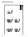
36ER-ET-ES 208V/240V
1
36E SERIES
SEPT 22,2002NANB
33
4514760
:
ALL DIMENSIONS ARE IN INCHES
TOLERANCE ±0.015" UNLESS OTHERWISE SPECIFIED
:
:
:
TITLE:
DATE
SCALE
DR.
SHT OF
CHK. BY
REV
REV.#
DATE
DR.DESCRIPTION
REVISIONS
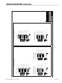
MODEL VOLTAGE TOTAL KW
LOADING PER PHASE AMPERAGE
X-Y X-Z Y-Z 1 Phase X Y Z
36 ER 32
208 21.5 6.5 10 5 103.4 69.2 48.0 63.6
240 21.5 6.5 10 5 89.6 60.0 41.6 55.1
36 ER 32 SAL
208 28.5 6.5 10 12 137.0 69.2 78.2 91.7
240 28.5 6.5 10 12 118.8 60.0 67.7 79.5
MODEL VOLTAGE TOTAL KW
LOADING PER PHASE AMPERAGE
X-Y X-Z Y-Z 1 Phase X Y Z
36 ER 32-3
208 20.7 6.5 10 4.2 99.5 69.2 44.9 60.7
240 20.7 6.5 10 4.2 86.3 60.0 38.9 52.6
36 ER 32-3 SAL
208 27.7 6.5 10 11.2 133.2 69.2 74.6 88.3
240 27.7 6.5 10 11.2 115.4 60.0 64.6 76.5
MODEL VOLTAGE TOTAL KW
LOADING PER PHASE AMPERAGE
X-Y X-Z Y-Z 1 Phase X Y Z
36 ER 33
208 19.1 6.5 8.4 4.2 91.8 62.2 44.9 53.4
240 19.1 6.5 8.4 4.2 79.6 53.9 38.9 56.3
36 ER 33 SAL
208 26.1 6.5 8.4 11.2 125.5 62.2 74.6 81.9
240 26.1 6.5 8.4 11.2 108.8 53.9 64.6 71.0
MODEL VOLTAGE TOTAL KW
LOADING PER PHASE AMPERAGE
X-Y X-Z Y-Z 1 Phase X Y Z
36 ER 33-88
208 20.7 6.5 10 4.2 99.5 69.2 44.9 60.7
240 20.7 6.5 10 4.2 86.3 60.0 38.9 52.6
36 ER 32 SAL
208 27.7 6.5 10 11.2 133.2 69.2 74.6 88.3
240 27.7 6.5 10 11.2 115.4 60.0 64.6 76.5
MODEL VOLTAGE TOTAL KW
LOADING PER PHASE AMPERAGE
X-Y X-Z Y-Z 1 Phase X Y Z
36 ER 33-99
208 18.7 6.5 8 4.2 89.9 60.5 44.9 51.6
240 18.7 6.5 8 4.2 77.9 52.4 38.9 44.7
36 ER 33-99 SAL
208 25.7 6.5 8 11.2 123.6 60.5 74.6 80.3
240 25.7 6.5 8 11.2 107.1 52.4 64.6 69.6
MODEL VOLTAGE TOTAL KW
LOADING PER PHASE AMPERAGE
X-Y X-Z Y-Z 1 Phase X Y Z
36 ER 38
208 21.5 6.5 10 5 103.4 69.2 48.0 63.6
240 21.5 6.5 10 5 89.6 60.0 41.6 55.1
36 ER 38 SAL
208 28.5 6.5 10 12 137.0 69.2 78.2 91.7
240 28.5 6.5 10 12 118.8 60.0 67.7 79.5
MODEL VOLTAGE TOTAL KW
LOADING PER PHASE AMPERAGE
X-Y X-Z Y-Z 1 Phase X Y Z
36 ER 39
208 18.5 6.5 8 4 88.9 60.5 44.1 50.9
240 18.5 6.5 8 4 77.1 52.4 38.2 44.1
36 ER 39 SAL
208 25.5 6.5 8 11 122.6 60.5 73.7 79.4
240 25.5 6.5 8 11 106.3 52.4 63.8 68.8
MODEL VOLTAGE TOTAL KW
LOADING PER PHASE AMPERAGE
X-Y X-Z Y-Z 1 Phase X Y Z
36 ES 17
36 ET 17
208 10 5 5 0 48.1 41.6 24.0 24.0
240 10 5 5 0 41.7 36.1 20.8 20.8
MODEL VOLTAGE TOTAL KW
LOADING PER PHASE AMPERAGE
X-Y X-Z Y-Z 1 Phase X Y Z
36 ES 32
36 ET 32
208 15 5 5 5 72.1 41.6 41.6 41.6
240 15 5 5 5 62.5 36.1 36.1 36.1
36 ES 32 SAL
36 ET 32 SAL
208 22 7 5 10 105.8 50.2 71.1 63.6
240 22 7 5 10 91.7 43.5 61.7 55.1
MODEL VOLTAGE TOTAL KW
LOADING PER PHASE AMPERAGE
X-Y X-Z Y-Z 1 Phase X Y Z
36 ES 32-3
36 ET 32-3
208 14.2 5 5 4.2 68.3 41.6 38.4 38.4
240 14.2 5 5 4.2 59.2 36.1 33.2 33.2
36 ES 32-3 SAL
36 ET 32-3 SAL
208 21.2 7 5 9.2 101.9 50.2 67.7 60.0
240 21.2 7 5 9.2 88.3 43.5 58.6 52.0
MODEL VOLTAGE TOTAL KW
LOADING PER PHASE AMPERAGE
X-Y X-Z Y-Z 1 Phase X Y Z
36 ES 33
36 ET 33
208 12.6 4.2 4.2 4.2 60.6 35.0 35.0 35.0
240 12.6 4.2 4.2 4.2 52.5 30.3 30.3 30.3
36 ES 33 SAL
36 ET 33 SAL
208 19.6 7 4.2 8.4 94.2 47.1 64.2 53.4
240 19.6 7 4.2 8.4 81.7 40.8 55.6 46.3
MODEL VOLTAGE TOTAL KW
LOADING PER PHASE AMPERAGE
X-Y X-Z Y-Z 1 Phase X Y Z
36 ES 33-88
36 ET 33-88
208 14.2 5 5 4.2 68.3 41.6 38.4 38.4
240 14.2 5 5 4.2 59.2 36.1 33.2 33.2
36 ES 33-88 SAL
36 ET 33-88 SAL
208 20.4 7 4.2 9.2 98.1 47.1 67.7 57.1
240 20.4 7 4.2 9.2 85.0 40.8 58.6 49.5
MODEL VOLTAGE TOTAL KW
LOADING PER PHASE AMPERAGE
X-Y X-Z Y-Z 1 Phase X Y Z
36 ES 33-99
36 ET 33-99
208 12.2 4 4 4.2 58.7 33.3 34.1 34.1
240 12.2 4 4 4.2 50.8 28.9 29.6 29.6
36 ES 33-99 SAL
36 ET 33-99 SAL
208 19.2 7 4 8.2 92.3 46.4 63.4 51.8
240 19.2 7 4 8.2 80.0 40.2 54.9 44.9
MODEL VOLTAGE TOTAL KW
LOADING PER PHASE AMPERAGE
X-Y X-Z Y-Z 1 Phase X Y Z
36 ES 38
36 ET 38
208 15 5 5 5 72.1 41.6 41.6 41.6
240 15 5 5 5 62.5 36.1 36.1 36.1
36 ES 38 SAL
36 ET 38 SAL
208 22 7 5 10 105.8 50.2 71.1 63.6
240 22 7 5 10 91.7 43.5 61.7 55.1
MODEL VOLTAGE TOTAL KW
LOADING PER PHASE AMPERAGE
X-Y X-Z Y-Z 1 Phase X Y Z
36 ES 39
36 ET 39
208 12 4 4 4 57.7 33.3 33.3 33.3
240 12 4 4 4 50.0 28.9 28.9 28.9
36 ES 39 SAL
36 ES 39 SAL
208 19 7 4 8 91.3 46.4 62.5 50.9
240 19 7 4 8 40.2 79.2 54.2 44.1
WIRING DIAGRAMS continued

Part # 1009067 Rev13(12/04/09)Page 20
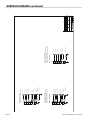
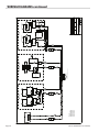
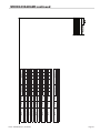
WIRING DIAGRAMS continued
36ER 208V/240V 18"SECTION
1
36E SERIES
SEPT 22,2002NANB
31
4514761
1400W
1600W
1400W
1600W
1500W
1500W
1500W
2000W
B3
B1
B2
B6
B4
B5
2019 22 23 24
16
15
18
17
1400W
A3
A4
A7
A5
11
12
S2
13
14
B7
B8
S1
S3 S4
98
1600W
1600W
1400W
A1 A2
21
A6
34
12
3
1
4
2
2
43
1
2
43
1
P3
1
P1
2
P2
4
3
P1P3
12
P2
43
ALL PURPOSE TOP
P3
1
P1
2
P2
43
UPPER OVEN ELEMENTS
LOWER OVEN ELEMENTS
4321
P3 P1 P2
BOIL TOP
THERMOSTAT
THERMOSTAT
40A 40A 40A40A
ER 7kW
SALAMANDER
40A40A40A40A
OVEN
TO TERMINAL BLOCK
(See page 2 for terminal block connection)
200-550F
TB
RIGHT
LEFT
RIGHT
LEFT
LEFT
RIGHT
LEFT
RIGHT
OUTER
INNER
OUTER
INNER
:
ALL DIMENSIONS ARE IN INCHES
TOLERANCE ±0.015" UNLESS OTHERWISE SPECIFIED
:
:
:
TITLE:
DATE
SCALE
DR.
SHT OF
CHK. BY
REV
REV.#
DATE
DR.DESCRIPTION
REVISIONS
MODEL:
36ER35 36ER36
36ET35 36ET36
36ES35 36ES36
36ET15 36ET16
36ES15 36ES16
La page est en cours de chargement...
La page est en cours de chargement...
La page est en cours de chargement...
La page est en cours de chargement...
La page est en cours de chargement...
La page est en cours de chargement...
La page est en cours de chargement...
La page est en cours de chargement...
La page est en cours de chargement...
La page est en cours de chargement...
La page est en cours de chargement...
La page est en cours de chargement...
La page est en cours de chargement...
La page est en cours de chargement...
La page est en cours de chargement...
La page est en cours de chargement...
La page est en cours de chargement...
La page est en cours de chargement...
La page est en cours de chargement...
La page est en cours de chargement...
La page est en cours de chargement...
La page est en cours de chargement...
La page est en cours de chargement...
La page est en cours de chargement...
La page est en cours de chargement...
La page est en cours de chargement...
La page est en cours de chargement...
La page est en cours de chargement...
La page est en cours de chargement...
La page est en cours de chargement...
La page est en cours de chargement...
La page est en cours de chargement...
La page est en cours de chargement...
La page est en cours de chargement...
La page est en cours de chargement...
La page est en cours de chargement...
La page est en cours de chargement...
La page est en cours de chargement...
La page est en cours de chargement...
La page est en cours de chargement...
-
 1
1
-
 2
2
-
 3
3
-
 4
4
-
 5
5
-
 6
6
-
 7
7
-
 8
8
-
 9
9
-
 10
10
-
 11
11
-
 12
12
-
 13
13
-
 14
14
-
 15
15
-
 16
16
-
 17
17
-
 18
18
-
 19
19
-
 20
20
-
 21
21
-
 22
22
-
 23
23
-
 24
24
-
 25
25
-
 26
26
-
 27
27
-
 28
28
-
 29
29
-
 30
30
-
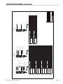 31
31
-
 32
32
-
 33
33
-
 34
34
-
 35
35
-
 36
36
-
 37
37
-
 38
38
-
 39
39
-
 40
40
-
 41
41
-
 42
42
-
 43
43
-
 44
44
-
 45
45
-
 46
46
-
 47
47
-
 48
48
-
 49
49
-
 50
50
-
 51
51
-
 52
52
-
 53
53
-
 54
54
-
 55
55
-
 56
56
-
 57
57
-
 58
58
-
 59
59
-
 60
60


Garland 36ER32 Owner Instruction Manual
- Catégorie
- Fours
- Taper
- Owner Instruction Manual
dans d''autres langues
- English: Garland 36ER32
Documents connexes
-
Garland E20 Series Owner Instruction Manual
-
U.S. Range E20 Series spécification
-
-
Garland GIR36C Mode d'emploi
-
Garland Enodis UIR60 Manuel utilisateur
-
-
Garland GF24-T Mode d'emploi
-
-
Garland XG24CE Mode d'emploi
-
Autres documents
-
Buffalo CD679 Le manuel du propriétaire
-
ROLLER GRILL SEM 800 PDS Instructions for Use and Installation
-
Vulcan 36ESB C36ESB Salamander Broiler Le manuel du propriétaire
-
-
-
Salamander Designs FPS Series Manuel utilisateur
-
Vulcan C36ESB Manuel utilisateur
-
Vulcan EV36S-4FP12G Le manuel du propriétaire
-
Lang LG-48M Fiche technique
-
RM FTR 704 G Instructions For Installation And Use Manual