Garland E20 Series Owner Instruction Manual
- Taper
- Owner Instruction Manual

Part # 1382669 Rev 1 (09/03/09) Page 1
Users are cautioned that maintenance and repairs must be performed by a Garland authorized service agent
using genuine Garland replacement parts. Garland will have no obligation with respect to any product that has been
improperly installed, adjusted, operated or not maintained in accordance with national and local codes or installation
instructions provided with the product, or any product that has its serial number defaced, obliterated or removed,
or which has been modified or repaired using unauthorized parts or by unauthorized service agents.
For a list of authorized service agents, please refer to the Garland web site at http://www.garland-group.com.
The information contained herein, (including design and parts specifications), may be superseded and is subject
to change without notice.
GARLAND COMMERCIAL INDUSTRIES, LLC
185 East South Street
Freeland, Pennsylvania 18224
Phone: (570) 636-1000
Fax: (570) 636-3903
GARLAND COMMERCIAL RANGES, LTD.
1177 Kamato Road, Mississauga, Ontario L4W 1X4
CANADA
Phone: 905-624-0260
Fax: 905-624-5669
Enodis
U
Swallowe
Telephone
:
Fax: 081-8
4
Part # 1382669 Rev 1 (09/03/09) © 2005Garland Commercial Industries, LLC
FOR YOUR SAFETY:
DO NOT STORE OR USE GASOLINE
OR OTHER FLAMMABLE VAPORS OR
LIQUIDS IN THE VICINITY OF
THIS OR ANY OTHER
APPLIANCE
WARNING:
IMPROPER INSTALLATION, ADJUSTMENT,
ALTERATION, SERVICE OR MAINTENANCE
CAN CAUSE PROPERTY DAMAGE, INJURY,
OR DEATH. READ THE INSTALLATION,
OPERATING AND MAINTENANCE
INSTRUCTIONS THOROUGHLY
BEFORE INSTALLING OR
SERVICING THIS EQUIPMENT
PLEASE READ ALL SECTIONS OF THIS MANUAL
AND RETAIN FOR FUTURE REFERENCE.
THIS PRODUCT HAS BEEN CERTIFIED AS
COMMERCIAL COOKING EQUIPMENT AND
MUST BE INSTALLED BY PROFESSIONAL
PERSONNEL AS SPECIFIED.
IN THE COMMONWEALTH OF MASSACHUSETTS
THIS PRODUCT MUST BE INSTALLED BY A
LICENSED PLUMBER OR GAS FITTER. APPROVAL
NUMBER: G-1-07-05-28
For Your Safety:
Post in a prominent location, instructions to be
followed in the event the user smells gas. This
information shall be obtained by consulting
your local gas supplier.
INSTALLATION AND
OPERATION MANUAL
GARLAND INFRA-RED SALAMANDER BROILERS AND
INFRA-RED CHEESE MELTERS

Part # 1382669 Rev 1 (09/03/09)Page 2
Units included in this manual are:
Salamander Models: MIR34L, IR36-280L, IR-280WL,
IR36-380CL, IR60-280L
Cheese Melter Models: GCM-2C, GCM-3C, GCM-6C,
GCM24-280G, CM36-280,
GCM72-280, MCM34
IMPORTANT INFORMATION
WARNING:
This product contains chemicals known to the state of california to cause cancer and/or birth defects
or other reproductive harm. Installation and servicing of this product could expose you to airborne
particles of glass wool/ceramic fibers. Inhalation of airborne particles of glass wool/ceramic fibers
is known to the state of california to cause cancer. Operation of this product could expose you to
carbon monoxide if not adjusted properly. Inhalation of carbon monoxide is known to the state of
california to cause birth defects or other reproductive harm.
Keep appliance area free and clear of combustibles.

Part # 1382669 Rev 1 (09/03/09) Page 3
TABLE OF CONTENTS
IMPORTANT INFORMATION.............2
DIMENSIONS AND SPECIFICATIONS,
MODEL MIR 34L........................4
DIMENSIONS AND SPECIFICATIONS,
MODEL IR-280L SERIES .................5
DIMENSIONS AND SPECIFICATIONS,
CHEESE MELTER........................6
GENERAL INFORMATION ...............7
Salamander Performance and Construction . . 7
Cheese Melter Performance and
Construction . . . . . . . . . . . . . . . . . . . . . . . . . . . . . . . . 7
Rating Plate ................................. 7
INSTALLATION.........................8
Statutory Regulations ....................... 8
Gas Connections ............................ 8
Pressure Regulators in Battery Installations . . . 8
Installation of Salamander to a Range ........ 9
Assembly Instructions Salamander/
Cheese Melters.............................. 9
M-Series Salamanders/Cheese Melters .... 9
Models IR60-280L, GCM60-280...........10
Models IR48-280L or GCM48-280
Mounting to 48” Range
with one Full Size Oven..................10
Wall Mounted Salamanders, Cheese Melters
or Counter Mounted Salamander
or Cheese Melters .......................... 11
Ventilation and Air Supply .................. 11
Clearances: ................................ 11
OPERATION...........................12
Pilot Lighting Instructions................... 12
Main Burner Operation ..................... 12
Burn o Period . . . . . . . . . . . . . . . . . . . . . . . . . . . . . 12
Energy Conservation ....................... 12
Shut Down Instructions..................... 12
Main Burner Adjustments................... 12
MAINTENANCE AND CLEANING........13
Daily....................................... 13
Monthly.................................... 13
Exterior Cleaning ........................... 13

Part # 1382669 Rev 1 (09/03/09)Page 4
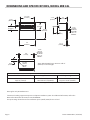
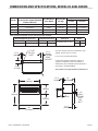
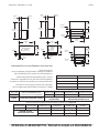
DIMENSIONS AND SPECIFICATIONS, MODEL MIR 34L
3-1/2"
[89mm]
18"
[457mm]
3-1/2"
[89mm]
9”
[229mm]
3/4"
[19mm]
4-1/2"
[114mm]
34"
[864mm]
15"
[381mm]
7"
[178mm]
1-3/4"
[44mm]
34-1/2"
[876mm]
30-11/16"
[779mm]
1-3/8"
[35mm]
REAR GAS
INLET ON
"W" & "C"
MODELS
3-1/4"
[83mm]
REAR GAS
INLET ON
"W" & "C"
MODELS
1/2" NPT
[13mm]
TOP GAS
INLET*
INSTALLATION NOTES
Combustible Wall Clearances ¹ Entry Clearances Manifold Operating Pressure
Sides: 6" (152mm)
Back: 6" (152mm)
Crated: 39 3/4" (997mm)
Uncrated: 34-3/4" (870mm)
Natural: 6" WC (15mbar)
Propane: 10" WC (25mbar)
¹NOTE: Installation clearance reductions are applicable only where local codes permit.
Data applies only to North America
Commercial cooking equipment requires an adequate ventilation system. For additional information, refer to the
National Fire Protection Association's standard NFPA96.
Gas input ratings shown here are for installations up to 2,000 ft. (610m) above sea level.
*Note: TOP GAS INLET pipe extension adds 4"
(258mm) to overall height.

Part # 1382669 Rev 1 (09/03/09) Page 5
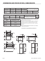
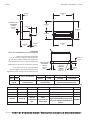
DIMENSIONS AND SPECIFICATIONS, MODEL IR-280L SERIES
1-3/4"
[44mm]
4-1/2"
[114mm]
1/2" N.P.T
TOP GAS
INLET
3-1/4"
[83mm]
OPTIONAL
REAR
GAS INLET
34"
[864mm]
30"
[762mm]
36"
[914mm]
15"
[381mm]
15"
[381mm]
1-3/4"
[45mm]
18"
[457mm]
1-3/8"
[35mm]
OPTIONAL
REAR
GAS
INLET
9"
[229mm]
3-1/2"
[89mm]
Gas input ratings shown for installations up to
2000 ft., (610m), above sea level.
For use on noncombustible oors
Commercial cooking equipment requires an
adequate ventilation system. For additional
information, refer to the National Fire Protection
Association's standard NFPA96.
This product is not approved for residential use.
Model
Width
(36" Broiler Plus Applicable Width
Flue Riser W/shelf)
Use With H280
Series Model
Shipping Wt.
Lbs./Kgs.
Entry Clearances: In (mm)
Crated Uncrated
IR36-280L 36" (914mm) H286 200/91 29" (737mm) 21" (533mm)
IR48-280L 48"(1219mm) H288 230/105 29" (737mm) 21" (533mm)
IR60-280L 60" (1524mm)) H284 & H287 260/118 29" (737mm) 21" (533mm)
IR72-280L 72" (1829mm) H289 280/127 29" (737mm) 21" (533mm)
Note Salamander Broiler on Left Side. Right Side Optional
Manifold Operating Pressure Installation Clearances Total Input Orice
Natural Propane Sides Rear
40,000 BTU/HR (11.7Kw)
NAT PRO
6"WC (15mbar) 10"WC (25mbar) 6"(152mm) 6"(152mm) #48F #55F

Part # 1382669 Rev 1 (09/03/09)Page 6
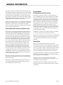
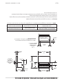
DIMENSIONS AND SPECIFICATIONS, CHEESE MELTER
Model Width Depth Height
Entry Clearances: All Models
GCM 24-280 24" (610,mm) 19" (483mm) 37-1/4" (946mm)
GCM 36-280 36" (314mm) 19" (483mm) 37-1/4" (946mm) Crated Uncrated
MCM 34 34" (864mm) 19" (483mm) 37-1/4" (946mm) 24"(610mm 20"(508mm)
Note: Data applies only to North America
Manifold Operating Pressure Installation Clearances Input: Natural and Propane Orice
Natural Propane Sides Rear
15,000 BTU/Hr (4.39 Kw) per Burner
30,000 BTU/Hr (8.79 Kw) Total
Nat #50F
6" WC (15 mbar) 10" WC (25 mbar) 6" (152mm) 6" (152mm)
Pro #57F
Model Shipping Wt. (Lbs./Kg)
GCM 34 180/82
GCM 36-280 180/82
GCM 60-280 220/100
GCM 72-280 240/109
20"
[508mm]
17-3/8"
[441mm]
31-1/4"
[794mm]
8-3/8”
[213mm]
5-13/32"
[137mm]
3-1/2"
[89mm]
15-1/2"
[394mm]
37-3/8"
[949mm]
37-3/8"
[949mm]
15-1/2"
[394mm]
3-1/2"
[89mm]
2-1/4"
[57mm]
19"
[483mm]
2"
[51mm]
34"
[864mm]
1/2" N.P.T. [13mm]
TOP GAS INLET
19"
483mm]
1/2" N.P.T.
[13mm]
TOP GAS
INLET
2-1/4"
[57mm]
2"
[51mm]
24"
[610mm]
17-3/8"
[441mm]
20"
[508mm]
5-13/32
[137mm]
8-3/8"
[213mm]
21-1/4"
[540mm]
NOTE: Installation clearance reductions are applicable
only where local codes permit
Commercial cooking equipment requires an adequate
ventilation system. For additional information, refer
to the National Fire Protection Association's standard
NFPA96.
Gas input ratings shown for installations up to 2000 ft.,
(610m), above sea level.
This product is not approved for residential use.

Part # 1382669 Rev 1 (09/03/09) Page 7
GENERAL INFORMATION
The range-mounted, gas Infra-Red Salamander Broiler and
Infra-Red Cheese Melter is designed as M Series and H/P280
Series Models for perfect match and t. The range-mounted,
gas Infra-Red Cheese Melter Broiler is designed as 40 Series
and H/P280 Series Models for perfect match and t. Ideal for
preparing melted cheese dishes, casseroles, au gratin dishes,
soués, Mexican food and other ethnic foods.
Garland/U.S. Range products are not approved or authorized
for home or residential use, but are intended for commercial
applications only. Garland / U.S. Range will not provide
service, warranty, maintenance or support of any kind other
than in commercial applications.
Salamander Performance and Construction
Two Hi-Low gas valves provide individual control of the (2)
atmospheric-type 20,000 BTU gas infra-red burners for the
Salamander. “LO” position is adjustable for most eld gas
pressure situations. Fast preheat and uniform production is
provided by the high-eciency, infra-red burners. Unique
atmospheric design eliminates the need for fans and lters.
Heat is directed downward to the large -380 square inch
plus – heavy duty broiling rack. Rack is easily removed from
spring balanced rack assembly. Rack assembly rolls out
for ease of loading and unloading. Rack assembly raises
and lowers with positive locking in three positions. Full-
width grease deector attached to the underside of the
rack assembly channels hot drippings to a large capacity
drain pan even when rack assembly is rolled out. The rack
assembly and drain pan are easily removed for cleaning.
The MIR34L is 34” wide and is supported by heavy-formed
brackets with stainless steel back-splash. Front and sides of
salamander are stainless steel.
IR36-280 is 36” wide, supported by heavy-formed brackets.
Salamander front & back-splash is stainless steel with black
baked enamel sides.
IR60-280L has a nished width of 60” which includes a 24”
wide shelf. Salamander front and back-splash is stainless
steel with black baked enamel sides.
Cheese Melter
Performance and Construction
Twenty-four inch wide model has a single atmospheric
type, 15,000 BTU gas infra-red burner. Thirty-four and thirty
six inch wide models each have two (2) atmospheric type,
15,000 BTU has infra-red burners. Burners are individually
controlled by three (3) position three (2) heat valves (HI, LO,
OFF). Fast preheat and uniform production is provided by
the high-eciency, infra-red burners. Unique atmospheric
design eliminates the need for fans and lters. Heat is
directed downward to the large heavy chrome-plated rack.
Sturdy chrome-plated rack guides support the rack, which
is adjustable to three (3) positions. Rack and rack guides are
easily removed for cleaning.
H/P280 Series and 40 Series range mounted cheese melters
are securely supported by heavy formed brackets.
H/P280 Series and 40 Series cheese melters are standard with
stainless steel fronts. Backsplash and remainder of exterior
are nished in black baked enamel. Pressure regulator is
standard.
Rating Plate
When corresponding with the factory or your local
authorized factory service center regarding service problems
or replacement parts, be sure to refer to the particular unit
by the correct model number (including the prex and sux
letters and numbers) and the warranty serial number. The
rating plate axed to the unit contains this information.
We suggest installation, maintenance and repairs should be
performed by your local authorized service agency listed in
your information manual pamphlet.
In the event you have any questions concerning the
installation, use, care or service of the product, write or call
our Product Service Department.
This product has been certied as commercial cooking
equipment and must be installed by professional personnel
as specied.

Part # 1382669 Rev 1 (09/03/09)Page 8
INSTALLATION
Statutory Regulations
The importance of the proper installation of Commercial
Gas Cooking Equipment cannot be over stressed. Proper
performance of the equipment is dependent, in great part,
on the compliance of the installation with the manufacturer’s
specications. Installation must conform to local codes or,
in the absence of local codes, with the National Fuel code,
ANSI Z223.1, Natural Gas Installation Code, CAN/GCA-B149.1
or the Propane Installation Code, CAN/CGA-B149.2, as
applicable.
Gas Connections
Before assembly and connection, check gas supply.
A. The type of gas for which the unit is equipped is stamped
on the data plate located on the lower front frame,
simply remove the drip pan for easy access. Connect a
unit stamped “NAT” only to natural gas; connect those
stamped “PRO” only to propane gas.
B. If it is a new installation, have gas authorities check meter
size and piping to assure that the unit is supplied with
sucient amount of gas pressure required to operate the
unit.
C. If it is additional equipment or replacement have a
qualied gas technician check the gas pressure to make
certain that existing gas facilities (meter piping, etc.) will
deliver the BTU’s of gas required at the unit with no more
than 1/2” water column pressure drop. When checking
pressure, be certain that other equipment on the same
gas line is on at full rate.
NOTE: When checking pressure, be sure that all other
equipment on the same gas line is on. A pressure regulator is
supplied with Garland Infra-Red Broilers. Regulator is preset
at deliver gas at pressure shown on the rating plate.
D. The appliance and its individual shut o (supplied by
others) must be disconnected from the gas supply piping
system during any pressure testing of that system at
pressures in excess of 1/2” psi (3.45 kPa).
E. The appliance must be isolated from the gas supply
piping system by closing its individual manual shut o
valve (supplied by others) during any pressure testing of
the gas supply piping system at test pressures equal to or
less than 1/2 psi (3.45 kPa).
F. Gas supply connection is made in back lower left hand
corner of unit. A readily accessible approved type of hand
valve should be installed on each supply line. Test for
leaks – DO NOT USE ANY OPEN FLAME.
G. A pressure tap plug is supplied with the units and it is
installed on the manifold. The drip pan must be removed
to use the pressure tap. The gas pressure must be
checked when the unit is installed, to insure that the unit
gas pressure is the same as specied on the rating plate.
If necessary, pressure adjustments must be made at the
pressure regulator, supplied on each Infra-Red Broiler.
NOTE: the pressure regulator is located at the top rear of the
salamander.
H. If it is completely new installation, have gas lines, meter
size piping and piping installed and checked by a
qualied gas technician.
I. Make certain that the new piping, joints and connections
have been made in a clean manner and have been
purged, so that the piping compound, chips, etc, will not
clog pilots, valves and/or controls. Use pipe joint sealant
that is resistant to liqueed petroleum gas.
WARNING Check gas connections for leaks. Use a soap
solution or similar means. DO NOT USE AN OPEN FLAME!
Note: This appliance is not recommended for residential
installation.
Pressure Regulators in Battery Installations
1. Must have a maximum regulation capacity for the total
connected load.
2. The pressure regulator(s) installed must be listed by a
nationally recognized agency.
3. The pressure regulator(s) must have a pressure
adjustment range to allow adjustment to the manifold
pressure on the appliance rating plate.
4. Unless the manifold pressure on all connected appliances
is the same, a separate regulator must be supplied for
each appliance(s) having dierent manifold pressures.
5. Gas supply lines may be connected at right, left or
both ends of a battery or at the tee connections on
spreader plates. If ve (5) or more units are placed in a
battery, more that one (1) supply line should be used. A
readily accessible, approved type of hand shut o valve
(supplied by others) should be installed on each supply
line.

Part # 1382669 Rev 1 (09/03/09) Page 9
INSTALLATION Continued
CAUTION: Local codes may require that the pressure
regulator be externally vented. This is to be supplied by
others.
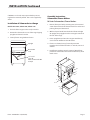
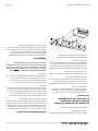
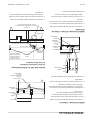
Installation of Salamander to a Range
Models IR36-280L, GCM24-280, GCM26-280
1. The back of the range must be easily accessible
2. Position the salamander on rear of the range slipping
uprights into burner box sides.
3. Securely fasten using hardware shown.
Upright
Burner Box
Side
1/4" x 3/4"
Type "B"
Washer Hex Head SMS
4 Req'd
Assembly Instructions
Salamander/Cheese Melters
M-Series Salamanders/Cheese Melters
1. Remove front panel #5 by removing two (2) sheet metal
screws from under side of salamander/cheese melter and
pushing front panel downward.
2. With back panel #4 still attached to the left #2 and right
#3 uprights drop uprights into the rectangular cutouts at
the rear of the range.
3. Fasten uprights #2 and #3 to the range #1 with four (4)
5/16” -18 bolts and at washers #6 and #7.
4. If unit is in a battery line up, fasten adjacent units
together at hole marked “X” with 1/4” -20 bolts, nuts and
washers.
5. Install front panel #5 previously removed. Attach front
panel #5 to salamander/cheese melter with two (2) sheet
metal screws
~
1
"X"
"X"
2
8
4
3
6
7
5
GARLAND

Part # 1382669 Rev 1 (09/03/09)Page 10
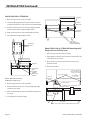
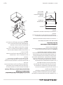
INSTALLATION Continued
Models IR-L, GCM-
1. Back of range must be easily accessible.
2. Fasten mounting bracket to burner box back as shown
using four (4) of #10 x ½” type “A” truss head SMS, Phillips.
3. Position salamander on rear of range slipping uprights
into burner box sides and mounting bracket.
4. Make sure front panel is in front of stabilizer bracket.
5. Securely fasten using hardware shown.
Upright
Burner Box
Back
Stabilizer
Bracket
Mounting
Bracket
Mounting
Bracket
Top
Bottom
Models IR48-280L IR72-280L,
GCM48-280, GCM72-280
1. Back of range must be easily accessible.
2. Position salamander on rear of range slipping uprights
into burner box sides.
3. Make sure front panel is in front of stabilizer bracket on
72” range.
4. Securely fasten hardware shown.
Upright
Burner
Box Side
Stabilizer
Bracket
1/4" x 3/4"
Type "B" Washer
Hex Head (8 Req'd)
Models IR-L or GCM- Mounting to ”
Range with one Full Size Oven
1. Back of range must be easily accessible.
2. If mounting to a double oven, remove oven ue from left
side looking at rear of unit.
3. Place salamander in place and fasten securely, using
hardware shown.
4. Re-install oven ue.
# 10 x 3/4"
Phillips Truss
Head
1/4" 20 x 3/4" Hex
Head Self Tapping
Screws (2 ea. Side)
&
1/4 x 2/4 Washer
(2 ea. Side)
End Support Bracket
Center Support
Use Existing # 10 Sheet Metal Screws
From Back Flange
Back Flange
Rear View
Remove Oven Flue for H/P288 Double Ovens Only

Part # 1382669 Rev 1 (09/03/09) Page 11
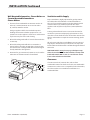
Wall Mounted Salamanders, Cheese Melters or
Counter Mounted Salamander or
Cheese Melters
1. Clearance from combustible construction must be six
inches (6”, 152mm) minimum at rear and six inches
(6”, 152mm) minimum at sides.
Each gas appliance shall be located with respect to
building construction and other equipment so as to
permit access to the appliance. Such access and clearance
my be necessary for service and cleaning.
2. All models ending with sux “C” must be fastened to the
counter top.
3. All models ending with sux “W” are mounted to a
vertical surface using the mounting kit as shown below.
The salamanders are shipped with the wall mounting kit
already attached to the appliance.
4. Provisions for gas connections, bottom or rear, should be
taken into consideration at time of installation.
INSTALLATION Continued
Ventilation and Air Supply
Proper ventilation is highly important for good operation.
The ideal method of ventilation a Salamander Broiler is
the use of a properly designed canopy hood which should
extend six inches (6”, 152mm) beyond all sides of the
appliance and six (6) feet six (6) inches (1981mm)from the
oor.
A strong exhaust fan will create a vacuum in the room, for
an exhaust system to work properly, replacement air must
enter the room in which the vent is located. the amount of air
which is exhausted must equal the amount entering, (make-
up air).
All gas burners and pilots need sucient air to operate and
large objects should not be placed in front or on top of the
broiler which would obstruct the air ow through the front of
the broiler.
FOR YOUR SAFETY never place any type of object on top
of the salamander broiler or cheese melters. The top of the
broiler will exceed 1000° F (538° C). It could cause severe
burns or re and obstruct ventilation.
Clearances:
Clearance must be 6” (152mm) sides and rear from
combustible material. A clearance of 0.0” to non combustible
construction as sides & rear is acceptable, for the Salamander,
The Cheese melter is not suitable for installation on a
combustible oor.

Part # 1382669 Rev 1 (09/03/09)Page 12
OPERATION
Pilot Lighting Instructions
1. The in-line service shut-o valve should be in the “ON”
position.
2. With a lighted taper you can now light in the pilots which
are located at the rear of the main burner.
3. Pilot ame should be approximately 7/8” long for proper
ignition of the burners. The pilot adjustment valve can
be located by sliding the drip tray forward. Adjustment
valves are located on the manifold pipe which runs
horizontal across the back of the unit, behind the drip
tray, one is at the left rear and the other at the right rear.
To adjust the pilot light, turn the brass screw counter-
clock-wise to increase the pilot ame, and clock-wise to
decrease the pilot ame.
NOTE: No more than 7/8” pilot ame length should be
required. Too high a setting will cause the fame to lift o
or will create excessive carboning. Do not adjust the pilot
ame lower than 7/8” long because this can cause delayed
ignition at the burner. The delayed ignition could cause the
burner tiles to crack; in that case the burner would have to be
replaced.
Main Burner Operation
Turn main burner knob to the “MAX” position immediately
check ignition.
CAUTION Should ignition fail after ve seconds, turn valve
o and wait ve minutes before trying again. Pilot gas is
not interrupted automatically. It is the responsibility of the
operator to check the ignition of burners immediately after
the burner valve has been turned on.
When ignition has been accomplished, a blue ame will
cover the surface of the ceramics for 10-15 seconds. The haze
will disappear and the burner rod will glow red. After the
burners have operated for several minutes turn the valve to
“MIN.” The burner rods will no longer glow red and the ame
travels back and forth on the face of the burner ceramics.
Burn o Period
Many parts used in the manufacturing of commercial
equipment have a thin, protective coating of machine oil.
This oil should be burned o before the equipment is used
for food preparation.
After all start-up and safety checks have been completed,
turn burner valve to the “MAX” position. Smoke (a bluish
haze) will be produced. This process can take several hours
and can be completed over a few days.
Energy Conservation
Do not waste energy by leaving controls at high temperature
settings during idle periods. Lower settings will keep broiler
warm and ready for next use period. Reset burner valve knob
as required for heavy load periods.
Shut Down Instructions
Turn main burner valve knobs to the “OFF” position. If the
unit is to be shut down for an extended period of time, close
the manual in-line service valve o, (manual in-line service
valve is not factory supplied).
FOR YOUR SAFETY never place any type of object on top
of the salamander broiler or cheese melters. The top of the
broiler will exceed 1000° F. It could cause severe burns and/
or re and also will obstruct ventilation.
Main Burner Adjustments
All Salamanders are provided with a xed burner orices to
provide 20,000 BTU/HR at the “MAX” setting on propane gas
supplied at 10.0” W/C. All Cheese Melters are provided with a
xed burner orices to provide 15,000 BTU/HR at the “MAX”
setting on natural gas supplied at a 6.0” W/C pressure and
15,000 BTU/HR at the “MAX” setting on propane gas supplied
at 10.0” W/C.
The “MIN” setting is adjustable and should be set as follows:
1. Set the burner valve knob to “MIN” setting and remove
the knob.
2. Insert a thin bladed screwdriver into the valve stem
to engage the slot inside the stem. Turn clockwise to
decrease the rate and counter-clockwise to increase.
Proper adjustment is attained at the point where the burner
rods no longer glow and the ame travels back and forth on
the face of the ceramics.
This adjustment has been factory pre-set, however, with
changing pressures this adjustment and pilot adjustment
may need to be re-done after installation.
This is not considered a manufacturing defect and is not
warrantable.

Part # 1382669 Rev 1 (09/03/09) Page 13
MAINTENANCE AND CLEANING
A program of proper cleaning techniques will aid in
continued trouble free operation of this or any quality
equipment.
Daily
Grid racks should be wiped daily while still warm, using a
heavy cloth or other grease absorbing material to remove
grease and burnt food before they burn into the grid.
Remove burnt materials, such as carbonized grease or
food, with a sti wire brush. DO NOT USE ANY TYPE OF
STEEL WOOL. Small particles may be left on the grid surface
and get into food products. Grid racks should be washed
thoroughly using a wire brush and a hot, mild detergent or
soap solution. Rinse with clear, warm water.
Monthly
Lubricate valves and bearings as required. Due to the
usual location of the broiler that is mounted above a range
with open tops, the heat from the open top will cause the
lubrication grease inside the valves to dry out. When you
notice that the valve is becoming harder to turn it is then
time to have them greased. We suggest an Authorized
Service Agent who is familiar with the appliance and working
with natural and propane gas, to perform this type of work.
Exterior Cleaning
Establish a regular schedule. Any spills should be wiped o
immediately.
1. Wipe exposed, clean-able surface when cool with a mild
detergent and hot water. Stubborn residue spots may be
removed with a light weight non-metallic scouring pad.
Dry thoroughly with a clean cloth.
2. Stainless steel should be cleaned using a mild detergent,
a soft cloth and hot water. If it is necessary to use a non-
metallic scouring pad, always rub in the direction of the
grain in the metal to prevent scratching. Use a water
based stainless steel cleaner (such as Drackett Twinkle), if
you want a high shine.


Pièce nº 1382669 Rev 1 (09/03/09) Page 13
1. Placer le bouton du robinet de brûleur au réglage
« MIN » et retirer le bouton.
2. Insérer un petit tournevis plat dans la tige du robinet
a n qu’il s’engage dans la fente à l’intérieur de la tige.
Tourner à droite pour diminuer le débit et à gauche pour
l’augmenter.
Un réglage correct est atteint lorsque les tiges du brûleur
ne rougeoient plus et que la amme se déplace d’avant en
arrière sur les briques.
Ce réglage est e ectué en usine; cependant, avec les
modi cations de pression, il peut être nécessaire d’e ectuer
ce réglage ainsi que celui de la veilleuse une fois l’installation
e ectuée.
Cela n’est pas considéré comme un défaut de fabrication et
n’est pas couvert par la garantie.
FONCTIONNEMENT suite
ENTRETIEN ET NETTOYAGE
Un programme de techniques de nettoyage adaptées
permettra d’obtenir un fonctionnement continu sans
problème de cet équipement ou de tout équipement de
qualité.
Chaque Jour
Les grilles devront être essuyées chaque jour pendant
qu’elles sont encore tièdes, en utilisant un chi on épais ou
tout autre matériel absorbant la graisse pour éliminer la
graisse et les aliments brûlés avant qu’ils ne s’incrustent dans
la grille. Éliminer les aliments brûlés, tels que la graisse ou
les aliments carbonisés, avec une brosse métallique dure.
NE PAS UTILISER DE LAINE D’ACIER. Des petites particules
peuvent rester sur la surface de la grille et coller aux aliments.
Les grilles devront être lavées soigneusement avec une
brosse métallique et une solution chaude de détergent doux
ou de savon. Rincer à l’eau tiède propre.
Chaque Mois
Lubri er les robinets et roulements si nécessaire. En raison
de l’emplacement habituel de la salamandre qui est montée
au-dessus d’une cuisinière avec grilloirs à plaque ouverte,
la chaleur du grilloir fera sécher la graisse de lubri cation
à l’intérieur des robinets. Lorsque l’on remarque que le
robinet devient di cile à tourner, il est temps de le graisser.
Nous suggérons de faire e ectuer ce travail par un agent
d’entretien autorisé connaissant bien l’appareil et les
équipements fonctionnant au gaz naturel et au propane.
Nettoyage Extérieur
Établir un calendrier régulier. Tout déversement devra être
essuyé immédiatement.
1. Essuyer les surfaces nettoyables exposées une fois
refroidies avec un détergent doux et de l’eau chaude. Les
résidus rebelles peuvent être éliminés avec un tampon à
récurer léger non métallique. Bien sécher avec un chi on
propre.
2. L’acier inoxydable devra être nettoyé avec un détergent
doux, un chi on et de l’eau chaude. S’il est nécessaire
d’utiliser un tampon à récurer non métallique, frotter
dans le sens du grain du métal pour éviter de le rayer.
Utiliser un produit de nettoyage pour acier inoxydable à
base d’eau (tel que Drackett Twinkle) si l’on veut obtenir
un ni brillant.

Pièce nº 1382669 Rev 1 (09/03/09)Page 12
FONCTIONNEMENT
Instructions D’allumage Des Veilleuses
1. Le robinet d’arrêt en ligne devra être en position ouverte.
2. Avec une mèche allumée, il est maintenant possible
d’allumer les veilleuses qui sont situées à l’arrière du
brûleur principal.
3. La amme des veilleuses devrait avoir une longueur
approximative de 7/8 po (22mm) pour allumer
correctement les brûleurs. On peut accéder aux robinets
de réglage des veilleuses en faisant glisser vers l’avant le
bac récepteur. Les robinets de réglage sont situés sur le
collecteur placé horizontalement en travers de l’arrière de
l’appareil, derrière le bac récepteur, un à gauche et l’autre
à droite.
Pour régler les veilleuses, tourner la vis en laiton vers la
gauche pour augmenter la amme et vers la droite pour
la diminuer.
NOTA : Une amme de veilleuse d’une hauteur de
7/8 po (22mm) devrait être su sante. Un réglage trop haut
fera décoller la amme ou créera une formation excessive
de carbone. Ne pas régler la amme des veilleuses à une
longueur inférieure à 7/8 po (22mm) car cela retardera
l’allumage des brûleurs. Ce retard d’allumage pourrait causer
une ssuration des briques des brûleurs. Dans ce cas, le
brûleur devra être remplacé.
Fonctionnement Du Brûleur Principal
Ouvrir le robinet du brûleur principal en position
« MAX ». Véri er immédiatement l’allumage du brûleur.
Attention : Si l’allumage ne se fait pas dans un délai de cinq
secondes, fermer le robinet et attendre cinq minutes avant
de recommencer. Le gaz de la veilleuse n’est pas coupé
automatiquement. Il est de la responsabilité de l’opérateur
de véri er l’allumage des brûleurs immédiatement après
que le robinet des brûleurs ait été mis en position de
marche.
Une fois l’allumage fait, une amme bleue couvrira la surface
des briques pendant 10 à 15 secondes. La vapeur disparaîtra
et la tige du brûleur deviendra rouge. Une fois que les
brûleurs ont fonctionné pendant plusieurs minutes, tourner
le robinet sur la position « MIN ». Les tiges des brûleurs ne
seront plus rouges et la amme parcourra d’avant en arrière
la face des briques du brûleur.
Période De Calcination
Beaucoup de pièces utilisées dans la fabrication de
l’équipement commercial sont revêtues d’une ne couche
protectrice d’huile pour machines. Cette huile devra
être calcinée avant que l’équipement soit utilisé pour la
préparation d’aliments.
Après tout démarrage, et une fois les véri cations de sécurité
terminées, tourner le robinet des brûleurs à la position «
MAX ». Il se produira de la fumée (un nuage bleuâtre). Ce
processus peut prendre plusieurs heures et peut être exécuté
sur plusieurs jours.
Pour Conserver L’énergie
Ne pas gaspiller l’énergie en laissant les commandes sur
des réglages de température élevée pendant les périodes
d’inactivité. Des réglages plus bas maintiendront la
salamandre chaude et prête pour la période d’utilisation
suivante. Régler à nouveau les boutons des robinets des
brûleurs si nécessaire pour les périodes de forte charge.
Instructions D’arrêt
Tourner les boutons des robinets des brûleurs en position «
OFF ». Si l’appareil doit être arrêté pendant une période de
temps prolongée, fermer le robinet d’arrêt manuel en ligne
(ce robinet n’est pas fourni par l’usine).
POUR DES QUESTIONS DE SÉCURITÉ, ne jamais placer
d’objets sur le dessus des salamandres ou des salamandres
à fromage. La température sur le dessus de la salamandre
dépasse 1 000 °F (538°C). Cela pourrait causer des brûlures
graves ou un incendie et obstruer la ventilation.
Réglages Des Brûleurs Principaux
Toutes les salamandres sont livrées avec des ori ces de
brûleur xes fournissant 20 000 BTU/H au réglage
« MAX » avec du gaz naturel à une pression de 6 po C/E et
20 000 BTU/H au réglage « MAX » avec du propane à une
pression de 10 po C/E. Toutes les salamandres à fromage
sont livrées avec des ori ces de brûleur xes fournissant 15
000 BTU/H au réglage « MAX » avec du gaz naturel à une
pression de 6 po C/E et 15 000 BTU/H au réglage « MAX »
avec du propane à une pression de 10 po C/E.
Le réglage « MIN » peut être modi é et devra être réglé
comme suit :

Pièce nº 1382669 Rev 1 (09/03/09) Page 11
INSTALLATION suite
Ventilation Et Alimentation En Air
Une ventilation correcte est extrêmement importante pour
un bon fonctionnement. La méthode idéale de ventilation
d’une salamandre consiste à utiliser une hotte correctement
conçue qui devrait se prolonger de six pouces (6 po, 152mm)
au-delà de tous les côtés de l’appareil et être à six pieds (6 pi)
six pouces (6 po) (1981mm) du plancher.
Un ventilateur d’extraction puissant créera un vide dans
la pièce. Pour que le système d’évacuation fonctionne
correctement, de l’air de remplacement doit entrer dans la
pièce dans laquelle est située l’évacuation. La quantité d’air
évacué doit être égale à la quantité entrant dans la pièce (air
d’appoint).
Tous les brûleurs à gaz et veilleuses ont besoin de
su samment d’air pour fonctionner et on ne devra pas
placer de grands objets devant ou sur le dessus de la
salamandre qui empêcheraient l’air de circuler à l’avant de la
salamandre.
POUR DES QUESTIONS DE SÉCURITÉ, ne jamais placer
d’objets sur le dessus des salamandres ou des salamandres
à fromage. La température sur le dessus de la salamandre
dépasse 1 000 °F (538°C). Cela pourrait causer des brûlures
graves ou un incendie et obstruer la ventilation.
Dégagements :
Le dégagement par rapport aux matériaux combustibles
doit être de 6 po (152 mm) sur les côtés et à l’arrière. Un
dégagement de 0 po par rapport aux matériaux non
combustibles est acceptable sur les côtés et à l’arrière pour la
salamandre. La salamandre à fromage n’est pas conçue pour
être installée sur un plancher combustible.
3. Mettre en place la salamandre et bien la xer en utilisant
la quincaillerie illustrée.
4. Remonter le conduit de fumée du four.
Salamandres Et Salamandres À Fromage
Montées Sur Mur Ou Salamandre
Ou Salamandre À Fromage Montées
Sur Comptoir
1. Le dégagement par rapport à toute construction
combustible doit être de six pouces (6 po, 152mm) au
minimum à l’arrière et de six pouces (6 po, 152mm) au
minimum sur les côtés.
Chaque appareil à gaz sera placé par rapport au bâtiment
et aux autres équipements de façon à avoir accès à
l’appareil. Cet accès et ces dégagements sont nécessaires
pour l’entretien et le nettoyage.
2. Tous les modèles dont le numéro se termine par le su xe
« C » doivent être xés au comptoir.
3. Tous les modèles dont le numéro se termine par le su xe
« W » sont montés sur une surface verticale en utilisant
l’ensemble de montage comme illustré ci-dessous. Les
salamandres sont expédiées avec l’ensemble de montage
mural xé à l’appareil.
4. Au moment de l’installation, on devra prévoir les
connexions du gaz, en dessous ou à l’arrière.

Pièce nº 1382669 Rev 1 (09/03/09)Page 10
INSTALLATION suite
MODÈLES IR-L, GCM-
1. L’arrière de la cuisinière doit être facilement accessible.
2. Fixer le support de montage à l’arrière du boîtier des
brûleurs comme illustré en utilisant quatre (4) vis à
métaux à tête bombée Phillips de type « A »
n° 10 x 1/2 po.
3. Positionner la salamandre à l’arrière de la cuisinière en
faisant glisser les montants dans les côtés du boîtier des
brûleurs et dans le support de montage.
4. S’assurer que le panneau avant est en face du support
stabilisateur.
5. Bien xer en utilisant les pièces de xation illustrées.
Montant
Arriere
Du Boîtier
Des
Brûleurs
Support
Stabilsatur
Support
De Montage
Support
De Montage
Haut
Bas
MODÈLES IR-L, IR-L, GCM-,
GCM-
1. L’arrière de la cuisinière doit être facilement accessible.
2. Positionner la salamandre à l’arrière de la cuisinière en
faisant glisser les montants dans les côtés du boîtier des
brûleurs.
3. S’assurer que le panneau avant se trouve en face du
support stabilisateur sur la cuisinière de 72 po.
4. Bien xer la quincaillerie illustrée.
Montant
Côté Du
Boîtier
Des Brûleurs
Support
Stabilisateur
1 /4 Po X 3/4 Po
Vis À Tête
Hexagonale Rondelle
Type « B »
(8 Nécessaires)
Modèles IR-L Ou GCM- Montage
Sur Une Cuisinière De Po Avec
Un Four Pleine Grandeur
Vis Philips À
Tête Bombée
N° 10 X 3/4 Po
Vis Autotaraudeuse
1/4 Po 20 X 3/4 Hex.
(2 De Chaque Côté)
Et Rondelle 1/4 X 3/4
(2 De Chaque Côté)
Support
D'extrémité
Support Central
Utiliser Les Vis Parker N° 10 Existantes
De La Bride Arrière
Back Flange
Vue Arrière
Retirer Le Conduit De Fumée Du Four Pour
Les Fours Doubles H/P288 Seulement.
1. L’arrière de la cuisinière doit être facilement accessible.
2. En cas de montage sur un four double, retirer le conduit
de fumée du four du côté gauche en regardant l’arrière
de l’appareil.

Pièce nº 1382669 Rev 1 (09/03/09) Page 9
INSTALLATION suite
3. Les régulateurs de pression doivent avoir une gamme de
réglages de pression permettant un réglage conforme
à la pression de collecteur indiquée sur la plaque
signalétique de l’appareil.
4. A moins que la pression de collecteur sur tous les
appareils branchés soit identique, un régulateur de
pression séparé doit être installé sur chaque appareil
ayant des pressions de collecteur di érentes.
5. Des conduites d’alimentation en gaz doivent être
branchées aux extrémités droite, gauche ou aux deux
extrémités d’une batterie ou aux connexions en TÉ sur
des plaques de répartition. Si cinq (5) unités ou plus sont
placées dans une batterie, on devra utiliser plus d’une
(1) conduite d’alimentation. Un robinet d’arrêt manuel
de type homologué et facilement accessible devra être
installé sur chaque conduite d’alimentation.
ATTENTION : Les codes locaux peuvent exiger que le
régulateur de pression soit ventilé à l’extérieur. Celui-ci n’est
pas fourni par nous-mêmes.
Installation De La Salamandre
Sur Une Cuisinière
Modèles IR36-280L. GCM24-280. GCM26-280
1. L’arrière de la cuisinière doit être facilement accessible
2. Placer la salamandre à l’arrière de la cuisinière en
faisant glisser les montants dans les côtés du boîtier des
brûleurs.
3. Immobiliser la salamandre en utilisant la quincaillerie
illustrée.
Montant
Côté Du Boîtier
Des Brûleurs
1/4 x 3/4 po
Type «B»
Vis À Métaux Tête Hex.
Avec Rondelle
4 Nécessaires
Instructions De Montage Des Salamandres/
Salamandres À Fromage
Salamandres/Salamandres À Fromage Série M
1. Retirer le panneau avant n° 5 en retirant les deux (2)
vis Parquer de la partie inférieure de la salamandre/
salamandre à fromage et en poussant le panneau avant
vers le bas.
2. Avec le panneau arrière n° 4 toujours xé aux montants
gauche n° 2 et droit n° 3, faire descendre les montants
dans les découpes rectangulaires à l’arrière de la
cuisinière.
3. Fixer les montants n° 2 et n° 3 à la cuisinière
n° 1 avec quatre (4) boulons 5/16 po et 18 rondelles
plates n° 6 et n° 7.
4. Si l’appareil est aligné en batterie, xer les unités
adjacentes ensemble au trou marqué « X » avec des
boulons 1/4 po-20 des rondelles et des écrous.
5. Remonter le panneau avant n° 5 démonté
précédemment. Fixer le panneau avant n° 5 à la
salamandre/salamandre à fromage avec deux (2) vis
Parquer.
~
1
"X"
"X"
2
8
4
3
6
7
5
G
AR
L
A
ND
La page est en cours de chargement...
La page est en cours de chargement...
La page est en cours de chargement...
La page est en cours de chargement...
La page est en cours de chargement...
La page est en cours de chargement...
La page est en cours de chargement...
La page est en cours de chargement...
-
 1
1
-
 2
2
-
 3
3
-
 4
4
-
 5
5
-
 6
6
-
 7
7
-
 8
8
-
 9
9
-
 10
10
-
 11
11
-
 12
12
-
 13
13
-
 14
14
-
 15
15
-
 16
16
-
 17
17
-
 18
18
-
 19
19
-
 20
20
-
 21
21
-
 22
22
-
 23
23
-
 24
24
-
 25
25
-
 26
26
-
 27
27
-
 28
28


Garland E20 Series Owner Instruction Manual
- Taper
- Owner Instruction Manual
dans d''autres langues
- English: Garland E20 Series
Documents connexes
-
Garland E20 Series Owner Instruction Manual
-
-
-
Garland Broiler Manuel utilisateur
-
-
Garland 36ER36 Mode d'emploi
-
Garland 36ER36 Owner Instruction Manual
-
Garland SRC Manuel utilisateur
-
-
Autres documents
-
Vulcan 36RB Manuel utilisateur
-
Vulcan-Hart VB73 Manuel utilisateur
-
Vulcan-Hart GHIR44-ML-52210 spécification
-
Vulcan 36C-6B Le manuel du propriétaire
-
ROLLER GRILL SEM 800 PDS Instructions for Use and Installation
-
Buffalo CD679 Le manuel du propriétaire
-
-
Modular 318009 Manuel utilisateur
-
Vulcan 36ESB C36ESB Salamander Broiler Le manuel du propriétaire
-