Graco 231-043 Instructions and Parts List
- Catégorie
- Pulvérisateur de peinture
- Taper
- Instructions and Parts List

INSTRUCTIONS–P
ARTS LIST
307–785
Rev J
Supersedes
H
120 VAC, 15 AMP
Ultra 1000
Airless Paint Sprayer
3000 psi (210 bar) Maximum Working Pressure
Model 231–034, Series D
This
is a basic sprayer on an upright cart
and does not include a hose or a gun.
Model 231–043, Series B
This
is a complete sprayer on an upright cart and
includes a hose, a gun, a RAC IV
DripLess
Tip
Guard, and a SwitchT
ip.
U.S.
P
A
TENT NO. 4,323,741; 4,397,610
PATENTED 1983, CANADA
AND OTHER PATENTS PENDING
GRACO INC. P.O. BOX 1441
MINNEAPOLIS, MN
55440–1441
COPYRIGHT
1986, GRACO INC.
This manual contains important
warnings and information.
READ AND RETAIN FOR REFERENCE
MODEL 231–043

Table
of Contents
Introduction 2.
. . . . . . . . . . . . . . . . . . . . . . . . . . . . . . . . . . .
Warnings 4
. . . . . . . . . . . . . . . . . . . . . . . . . . . . . . . . . . . . . .
Setup 10
. . . . . . . . . . . . . . . . . . . . . . . . . . . . . . . . . . . . . . . .
Operation 12
. . . . . . . . . . . . . . . . . . . . . . . . . . . . . . . . . . . .
Shutdown
And Care
14.
. . . . . . . . . . . . . . . . . . . . . . . . . .
Flushing
Guidelines
15.
. . . . . . . . . . . . . . . . . . . . . . . . . .
Troubleshooting
Guide
16.
. . . . . . . . . . . . . . . . . . . . . . . .
Spin Test 22.
. . . . . . . . . . . . . . . . . . . . . . . . . . . . . . . .
Bridge Test 23.
. . . . . . . . . . . . . . . . . . . . . . . . . . . . . .
Repair
General
Repair Information
24.
. . . . . . . . . . . . . . . .
Motor
Brush
25.
. . . . . . . . . . . . . . . . . . . . . . . . . . . . .
Power
Supply Cord
26.
. . . . . . . . . . . . . . . . . . . . . . .
On/Off
Switch
26.
. . . . . . . . . . . . . . . . . . . . . . . . . . . .
Bridge
Rectifier
27.
. . . . . . . . . . . . . . . . . . . . . . . . . .
Circuit
Breaker
27.
. . . . . . . . . . . . . . . . . . . . . . . . . . .
Circuit
Board
28.
. . . . . . . . . . . . . . . . . . . . . . . . . . . .
Pressure
Control
29.
. . . . . . . . . . . . . . . . . . . . . . . . .
Pressure
Control Adjustment
30.
. . . . . . . . . . . . . . .
Bearing
Housing & Connecting Rod
32.
. . . . . . . . .
Drive
Housing
33.
. . . . . . . . . . . . . . . . . . . . . . . . . . .
Motor 34
. . . . . . . . . . . . . . . . . . . . . . . . . . . . . . . . . . . .
Removing
and Installing a Pump
36.
. . . . . . . . . . . .
Displacement
Pump
37.
. . . . . . . . . . . . . . . . . . . . . .
Parts
Sprayer
40.
. . . . . . . . . . . . . . . . . . . . . . . . . . . . . . . . .
Pressure
Control
42.
. . . . . . . . . . . . . . . . . . . . . . . . .
Wiring
Diagram
43.
. . . . . . . . . . . . . . . . . . . . . . . . . . .
Displacement
Pump
44.
. . . . . . . . . . . . . . . . . . . . . .
Technical
Data
47.
. . . . . . . . . . . . . . . . . . . . . . . . . . . . . . .
Dimensions 47
. . . . . . . . . . . . . . . . . . . . . . . . . . . . . . . . . . .
Graco
Phone Numbers
47.
. . . . . . . . . . . . . . . . . . . . . . . .
The
Graco W
arranty and Disclaimers
48.
. . . . . . . . . . .
Liquids can be injected into the body by high pressure airless
spray
or leaks – especially hose leaks.
Keep
body clear of the nozzle. Never stop leaks with any part of the
body.
Drain
all pressure before removing parts. A
void accidental
triggering
of gun by always setting safety latch
when not spraying.
Never
spray without a tip guard.
In case of accidental skin injection, seek immediate “Surgical
Treatment”.
Failure
to follow this warning can result in amputation or serious
injury.
FIRE
AND
EXPLOSION HAZARD
SKIN INJECTION
HAZARD
READ AND UNDERSTAND ALL LABELS AND INSTRUCTION MANUALS BEFORE USE
Spray
painting, flushing or cleaning equipment with flammable liq
-
uids
in confined areas can result in fire or explosion.
Use
outdoors or
in extremely well ventilated areas. Ground equip
-
ment,
hoses, containers and objects being sprayed.
Avoid all ignition sources such as static electricity from plastic
drop
cloths, open flames such as pilot lights, hot objects such as
cigarettes,
arcs from connecting or disconnecting
power cords or
turning
light switches on and off.
Failure
to follow this warning can result in death or serious injury
.
NOTE: This
is an example of the DANGER
label on your sprayer. If you have operators
who do not read the English language, order
one of the labels shown to the right. Place the
label on the sprayer in the location shown at A.
The labels are available directly from Graco,
free of charge. Call 1–800–328–021
1.
French 185–955
Spanish 185–962
German 186–042
Greek 186–046
Korean 186–050
A
01217A

Introduction
Pressure Control
The
pressure control includes an ON/OFF switch for
the sprayer
, the pressure–adjusting control knob, a
pressure–sensing device and a current–overload cir
-
cuit breaker with a manual–reset button. The pressure
control regulates the motor speed.
Motor
The DC motor has sealed bearings and replaceable
motor brushes. The motor operates whenever there is
a demand for fluid or additional fluid pressure. When
the pump is cycling, the motor sounds like the cranking
of an automobile starter
. When the pump is not cy
-
cling, the motor hums intermittently until the fluid pres
-
sure stabilizes, then the motor will shuts of
f. However
,
there is still power to the sprayer and the sprayer stays
pressurized and ready to use until you manually shut it
of
f and relieve the pressure.
The direct–current (DC) motor is less sensitive to low
voltage or voltage fluctuations than an alternating–cur
-
rent (AC) motor
. However
, long extension cords may
af
fect the sprayer performance.
Drive Assembly
The
drive assembly, which is sealed, transfers power
from the DC motor to the displacement pump.
Displacement Pump
The
displacement pump provides equal fluid delivery
on both the up and the down pump stroke strokes. The
pump has a packing nut which, when filled with Graco
Throat Seal Liquid T(SL), helps prevent damage to the
throat packings and piston rod.
Fluid Filter
The
fluid filter strains the paint to help avoid clogs in
the hose and the spray tip. The filter includes a reus
-
able element and has a pressure drain valve for manu
-
ally relieving fluid pressure.
Hoses
The grounded, nylon spray hoses have spring guards
on both ends. The 50 foot (15.2 meter) hose has a 1/4
inch ID. The 3 foot (0.9 meter), 3/16 inch ID hose pro
-
vides more flexible gun movement. The nylon hose
material acts as a pulsation dampener to absorb pres
-
sure fluctuations.
Spray Gun & RAC IV DripLess Tip Guard
The
spray gun has a trigger safety which prevents ac
-
cidental triggering when it is locked. The gun has a
filter for final paint–straining. The Reverse-A-Clean IV
(RAC IV) SwitchT
ip uses high pressure fluid to remove
clogs from the spray tip without removing it from the
gun. The RAC IV DripLess tip guard is a safety feature
which helps reduce the risk of a skin injection injury
.
4066b
74
C
B
A
66
61
6773
75
76
ED102 101
100
KEY
40 Nipple,
for second hose
61
Pail hanger
66
Fluid Filter
66b
Nipple, for the main fluid hose
67
Drive Assembly
73 Motor
74
Pressure drain valve
75
Pressure control
76
Displacement pump
100
Main fluid hose
101
Whip hose
102
Contractor gun
A
Reset button
B
On/OFF switch
C
Pressure Adjusting Knob
D SwitchTip
E
RAC IV tip guard
FT
rigger safety shown locked
Fig.
1

4307-785
WARNINGS
High Pressure Spray Can Cause Serious Injury
. For Professional Use Only.
Observe All W
arnings. Read and understand all instruction manuals before operating equipment.
FLUID
INJECTION HAZARD
General
Safety
This
equipment generates very high fluid pressure. Spray from
the
gun, leaks or ruptured components can inject fluid through
your
skin and into your body
and cause extremely serious bod
-
ily
injury
, including the need
for amputation. Also, fluid injected
or
splashed into the eyes or
on the skin can cause serious dam
-
age.
Never
point the spray gun at anyone or at any part of the body
.
Never put hand or fingers over the spray tip. Never try to “blow
back”
paint; this is Not an air spray system.
Always
have the tip guard in place on the spray gun when spray
-
ing.
Always follow the Pressure Relief Procedure, below, before
cleaning or removing the spray tip or servicing any system
equipment.
Never
try to stop or deflect leaks with your hand or body
.
Be
sure equipment safety devices are operating properly before
each
use.
Medical
Alert––Airless Spray W
ounds
If any fluid appears to penetrate your skin, get emergency
medical care at once. do not treat as a simple cut. Tell the
doctor
exactly what fluid was injected.
Note
to Physician
:
Injection in the skin is a traumatic injury
.
It
is
important to treat the injury surgically as soon as possible.
Do
not delay treatment to research toxicity
.
T
oxicity is a concern
with some exotic coatings injected directly into the blood
stream. Consultation with a plastic surgeon or reconstructive
hand
surgeon may be advisable
.
Spray
Gun Safety Devices
Be sure all gun safety devices are operating properly before
each
use. Do not remove or modify any part of the gun; this can
cause
a malfunction and result in serious bodily injury
.
Safety Latch
Whenever you stop spraying, even for a moment, always set
the
gun trigger safety in the closed or “safe” position, making the
gun
inoperative. Failure to set the safety latch can result in acci
-
dental
triggering of the gun.
Diffuser
The gun diffuser breaks up spray and reduces the risk of fluid
injection
when the tip is not installed. Check dif
fuser operation
regularly
. Follow the
Pressure Relief Procedure
, below
, then
remove
the spray tip. Aim the gun into a metal pail, holding the
gun
firmly to the pail. Using the lowest possible pressure, trigger
the gun. If the fluid emitted
is not
diffused into an irregular
stream,
replace the dif
fuser immediately
.
Tip Guard
Always
have the tip guard in place on the spray
gun while spray
-
ing. The tip guard alerts you to the fluid injection hazard and
helps
reduce, but does not prevent, the risk
of accidentally plac
-
ing
your fingers or any part of
your body close to the spray tip.
Trigger Guard
Always
have the trigger guard in place on the gun when spray
-
ing to reduce the risk of accidentally triggering the gun if it is
dropped
or bumped.
Spray T
ip Safety
Use extreme caution when cleaning or changing spray tips. If
the
spray tip clogs while
spraying, lock the gun trigger safety im
-
mediately
. AL
WA
YS follow the
Pressure Relief Procedure
and
then
remove the spray tip to clean it.
NEVER
wipe of
f build-up around the spray tip until pressure is
fully
relieved and the gun trigger safety is locked.
Pressure
Relief Procedure
To
reduce the risk of serious bodily injury
, including fluid in
-
jection,
splashing fluid or solvent in the eyes or on the skin,
or injury from moving parts or electric shock, always
follow
this procedure whenever you shut off the sprayer, when
checking
or servicing any part of the spray system, when in
-
stalling,
cleaning or changing
spray tips, and whenever you
stop
spraying.
1.
Lock the gun trigger safety
.
2.
Turn the ON/OFF switch to OFF.
3.
Unplug the power supply cord.
4.
Unlock the gun trigger safety. Hold a metal part of the
gun
firmly to the side of a
grounded metal pail, and trig
-
ger
the gun to relieve the pressure.
5.
Lock the gun trigger safety
.
6. Open the pressure drain valve, having a container
ready
to catch the drainage. Leave the valve open until
you
are ready to spray again.
If you suspect that the spray tip or hose is completely
clogged,
or that pressure
has not been fully relieved after fol
-
lowing the steps above,
very slowly loosen the tip guard
retaining
nut or hose coupling
to relieve the pressure gradu
-
ally,
then loosen completely
. Now clear the tip or hose.
1,5 2 4 6
3
01216A

EQUIPMENT MISUSE HAZARD
General
Safety
Any misuse of the spray equipment or accessories, such as
overpressurizing, modifying parts, using incompatible chemi-
cals and fluids, or using worn or damaged parts, can cause
them
to rupture and result in fluid injection, splashing in the eyes
or
on the skin, or other serious bodily injury
, or fire, explosion or
property
damage.
Never
alter or modify any part of this equipment; doing so
could
cause
it to malfunction.
Check
all spray equipment regularly and repair or replace worn
or
damaged parts immediately
.
Always
wear protective eyewear
, gloves, clothing and respira
-
tor
as recommended by the fluid and solvent manufacturer
.
System
Pressure
This
sprayer can develop
3000 psi (210 bar) Maximum Working
Pressure
. Be sure that all spray equipment and accessories
used are rated to withstand this pressure. Do not exceed the
maximum working pressure of any component or accessory
used
in the system.
Fluid and Solvent Compatibility
All
chemicals used
in the sprayer must be chemically compat
-
ible
with the wetted parts shown in the
T
echnical Data
on page
44.
Consult your chemical supplier to ensure compatibility
.
Do
not use 1,1,1-trichloroethane, methylene chloride, other ha
-
logenated hydrocarbon solvents or fluids containing such sol-
vents in this equipment, which contains aluminum and/or zinc
parts.
Such
use could result in a serious chemical reaction, with
the possibility of explosion, which could cause death, serious
bodily
injury and/or substantial property damage.
HOSE SAFETY
High
pressure fluid in the hoses can
be very dangerous. If the
hose develops a leak, split or rupture due to any kind of wear,
damage
or misuse, the high pressure spray emitted from it
can
cause a skin injection injury or other serious bodily injury or
property
damage.
All
fluid hoses must have spring guards on both ends!
The
spring guards help protect the hose from kinks or bends at or
close
to the coupling which can result in hose rupture.
Tighten all fluid connections securely before each use. High
pressure
fluid can dislodge a loose coupling or allow high pres
-
sure
spray to be emitted from the coupling.
Never
use
a damaged hose. before each use, check the entire
hose for cuts, leaks, abrasion, bulging cover, or damage or
movement
of the hose couplings. If
any of these conditions ex
-
ist, replace the hose immediately. Do not try to recouple high
pressure hose or mend it with tape or any other device. A re-
paired
hose cannot contain the high pressure fluid.
Handle
and route hoses carefully
. Do not pull on hoses to move
equipment.
Keep hoses clear of moving parts and hot
surfaces
of
the pump and gas engine. Do not use fluids or solvents which
are not compatible with
the inner tube and cover of the hose. Do
not
expose Graco hose to temperatures above 180
F (82
C)
or
below –40
F (–40
C).
Hose Grounding Continuity
Proper
hose grounding continuity is essential to maintaining a
grounded
spray system. Check the electrical resistance of your
fluid
hoses at least once a week. If your hose does not have a
tag on it which specifies the maximum electrical resistance,
contact
the hose supplier or manufacturer for the maximum re
-
sistance
limits. Use a resistance meter in the appropriate range
for your hose to check the resistance. If the resistance exceeds
the recommended limits, replace it immediately. An un-
grounded
or poorly grounded hose can make
your system haz
-
ardous.
Also read
FIRE OR EXPLOSION HAZARD.
FIRE OR EXPLOSION HAZARD
Static
electricity is created by the flow of fluid through the pump
and hose. If every part of the spray equipment is not properly
grounded, sparking may occur, and the system may become
hazardous. Sparking may also occur when plugging in or un-
plugging a power supply cord or using a gasoline engine.
Sparks can ignite fumes from solvents and the fluid being
sprayed, dust particles and other flammable substances,
whether you are spraying indoors or outdoors, and can cause
a fire or explosion and serious bodily injury and property
damage.
If you experience any static sparking or even a slight shock
while using this equipment, stop spraying immediately.
Check the entire system for proper grounding. Do not use the
system again until the problem has been identified and
corrected.
Grounding
To
reduce the risk of static sparking, ground the sprayer and
all
other
spray equipment used or located
in the spray area. Check
your
local electrical code for detailed grounding instructions for
your area and type of equipment. Be sure to ground all of this
spray
equipment:
1.
Sprayer:
connect a ground wire and clamp
(supplied) to a
true
earth ground.
2.
Fluid
hoses:
use only grounded hoses with
a maximum of
500
ft (150 meter) combined hose length to ensure ground
-
ing
continuity
. See
Hose Grounding Continuity.
3.
Spray
gun:
obtain grounding through connection
to a prop
-
erly
grounded fluid hose and sprayer
.
4.
Object being sprayed:
according to local code.
5.
Fluid supply container:
according to local code.
6.
All solvent pails used when flushing,
according to local
code. Use only metal pails, which are conductive. Do not
place
the pail on a non–conductive surface,
such as paper
or
cardboard, which interrupts the grounding continuity
.
7.
To
maintain grounding
continuity when flushing or relieving
pressure
,
always hold a metal part of the gun firmly to the
side
of a grounded metal pail, then trigger the gun.
Flushing
Safety
Reduce the risk of skin injection injury, static sparking, or
splashing
by following the flushing procedure given on page 15
of
this manual. Follow the
Pressure Relief Procedure
on page
4, and remove the spray tip before flushing. Hold a metal part
of
the gun firmly to the side of
a grounded metal pail and use the
lowest
possible fluid pressure during flushing.
MOVING
P
ARTS HAZARD
Moving
parts
can pinch or amputate your fingers or other body
parts.
KEEP CLEAR of moving parts when starting or
operating
the
sprayer
. Follow the
Pressure Relief Procedure
on page
4
before checking
or servicing any part of the sprayer
, to prevent
it
from starting accidentally
.
IMPORTANT
United States Government safety standards have been
adopted
under the Occupational Safety and Health Act. These
standards
– particularly the General Standards,
Part 1910, and
the
Construction Standards, Part
1926 – should be consulted.

6307-785
Avertissement
La
pulvérisation à haute pression peut causer des blessures très graves.
Réservé exclusivement à l’usage professionnel. Observer toutes les consignes de sécurité.
Bien lire et bien comprendre tous les manuels d’instructions avant d’utiliser le matériel.
RISQUES D’INJECTION
Consignes
generales de sécurité
Cet
appareil produit un fluide à très haute pression. Le fluide pulvérisé
par
le pistolet ou le fluide sous pression provenant de fuites ou de
ruptures peut pénétrer sous la peau ou à l’interieur du corps et
entrainer des blessures très graves, voir même une amputation.
Même
sans être sous pression, le fluide éclaboussant ou entrant dans
les
yeux peut aussi entrainer des blessures graves.
Ne
jamais pointer le pistolet vers quelqu’un ou vers une partie quel
-
conque
du corps. Ne jamais mettre la main ou les doigts sur l’ajutage
du
pulvérisateur
. Ne jamais essayer de “refouler” la peinture. Cet ap
-
pareil
n’est pas un compresseur pneumatique.
Toujours
garder la
protection de l’ajutage en place sur le pistolet pen
-
dant
la pulvérisation.
Toujours
observer la
March à
Suivre pour Détendre la Pression
donnée
plus loin, avant de nettoyer ou d’enlever l’ajutage du pulvéri
-
sateur,
ou d’ef
fectuer un travail quelconque sur une
partie de l’ap
-
pareil.
Ne
jamais
essayer d’arrêter ou de dévier les fuites avec la main ou
le corps.
Avant
chaque utilisation, bien s’assurer
que les dispositifs de sécurité
fonctionnent
correctement.
Soins
medicaux
En
cas de pénétration de fluide sous la peau:
demander immediate
-
ment
des soins medicaux d’urgence.
Ne pas soigner cette blessure
comme
une simple coupure.
Avis
au medecin
: La pénétration des fluides sous la peau est
un
traumatisme. Il est important de traiter chirurgicalement
cette blessure immédiatement. Ne pas retarder le traite-
ment pour effectuer des recherches sur la toxicité. Certains
revêtements exotiques sont dangereusement toxiques
quand ils sont injectés directement dans le sang. Il est
souhaitable de consulter un chirurgien esthétique ou un
chirurgien
spécialisé dans la reconstruction des mains.
Dispositifs de sécurité du pistolet
Avant chaque utilisation, bien s’assure que tous les dispositifs de
sécurité du pistolet fonctionnent correctement. Ne pas enlever ni
modifier
une partie quelconque du pistolet; ceci risquerait
d’entraîner
un
mauvais fonctionnement et des blessures graves.
Verrou
de sécurité
A
chaque fois que l’on s’arrête de pulvérisér
, même s’il s’agit d’un
court
instant, toujours mettre le verrou de
sécurité du pistolet sur la
position
“fermée” ou “sécurité” (“safe”) pour empêcher le pistolet
de
fonctionner
. Si le verrou de sécurité
n’est pas mis, le pistolet peut se
déclencher
accidentellement. Voir la figure, ci–dessus.
Diffuser
Le
dif
fuseur du pistolet sert à diviser le jet et à réduire les risques d’in
-
jection accidentelle quand l’ajutage n’est pas en place. Vérifier le
fonctionnement
du dif
fuseur régulièrement.
Pour cette vérification,
détendre
la pression en observant la
Marche à
Suivre pour Détendre
la
Pression
donnée plus loin puis enlever
l’ajutage du pulvérisateur
.
Pointer
le pistolet dans un seau en métal, en le maintenant fermement
contre
le seau. Puis, en utilisant la pression la
plus faible possible,
appuyer
sur
la gachette du pistolet. Si le fluide projete
n’est pas
dif
fusé
sous
forme de jet
irrégulier
, remplacer immédiatement le dif
fuseur.
Protection
de l’ajutage
Toujours
maintenir la protection de l’ajutage en place sur le pistolet
du
pulvérisateur
pendant la pulvérisation. La protection de l’ajutage
attire
l’attention sur les risques d’injection et contribue à réduire, mais
n’évite
pas le risque, que les doigts ou une partie quelconque du corps
ne
passent
accidentellement à proximité immédiate de l’ajutage du
pulvérisateur.
Consignes
de sécurité concernant l’ajutage du
pulvérisateur
Faire extremement attention à l’occasion du nettoyage ou du
remplacement
des ajutages du pulvérisateur
. Si l’ajutage se bouche
pendant
la pulvérisation, mettre
immédiatement le verrou de sécurité
du pistolet. ToujourS bien observer la Marche à Suivre pour
Détendre
la
Pression
puis enlever l’ajutage du pulvérisateur pour
le
nettoyer
.
Ne jamais essuyer ce qui s’est accumulé autour de l’ajutage du
pulvérisateur
avant que la pression ne soit completement tombée et
que
le verrou de sécurité du pistolet ne soit engagé.
Marche
à Suivre pour Détendre la Pression
Pour réduire les risques de blessures graves, y compris les
blessures
par injection de fluide ou celles causées par des écla
-
boussures
dans les yeux ou sur la peau, des pièces en mouve
-
ment
ou par électrocution, toujours bien observer cette marche
à
suivre à chaque fois que l’on
arrête le pulvérisateur
, à l’occa
-
sion
de la vérification,
du reglage ou du nettoyage du systeme
ou
lors du changement des ajutages.
1. Engager
le verrou de sécurité du pistolet.
2. Basculer
l’interrupteur de commande de pression sur ARRET
(OFF).
3. Debrancher
le cordón d’alimentation.
4. Désengager
le verrou de sécurité du pistolet.
T
out en main
-
tenant
une partie métallique du pistolet fermement appuyée
contre
le côté d’un seau en métal, actionner le pistolet pour
libérer
la pression.
5.
Engager le verrou de sécurité du pistolet.
6. Ouvrir
la soupape de sécurité et la laisser ouverte jusqu’a ce
que l’on soit pret à se servir de nouveau du pulvérisateur.
Débrancher
le fil de la bougie.
Si
l’on soupçonne que le tuyau ou l’ajutage du est complète
-
ment bouche, ou que la pression n’a pas été complètement
libérée
après avoir procede aux operations ci–dessus,
desser
-
rer
très lentement un raccord du bout du tuyau
ou l’écrou de
retenue
de
la protection de l’ajutage et libérer progressivement
la
pression.
1,5 24
6
3
01216A

RISQUES EN CAS DE MAUVAISE UTILISATION DU MATERIAL
Consignes
générales de sécurité
Toute
utilisation anormale de l’appareil de pulvérisation
ou des acces
-
soires
comme, par exemple, la mise sous une pression excessive,
les
modifications de pièces, l’utilisation de produits chimiques et de
matières
incompatibles et l’utilisation
de pièces usées ou abîmées
peut
causer des dégâts à l’appareil ou des ruptures de pièces et
en
-
traîner
une injection de liquide
ou d’autrès blessures sérieuses, un
incendie,
une explosión ou d’autrès dégâts.
Ne
jamais alterer ou modifier une piece de cet appareil; ceci risquerait
d’entraîner
son mauvais fonctionnement.
Vérifier
régulièrement
tout l’appareil de pulvérisation et ses equipe
-
ments et réparer ou remplacer immédiatement les
pièces
usées ou abîmées.
Pression
Ce
pulvérisateur peut produire une
Pression Maximum De T
ravail
210
bar
(3000 lb/po2). S’assurer que tous les éléments du pulvérisateur
et
ses accessoires sont conçus pour résister à
la pression maximum
de
travail de ce pulvérisateur
. Ne pas depasser la pression maximum
de
travail
d’aucun des éléments ou accessoires utilisés avec cet ap
-
pareil.
Compatibilité
chimique des corps
Bien
s’assurer que tous les corps des solvants utilisés sont chimique
-
ment
compatibles avec les parties mouillées indiquées dans les
Tech-
nical
Data
, à la page 44. T
oujours lire
soigneusement les documents
et brochures du fabricant des fluides et solvants utilisés avant de s’en
servir
dans ce pulvérisateur
.
MESURES
DE
SECURITE CONCERNANT LES TUY
AUX FLEXIBLES
Le
fluide à haute pression circulant dans les tuyaux peut être très dan
-
gereux.
En cas de fuite sur
le tuyau, de fissure, déchirure ou rupture
à
la suite de l’usure, de dégâts ou d’une mauvaise utilisation, les pro
-
jections
de fluide haute pression qui en
proviennent peuvent entraîner
des
blessures graves par pénétration sous la peau ou par contact,
ainsi
que des dégâts matériels.
Tous
les tuyaux flexibles doivent avoir des ressorts spirale de
protection
aux bouts!
Les spirales de protection
contribuent à eviter
la
formation de pliures, de boucles ou de nœuds sur les tuyaux qui
pourraient
entraîner la
rupture du tuyau à l’endroit du raccord ou à
son
voisinagé.
Serrer
fermement tous les raccords avant chaque utilisation. Le fluide
sous
pression peut faire sauter un raccord desserre ou produire un
jet
à haute pression s’échappant par le raccord.
Ne
jamais utiliser un tuyau endommagé. Ne pas essayer de refaire
le raccord d’un tuyau haute pression ni de réparer
le
tuyau avec du
ruban
adhesif ou par tout autre moyen. Un tuyau réparé ne peut pas
résister
au fluide sous pression.
Manipuler
les tuyaux avec precaution et choisir soigneusement leur
chemin.
Ne pas déplacer le fluide en tirant sur le tuyau.
Ne pas utiliser
de
fluides ou de solvants qui ne sont pas compatibles avec l’enveloppe
intérieure
ou extérieure du tuyau. NE P
AS exposer le tuyau à des
températures
supérieures à 82
C (180
F) ou inférieures à –40
C
(–40 F).
Continuité
de la mise à la terre des tuyaux
Une
bonne
continuité de la mise à la terre des tuyaux est essentielle
pour
maintenir la mise à la terre de l’ensemble de vaporisation. Véri
-
fiez la résistance électrique de vos tuyaux à fluides et à air
, au moins
une fois par semaine. Si votre tuyau ne comporte pas d’étiquette qui
précise
la résistance électrique
maximum, prenez contact avec le
fournisseur
de tuyaux ou la fabricant pour avoir les límites de résis
-
tance
maximum. Utilisez un mètre de
résistance de la gamme appro
-
priée
pour votre tuyau et vérifiez la résistance. Si celle–ci dépasse
les
límites recommandées, remplacez le tuyau immédiatement. Un
tuyau
sans mise à la terre ou avec une mise à la terre incorrecte peut
entraîner
des risques pour votre systeme. Lisez
aussi
LES RISQUES
D’INCENDIE OU D’EXPLOSIÓN ci–dessus.
RISQUES D’INCENDIE OU D’EXPLOSION
De
l’électricité statique est produite par le
passage du fluide à grande
vitesse
dans la pompe et dans
les tuyaux. Si toutes les pièces de
l’appareil
de pulvérisation ne sont pas convenablement reliées à la
masse
ou à
la terre, des étincelles peuvent se produire et l’appareil
risque d’être dangereux. Des étincelles peuvent également se pro
-
duire
à l’occasion
du branchement ou du débranchement du cordón
d’alimentation. Les étincelles sont suffisantes pour allumer les
vapeurs
de solvants et le fluide pulvérisé, les fines particules de pous
-
sieère ainsi que d’autrès substances inflammables, quand on
pulvérisé
à l’intérieur ou à l’extérieur
, et elles peuvent causer un in
-
cendie
ou une explosión, ainsi que des blessures graves et des
dégâts
matériels.
T
oujours brancher le pulvérisateur
dans une prise se trou
-
vant
à au moins 6 m (20 pieds) de l’appareil et de l’endroit où se fait
la
pulvérisation. Ne pas brancher ou débrancher un cordón d’alimena
-
tions
quel qui’il soit dans
la zone où se fait la pulvérisation quand il
y
à le moindre risque
que des vapeurs encore présentes dans l’air
prennent feu.
S’il
se
produit des étincelles d’électricité statique, ou si vous ressen
-
tez la moindre décharge, arrêtez immédiatement la pulvérisation.
Vérifiez
que le système entier est
bien mis à laterre. Ne vous servez
pas
du système avant que le problème soit identifié et corrigé.
Mise
à la terre ou à la masse
Pour réduire les risques de production d’étincelles d’électricité
statique,
le pulvérisateur et tous les équipements utilisés ou se trou
-
vant
dans la zone de pulvérisation doivent être reliés à la terre ou
à
la masse. Pour connaître le detail des instructions de mise à la terre
dans
la region et le type particulier d’équipement, Consulter le code
ou
les réglementations électriques locales. S’assurer
que tous les
équipements
de pulvérisation suivants sont bien reliés à la terre:
1.
Pulvérisateur:
Brancher le cordón d’alimentation ou la rallonge
qui
doivent être équipés
d’une prise à 3 fiches en bon état, dans
une
prise de courant
convenablement mise à la terre. Ne pas
utiliser
d’adaptateur
. T
outes
les rallonges doivent avoir 3 fils et
être
prevues pour 15 ampères.
2.
Tuyaux flexibles:
Afin d’assurer la continuité de la mise à la
terre,
n’utiliser que des tuyaux comportant une mise
à la terre
et ayant une longueur maximum combinée de 150 m (1500
pieds).
Se reporter également au paragraphe
Continuité de la
mise
à la terre des tuyaux.
3.
Pistolet
:
Réaliser la mise à la terre en le raccordant à un tuyau
flexible
et à un pulvérisateur dèjá convenablement reliés à
la
terre.
4.
Récipient
d’alimentation:
observer le code ou les réglementa
-
tions
locales.
5.
Objets, matériel ou surfaces reçevant la pulvérisation:
ob-
server
le code ou les réglementations locales.
6.
Tous
les seaux de solvants
utilisés pour le rinçage: observer le
code ou les réglementations locales. N’utiliser que des saux
métalliques
conducteurs de l’électricité. Ne pas mettre le seau
sur
une surface non conductrice comme sur du papier ou du
carton
car cela interromprait la continuité de la mise à la terre.
7.
Pour
conserver la continuité
de la mise à la terre quand on rince
le
matériel ou quand on libére la pression
, toujours
maintenir
une
partie métallique du pistolet fermement appuyée contre le
côté
d’un seau en métal puis appuyer sur la détente du pistolet.
Mesures
de sécurité concernant le Rincage
Pour
réduire les risques de blessures par pénétration de la peau et
les
risques dûs aux etincelles d’electricite statique ou aux éclabous
-
sures,
observer la marche
à suivre pour le rincage donnée à la page
15
de ce manuel. Observer la “Marche à Suivre pour
Détendre la Pres
-
sion”
donnée à la page 6 en
enlever l’ajutage du pulvérisateur avant
le
rincage
. Maintenir une partie
métallique du pistolet fermement ap
-
puyée
contre le côté d’un seau en métal et utiliser la pression la plus
faible
possible pendant le rincage.

8307-785
ADVERTENCIA
EL
ROCIADO a AL
T
A PRESIÓN PUEDE CAUSAR GRA
VES LESIONES.
SOLO P
ARA USO PROFESIONAL. RESPETE LOS A
VISOS DE ADVERTENCIA.
Lea y entienda todo el manual de instrucciónes antes de manejar el equipo.
PELIGRO DE INYECCION DE FLUIDO
Seguridad
general
Este
equipo genera un fluido a una presión muy alta. El rociado
de la pistola, los escapes de fluido o roturas de los com-
ponentes
pueden inyectar fluido en la piel y el cuerpo y causar
lesiones extremadamente graves, incluyendo a veces la
necesidad de amputación. También, el fluido inyectado o sal-
picado
en los ojos puede causar graves daños.
Nunca apuntar la pistola hacia alguien o alguna parte del
cuerpo. Nunca colocar la mano o los dedos encima de la
boquilla.
Nunca tratar de
“hacer retornar la pintura”; este NO es
un
sistema de rociado de aire.
Siempre tener colocado el protector de la boquilla en la pis-
tolamientras
se está pulverizando.
Siempre
seguir el procedimiento de descarga de presión,
dado
másabjo,
antes de limpiar o sacar la boquilla o de dar servicioa
cualiquier
equipo del sistema.
Nunca tratar de parar o desviar los escapes con la mano o el
cuerpo.
Asegurar
que todos los aparatos de seguridad del equipo están
funciónando
bien antes de cada uso.
Tratamiento
médico
Si pareciera que un poco de fluido penetró la piel, conseguir
Tratamiento
médico de urgencia de inmediato. no tratar la
herida como un simple corte. Decir al médico exactamente
cua
fluido fue.
A
viso al médico:
Si se llega a inyectar este fluido en la piel se
causa
una lesión traumática.
Es importante tratar
quirúrgica
-
mente la lesión a la brevedad posible. No demorar el
tratamiento
para investigar la toxicidad. La toxicidad es algo de
suma importancia en algunas pinturas exóticas cuando se in-
yectan directamente al torrente sanguineo. Sirá conveniente
consultar
a un especialista en cirugia plástica o reconstructiva
de
las manos.
Aparatos
de seguridad de la pistola pulverizadora
Asegurar
que todos los aparatos protectores de la pistola están
funciónando bien antes de cada uso. No sacar ni modificar
ningúna
pieza de la pistola pues podria causar el malfuncióna
-
miento
de
la misma con las consiguientes lesiones personales.
Pestillo
de seguridad
Cada
vez que se deje de pulverizar
, aunque sea por un breve
momento, siempre colocar el pestillo de seguridad en la posi-
ción “cerrada” lo que deja la pistola inoperante. El no hacerlo
puede
llevar al disparo imprevisto de la pistola.
Difusor
El
difusor de la pistola dispersa el chorro pulverizado y reduce
el riesgo de inyección cuando no está instalada la boquilla.
Revisar
con regularidad el
funciónamiento del difusor
. Seguir el
procedimiento de descarga de presión, dado más abajo, y
después
sacar la boquilla. Apuntar la pistola a un balde metáli
-
co,
sosteniéndola bien firme contra el. Utilizando la presión más
bajo
posible, disparar la pistola. Si el fluido emitido no sale dis
-
perso
en un
chorro irregular
, reemplazar de inmediato el difusor
.
Protector
de la boquilla
Siempre
tener el protector de la boquilla colocado en la pistola
mientras
se está pulverizando.
Este protector llama la atención
contra
el peligro de inyección
y ayuda a reducir
, pero no evita,
la
colocación accidental de los dedos o cualquier otra parte del
cuerpo
cerca de la boquilla.
Seguridad
de la boquilla pulverizadora
Tener
mucho cuidado al limpiar o cambiar las
boquillas. Si llega
-
ra a obstruirse mientras está pulverizando,
enganchar el pes
-
tillo de la pistola de inmediato. Siempre seguir el procedi-
miento de descarga de presión y después sacar la boquilla
para
limpiarla.
Nunca limpiar la acumulación de pintura alrededor de la
boquilla antes de que se haya descargado por completo la
presión
y el pestillo este enganchado.
Procedimiento
de descarga de presión
Para
reducir el riesgo de
sufrir graves lesiones corporales, in
-
cluyendo inyección o lesiones causadas por piezás en
movimiento o choque eléctrico, siempre seguir este
procedimiento
al apagar la máquina pulverizadora, al revisar
o
dar servicio a cualquier
parte del sistema de pulverización,
al
instalar
, limpiar o cambiar las boquillas, y cada vez que se
deja
de pulverizar
.
1.
Enganchar el pestillo de la pistola.
2. Mover el interruptor eléctrico (ON/OFF) a la posición
OFF
(apagado).
3.
Desenchufar el cordón electrico.
4. Desenganchar
el pestillo de la pistola.
Sujetar una parte
metálica de la pistola bien firme contra un balde de
metal,
y disparar la pistola para descargar la presión.
5.
Enganchar el pestillo de la pistola.
6. Abrir
la válvula de presión y tener listo un reclipiente para
recibir la pintura. Dejar la válvula de alivio de presión
abierta hasta que se este nuevamente listo para pul-
verizar.
Si se sospecha que la boquilla o la manguera está com-
pletamente obstruida, o que no se ha descargado por com-
pleto
la
presión después de haber seguido el procedimiento
anterior, aflojar muy lentamente la tuerca de retención del
protector
de la boquilla o acoplamiento de la punta de la man
-
guera y descargar gradualmente la presión, después,
aflojarlo por completo. Luego, despejar la boquilla o la
manguera.
1,5 2 4 6
3
01216A

9
307-785
PELIGRO POR MAL USO DEL EQUIPO
Seguridad
general
Cualquier
mal uso del equipo pulverizador o los accesorios, tal
como sobre presurización, modificación de piezás, uso de
matériales
y productos quimicos incompatibles, o utilización
de
piezás dañadas o desgastadas, puede hacen que se rompan
y causen la inyección de fluido u otras lesiones corporales
graves,
incendio, explosión o dañon a la propiedad.
Nunca alterar o modificar ningúna pieza de este equipo; el
hacerlo
podria causar una avería.
Revisar con regularidad el equipo pulverizador y reparar o
reemplazar
de inmediato las piezás dañadas o desgastadas.
Presión
del sistema
está
pulverizadora puede desarrollar 210 barías (3000 psi)
De
Presión
De T
rabajo Máxima
. Asegurar que todo el equipo pul
-
verizador y
sus accesorios tienen la capacidad para aguantar
la presión máxima de trabajo de está pulverizadora. NO ex-
ceder la presión máxima de trabajo de ningún componente o
accesorio
de este sistema.
Compatibilidad de fluido
Siempre leer las instrucciónes del fabricante del fluido y sol-
vente
antes de usarlos en está
pulverizadora, dadas en la pági
-
na
44.
Siempre usar gafas, guantes, vestimetas protectora y un
respiradero,
tal como recomiendan los fabricantes del fluido
y
del solvente.
SEGURIDAD EN EL USO DE LAS MANGUERAS
El fluido que escapa a alta presión por las mangueras puede
ser
muy peligroso. Si en la manguera se desarrolla un
escape,
una
rotura o rajadura debido a cualquier tipo de desgaste, daño
o maltrato, el chorro a alta presión emitido por alli puede causar
una lesion por inyección u otras lesiones corporales graves o
daños
a la propiedad.
!Todas Las Mangueras Para Fluidos Tienen Que Tener
Guardas De Resorte En Ambos Extremos! Estas protegen
las mangueras contra dobleces o retorceduras en los
acoplamientos o cerca de ellos, los que
podrian traducirse en
roturas de la manguera.
Antes
de usarlas, apretar bien
firmes todas las conexiones. El
fluido a alta presión puede desalojar un acoplamiento suelto o
dejar
que por el escape un chorro a alta presión.
Nunca usar una manguera que está dañada. Siempre,
revisarla
en busca de cortaduras, escapes, abrasion, cubierta
abultada, o acoplamientos sueltos o dañados. Si llegara a en
-
contrarse cualquiera de estás condiciónes, reemplazar de in-
mediato la manguera. NO intentar racoplar una manguera de
alta presión o enmendarla con cinta adhesiva u otro matérial
similar. Una manguera que ha sido remendada no aguante el
fluido
a alta presión.
Manejar y pasar cuidadosamente las mangueras. No tirar de
las mangueras para mover el equipo. No usar fluidos o sol-
ventes
que sean incompatibles con el tubo interno y la cubierta
dela manguera. No exponer las mangueras a temperaturas
sobre
82
C (180
F) o bajo –40
C (–40
F).
Continuidad
del circuito de puestá a tierra de la
manguera
La continuidad del circuito de puestá a tierra apropiado es
esencial para mantener conectado a tierra el sistema pul-
verizador. Es indispensable revisar la resistencia eléctrica
máxima
de las mangueras de aire y de fluido por lo menos una
vez
a la semana. Si la manguera no tiene una etiqueta
en la cual
se
especifica la resistencia eléctrica, ponerse en contacto con
el provédor o fabricante de la manguera para la información
sobre
los límites de resistencia. Usar un metro de resistencia en
la
gama apropiade para comprobar la resistencia; si excede los
límites
recomendados, reemplazarla
de inmediato. Es muy ar
-
riesgado
tener una manguera sin puestá a tierra o con la puestá
a tierra en malas condiciónes. Leer también la información
sobre
RIESGO DE INCENDIO O EXPLOSION
, más arriba.
PELIGRO DE INCENDIO O EXPLOSION
El
flujo a alta velocidad del fluido al pasar por la bomba y man
-
guera
crea electricidad estática. Si todas las partes del
equipo
pulverizador no tienen buena tierra, pueden ocurrir chispas,
convirtiendo al sistema en algo peligroso. También, pueden
producirse chispas a enchufar o desenchufar el cordón
electrico
o al usar un motor
de gasolina. estás chispas pueden
inflamar
los vapores de los solventes y el chorro de fluido pul
-
verizado, particulas de polvo y otras sustancias in flamables,
sea
al aire libre o bajo techo, lo que podria causar una explosión
o
incendio y graves lesiones corporales
y daños al a propiedad.
Enchufar siempre la pulverizadora a un tomacorriente que se
encuentre
a por lo menos 6 m (20
pies) de la maquina y del area
que se va a rociar. No enchufar o desenchufar ningún cordón
electrico
en el lugar
donde se está rociando cuando todavia ex
-
ista
la posibilidad de que queden
vapores inflamables en el aire.
Si
ocurre una chispa de electricidad estática o incluso un ligero
choque
electrico mientras se usa el equipo, dejar de pulverizar
de inmediato. Revisar todo el sistema en busca de una tierra
apropiada. No usar de nuevo el sistema hasta haber iden-
tificado
y soluciónado el problema.
Peusta
a tierra
Para
reducir el reisgo de chispas estáticas, conectar a tierra la
pulverisadora
y todo el otro equipo de pulverisar que se use o
se
encuentre en el
lugar que se va a rociar
. Consultar el codigo
electrico
de la localidad para las instrucciónes
sobre las conex
-
iones
a tierra exigidas para la zona
y tipo de equipo. Asegurar
de
conectar a tierra todo este equipo pulverisador:
1.
Pulverizadora:
enchufar el cordón electrico, o cable
exten
-
sor, cada uno un enchuf de très patas en buen estádo, a
un
tomacorreinte con puesat a tierra aporpiado. No usar un
adaptador. Totos los cables extensores tienen que tener
très
hilos y una capacidad de 15 amperios.
2.
Mangueras para fluidos:
usar solamente mangueras con
puestá
a
tierra de una longitud combinada de 150 m (500
pies),
para asequrar buena continuidad a tierra. Referirse
también al párrafo sobre continuidad del circuito de
puestá
a tierra de la manugeura.
3.
Pistola:
hace la puestá a tierra conectándola a una man-
guera
de fluido y pulverizadora bien conectadas a tierra.
4.
Suministrar un recipiente:
de acuerdo al código de la
localidad.
5.
Objeto
que se está rociando:
de conformidad con el codigo
local.
6.
Todos
los baldes de solvente
usados durante el lavado, de
conformidad con el código local. Usar
solamente baldes
de
metal,
que sean conductivos. no colocar el balde en una
superficie no conductiva, como papel o cartón, que inter-
umpe
la continuidad a tierra.
7.
Para mantenar la continuidad a tierra durante el lavado o
descarga de presión,
siempre apoyar una parte metálica
de
la pistola bien firme contra el costado del
balde de metal,
después
apretar el gatillo.
Seguridad durante el lavado
Para
reducir el riesgo
de que se inyecte o salpique fluido en la
piel, o que ocurra una descarga de electricidad estática,
siempre seguir las INSTRUCCIÓNES PARA EL LAVADO,
dadas
en la página 15. Seguir el
procedimiento de descarga
de
presión
en la págna 8, y quita la
boquilla rociadora antes
de
lavar.
Apoyar una parte metalica de
la pistola bien firme contra
el costado de un
balde de metal
y usar le presión más baja
posible
de fluido durante el lavado.

10 307-785
Setup
Follow
these precautions to reduce the risk of a
serious injury from static sparking, fluid injection, or
rupturing the hose or the gun
All hoses must be electrically conductive.
The gun must have a tip guard.
Each part must be rated for at least 3000 psi
(210 bar) Maximum W
orking Pressure.
WARNING
T
o avoid damaging the pressure control, which may
result in poor equipment performance and compo
-
nent damage, follow these precautions:
Always use grounded, flexible spray hose at
least 50 feet (25 meter) long.
Never use a wire braid hose as it is too rigid to
act as a pulsation dampener
.
Never install any shutof
f device between the
filter (66) and the main hose (100). See Fig. 2.
Always use the main filter–outlet for one gun
operation
. Never plug this outlet.
CAUTION
WARNING
Proper electrical grounding is essential to reduce
the risk of a fire or a explosion. A fire or explosion
can cause a serious injury and property damage.
Read the warning section,
FIRE OR EXPLOSION
HAZARD,
on page 5 for more detailed grounding
instructions.
NOTE:
Refer to Fig. 2 while following this procedure.
1.
Fill the packing nut until it is 1/3 full with Graco
Throat Seal Liquid (TSL).
2.
Connect the gun, the 3 foot (0.9 meter) hose and
the 50 foot (25.2 meter) hose.
Screw the assembly
onto the outlet nipple. Don’t use thread sealant
and don’t install the spray tip yet!
3.
Follow this step to connect a second hose and
gun. Unscrew the cap (72) from the optional outlet.
Use a hose and a gun which are equivalent to the
hoses supplied with the sprayer
. Assemble the
hoses and the gun, and then connect the hose to
the optional outlet.
4.
Check the electrical service.
a.
The electrical requirements are 120 volt, 60 Hz
AC, 15 Amp (minimum).
b.
Use a grounded electrical outlet which is
located at least 20 feet (6 meter) from the
spray area.
c.
Do not remove the grounding prong of the
power cord and do not use an adapter
.
d.
The specificiations for the extension cord are
15 amps, 3 wires, grounding–type. Long
extension cords af
fect the sprayer perfor
-
mance.

11
307-785
Setup
5.
Plug in the sprayer
.
T
urn of
f the switch (B). Plug
the power cord into a grounded electrical outlet.
6.
Flush the pump to remove the oil which was left in
the pump to protect it during shipment. Follow the
flushing procedure on page 15.
7.
Prepare the paint
according to the manufacturer
’s
recommendations. Remove the skin which may
have formed on top of the paint. Stir the paint thor
-
oughly
. Strain the paint through a fine, nylon, mesh
bag to remove particles that could clog the filter or
the spray tip.
72 66b
74
C
B
66
75
ED102 101
100
01217A
Fig. 2

12 307-785
Operation
Use this procedure each time you start the sprayer to
help ensure that the sprayer is ready to operate and
that you start it safely
.
WARNING
T
o reduce the risk of a serious injury
, follow the
Pressure Relief Procedure
on page 4 whenever
you are instructed to relieve the pressure.
72 66b
74
C
B
66
01217A
99
Fig. 3
NOTE:
Flush the sprayer if this is a first-time startup.
See page 15.
NOTE:
See Fig. 3 except where noted.
1.
Plug in the sprayer
.
2.
Close the pressure drain valve (74). If you did not
install a second hose, be sure the nipple (40) is
tightly plugged with the cap (72).
3.
Put the suction tube into the paint container
.
4. T
urn the pressure–adjusting knob (C) fully counter
-
clockwise to the minimum pressure.
CAUTION
Do not operate the pump without fluid in it for more
than 30 seconds, to avoid damage to the pump
packings.
WARNING
T
o reduce the risk of static sparking and splashing
when flushing, always remove the spray tip from
the gun and hold a metal part of the gun firmly to
the side of a grounded metal pail.
0143
5.
Prime the pump.
a.
Open the pressure drain valve. T
urn on the
sprayer
. Slowly turn the pressure–adjusting
knob clockwise until the sprayer starts. When
the fluid comes from the drain hose, close the
valve.
b.
Unlock the gun trigger safety
. See reference A
in Fig. 4. Follow the warning, above, and trig
-
ger the gun until all air is forced out of the
system and the fluid flows freely from the gun.
c.
Release the trigger
. Lock the gun trigger
safety
. See reference B in Fig. 4.
0137
Fig. 4
B
A

13
307-785
Operation
6.
Check all fluid connections for leaks. Relieve the
fluid pressure before tightening connections.
7.
Install the spray tip and tip guard. Lock the gun
trigger safety
. Install the spray tip according to the
instructions supplied with it.
8.
Adjust the spray pattern.
a.
Increase the pressure just until the spray from
the gun is completely atomized. Use the low
-
est pressure needed to get the desired results.
This procedure reduces over–spray and fog
-
ging, decreases the spray tip wear
, and
extends the life of the sprayer
.
b.
If more coverage is needed, use a larger tip
rather than increasing the pressure.
c. T
est the spray pattern. T
o adjust the pattern,
lock the gun trigger safety
, loosen the retaining
nut. Position the tip guard horizontally for a
horizontal pattern or vertically for a vertical
pattern. T
ighten the retaining nut.
Maintenance
Cleaning a Clogged Tip
WARNING
To
reduce the risk of a serious injury
, follow the
Pressure Relief Procedure
on page 4 whenever
you are instructed to relieve the pressure.
T
o reduce the risk of a serious injury from acciden
-
tally injecting fluid into the skin, follow these pre
-
cautions.
Never operate the spray gun with the tip guard
removed.
Do not hold your hand, body
, or a rag in front of
the spray tip when cleaning or checking a
clogged tip. Always point the gun toward the
ground or into a pail when checking to see if the
tip is clear
.
Do not try to “blow back” paint; this is not an air
spray sprayer
.
WARNING
1.
Clean the front of the tip frequently
. First, relieve
the pressure.
2.
If the spray tip clogs, release the gun trigger
, lock
the gun trigger safety, and rotate the handle (A) of
the RAC IV by 180
. See Fig. 5, which shows the
handle in the spraying position and the gun trigger
safety (B) in the locked position.
3.
Unlock the gun trigger safety
. T
rigger the gun into
a waste container
. Lock the gun trigger safety
again.
4.
Return the handle to the original position, unlock
the gun trigger safety, and resume spraying.
5.
If the tip is still clogged, lock the gun trigger safety
,
shut of
f and unplug the sprayer
, and open the
pressure drain valve. Clean the spray tip as shown
in manual 307–848.
Fig. 5
AB

14 307-785
Shutdown
and Care of the Sprayer
WARNING
To
reduce the risk of a serious injury
, follow the
Pressure Relief Procedure
on page 4 whenever
you are instructed to relieve the pressure.
1.
Check the packing nut (216) daily
. Relieve the
pressure. Keep the packing nut 1/3 full of TSL at
all times to help prevent fluid buildup on the piston
rod and the premature wear of the packings.
T
ighten the packing nut (216), in the direction
shown by the bold arrow
, just enough to stop leak
-
age. Do not over–tightening the packing nut which
may cause it to binding and may cause the pack
-
ings to wear prematurely
. Use a round punch or a
brass rod and a lightweight hammer to adjust the
nut.
See Fig. 6.
2.
Clean the fluid filter (66) at least once a day
.
Follow the flushing procedure
on page 15 or refer
to manual 307–273, for the cleaning procedure.
3.
Lubricate the bearing housing (69)
after each 100
hours of operation. Relieve the pressure. Remove
the front cover (49). Fill the cavity in the bearing
housing with SAE 10, non-detergent oil. See Fig.
6.
4.
For very short shutof
f periods, leave the suction
tube in the paint, relieve the pressure, and clean
the spray tip.
5.
Flush the sprayer at the end of each work day
. The
final flush should be mineral spirits. See page 15.
T
o prevent serious damage to the pump, which can
result in poor sprayer performance and costly
repairs, follow these precautions.
Do not allow water or any type of paint to
freeze in the sprayer or the pressure control.
Always flush with a compatible solvent and then
flush again with mineral spirits when you are
done spraying.
CAUTION
6.
Coil the hose and hang the hose on the hose rack
when storing the sprayer
, even for overnight.
69
49
Fig. 6
216
66

15
307-785
Flushing
NOTE:
Use this chart to determine the required order for flushing the sprayer
.
*Use this category for flushing a brand new sprayer and flushing after storage.
System has
this fluid in it:
Next fluid to be
sprayed
Flushing order:
Follow this step before
you use or store the
t
hi
s
fl
u
id
i
n
i
t:
spraye
d
.
Flush 1 Flush 2 Flush 3
you use or store t
h
e
sprayer.
*Oil-based
solvent or paint
Oil-based paint –
new color
Use mineral
spirits. none none
Prime the sprayer with oil-
based paint.
Oil-based
solvent or paint
W
ater-based paint
Use mineral
spirits.
Use warm
soapy water
.
Use clean
water.
Prime the sprayer with
water-based paint.
Oil-based
solvent or paint
Prepare the
sprayer for
storage
Use mineral
spirits. none none
Relieve the pressure.
Leave drain valve open.
Water or water-
based paint
W
ater-based paint
– new color
Use warm
soapy water
.
Use clean
water. none
Prime the sprayer with
water.
Water or water-
based paint Oil-based paint
Use warm
soapy water
.
Use clean
water.
Use mineral
spirits.
Prime the sprayer with oil.
Water or water-
based paint
Prepare the
sprayer for
storage
Use warm
soapy water
.
Use clean
water.
Use mineral
spirits.
Relieve the pressure.
Leave drain valve open.
CAUTION
Never allow water to freeze in the pressure control.
If water freezes in the pressure control, it may be
seriously damaged and the sprayer may not start.
Always pump the water out with mineral spirits
before the water could freeze in the pressure con
-
trol.
WARNING
T
o reduce the risk of static sparking and splashing
when flushing, always remove the spray tip from
the gun and hold a metal part of the gun firmly to
the side of a grounded metal pail.
WARNING
T
o reduce the risk of a serious injury
, follow the
Pressure Relief Procedure
on page 4 whenever
you are instructed to relieve the pressure.
1.
Relieve the pressure.
2. T
urn the pressure–adjusting knob (A) fully counter
-
clockwise to the minimum pressure.
3.
Remove the spray tip from the gun. Remove the
filter bowl (B) and the screen (C), but leave the
support (D) in place. Install the bowl without the
screen. See Fig. 7
.
4.
Put the suction tube into a grounded metal–pail
with 1/2 gallon (2 liters) of a compatible solvent.
5.
Start the sprayer
. See page 12. T
o save the fluid
still in the sprayer
, trigger the gun into another
container until the next fluid appears, then trigger
the gun back into the fluid you are pumping. Circu
-
late the flushing fluid for a few of minutes to thor
-
oughly clean the system.
6.
Do not run the pump dry for more than 30 seconds
to avoid damaging the pump packings!
7.
Relieve the pressure. Lock the gun trigger safety
.
8.
Unscrew the filter bowl (B) and reinstall the clean
screen (C). Install the bowl and hand tighten it.
Fig. 7 74
A
B
C
D

Troubleshooting
WARNING
T
o reduce the risk of a serious injury
, follow the
Pressure Relief Procedure
on page 4 whenever
you are instructed to relieve the pressure.
Check everything in the charts before disassembling the sprayer
.
1 The sprayer will not operate.
PROBLEM WHAT
T
O CHECK
If check is OK, go to next check
WHA
T T
O DO
When check is not OK refer to this column
Check these basic fluid
pressure
problems.
1..
Check the pressure setting. The motor will not
operate if the pressure is at the minimum set
-
ting (fully counterclockwise).
1.
Slowly increase the pressure setting to see
if the motor starts.
2.
Check for a clogged spray tip. Refer to the
separate gun or tip instruction manual.
2.
Relieve the pressure. Refer to the separate
gun or tip instruction manual for tip cleaning.
Check these basic
mechanical problems.
1.
Check
for frozen or hardened paint in the
pump
(76)
and/or the pressure control tube. Use a
screwdriver to manually rotate the fan at the
back of the motor
. See page 22.
1.
Thaw the pump. Plug in the sprayer and
turn on the sprayer
. Slowly increase pres-
sure to see if the motor starts. If the motor
doesn’t start, see NOTE 1, below
.
2.
Check the pump’
s connecting rod pin (43). The
pin must be completely pushed into the con
-
necting rod (68), and the retaining spring (42)
must be firmly in groove of connecting rod.
See
Fig. 29, page 36.
2.
Push the pin into place and secure it with
the spring retainer
.
3.
Check for damage to the motor
. Remove the
drive housing (67). See page 33. T
ry to manu
-
ally rotate the fan.
3.
Replace the motor (73) if the fan won’t turn.
See page 34 .
Check these basic elec-
trical problems.
1. Check the sprayer’
s circuit breaker (309) but
-
ton to be sure it has not popped up.
1.
Depress the button to reset. If the circuit
breaker continues to open, see the section
“There is an electrical short.” on page 21.
2.
Check the electrical supply with a volt meter
.
The meter should read 105 to125 V
AC. 2.
Reset the building circuit breaker; replace
the building fuse. T
ry another outlet.
3.
Check the extension cord for visible damage.
Check the outlet of the extensions cord with a
volt meter or a test lamp.
3.
Replace the extension cord.
4.
Check the power cord (31
1) for damage such
as broken insulation or wires.
4.
Replace the power cord. See page 26.
5.
Check the motor brush leads, the terminals
and the brush length. The brush length should
be at least 1/2 inch (12 mm). See page 25.
5.
T
ighten the terminal screws; replace the
brushes. See page 25.
NOTE 1:
Thaw the sprayer in a warm area if water or water-based paint has frozen in it. Do not try to start the sprayer until it has
thawed completely
. If the bourdon tube was not damaged by the freezing, the pump should operate. If the paint hardened or dried
in the sprayer
, the pump packings or the bare pressure control must be replaced. See page 36 (pump) or page 29 (pressure con
-
trol).
2 The motor will not operate.
Diagnosing
the circuit
board indicator lamps.
The normal condition is
red lamp on, clear lamp
on
when the board is
telling the pump to run
1.
Check the leads from the bridge (308) to the
motor to be sure the leads are securely fas
-
tened and properly mated.
1.
Replace any loose terminals. Crimp the
leads. Be sure male terminal blades are
straight and firmly connected to mating part.
telling the pump to run.
Follow the
Pressure
Relief Procedure
Warning.
(Continued
on page 17.)
2.
Check the G1 and G2 connections between
the circuit board (23) and the bridge (308) for
damage or loose terminals.
2.
Clean circuit board male terminals. Replace
loose or damaged terminals. Securely re
-
connect leads.

17
307-785
3 The motor will not operate.
PROBLEM WHAT
T
O CHECK
If check is OK, go to next check
WHA
T T
O DO
When check is not OK refer to this column
Remove the gun from
the hose. Remove the
pressure control cover.
Check for a faulty condi
-
1.
Check the leads from the bridge (308) to the
motor to be sure the leads are securely fas
-
tened and properly mated.
1.
Replace any loose terminals. Crimp the
leads. Be sure male terminal blades are
straight and firmly connected to mating part.
Check for a faulty condi
-
tion of the circuit board
lamps.
Condition A
2.
Check the G1 and G2 connections between
the circuit board (23) and the bridge (308) for
damage or loose terminals.
2.
Clean circuit board male terminals. Replace
loose or damaged terminals. Securely re
-
connect leads.
C
on
diti
on
A
Both lamps on, but the
pump won’t operate
and the motor is not
3.
Check for loose connections and terminals on
the motor brushes. See page 25.
3. T
ighten terminal screws. Replace brushes if
leads are damaged. See page 25.
and the motor is not
operating. 4. Check both
of the the brushes. The brush
length should be at least 1/2 inch (12 mm)
long. See page 25.
4.
Replace brushes. See page 25.
5.
Check for a broken or a misaligned motor
brush spring. The rolled portion of the spring
must rest squarely on top of the brush. See
page 25.
5.
Replace spring if broken. Realign spring
with brush. See page 25.
6.
Check to see if the motor brushes are binding
in the brush holders. See page 25.
6.
Clean the brush holders, using a small
cleaning brush. Align the brush leads with
the slot in the brush holder
to assure vertical
brush movement.
7.
Check the motor
’
s commutator for burn spots,
gouges, and extreme roughness. See page
25.
7.
Remove the motor and have a motor shop
resurface the commutator
, if possible. See
page 34.
8.
Use an armature tester or perform the sping
test to check the motor armature for electrical
shorts. See page 22.
8.
Replace the motor
. See page 34.
9.
Check the bridge (308) by substituting it with a
good bridge or performing the bridge test. See
page 23.
CAUTION:
Do not perform this check until
the
motor armature is determined to be good. A
bad
armature will immediately burn out a good
bridge.
9.
Replace the bridge. See page 27.
Condition B:
Both lamps are of
f.
Refer to the wiring dia
-
18 t
1.
Check the circuit breaker (309) button to be
sure it has not popped up.
1.
Depress the button to reset the circuit
breaker
. If circuit breaker or fuse continues
to open, see, “There is an electrical short.”
on page 21.
Refer
to
the
wiring
dia
gram on page 18 to
identify the test pointS
(TP).
NOTE:
Connect the volt
meter
to the terminal
, not
t
th i hi h
2.
Check the power cord (311). Disconnect the
TP6 female (neutral) and the TP1 female. Con
-
nect a volt meter to these leads. Plug in the
sprayer
. The meter should read 105 to 125
V
AC. Unplug the sprayer
. Reconnect the TP1.
2.
Replace the power cord. See page 26.
meter
to the terminal
, not
to
the wire which you
disconnect from the ter
-
minal. 3. Check the ON/OFF switch (303). Disconnect
the TP2 and connect the volt meter to the TP6
female and the TP2 male. Plug in and turn on
the sprayer
. The meter should read 105 to 125
VAC. T
urn of
f and unplug the sprayer
. Recon
-
nect theTP2.
3.
Replace the ON/OFF switch. See page 26.
4.
Check the jumper wire (306). Disconnect the
TP3. Connect a volt meter between TP6 fe
-
male and TP3 female. Plug in and turn on the
sprayer
. The meter should read 105 to 125
VAC. T
urn of
f and unplug the sprayer
. Recon
-
nect theTP3.
4.
Replace the jumper wire. See page 26.
5.
Check the circuit breaker (309). Connect a volt
meter between TP6 female and TP4. Plug in
and turn on the sprayer
. The meter should
read 105 to 125 V
AC. T
urn of
f and unplug the
sprayer.
5.
Replace the circuit breaker
. See page 27.

18 307-785
2. The motor will not operate. (Continued)
PROBLEM WHAT
T
O CHECK
If check is OK, go to next check
WHA
T T
O DO
When check is not OK refer to this column
Condition B
(continued)
Both lamps are off
6.
Check the motor
’
s thermal cutout switch. Connect a
volt meter between TP6 female and TP9 female.
Plug in and turn on the sprayer
. The meter should
read 105 to 125 V
AC. T
urn of
f and unplug the
sprayer.
6. Allow
the motor to
cool. Correct the cause of
overheating. If the switch remains open after
the
motor cools, check the continuity be
-
tween the TP9 female and TP10 with ohm
-
meter
. If open, replace the motor
.
Refer to the wiring
diagram below to
identify the test
points (TP).
7.
Check the microswitch (302). Reconnect the TP6
connectors. Connect the volt meter to TP15 male
and TP4. The meter should read 50–125 V
AC.
7.
Clean the male terminals of the
microswitch.
Replace any loose or damaged terminals.
Securely reconnect the leads.
po
i
n
t
s
(TP)
.
8.
Inspect the microswitch (302) button. The adjust
-
ment stud should not depress the button when the
fluid pressure is zero. Depress the button with a
small screwdriver; an audible click indicates that the
microswitch is in the normal position.
8. The
microswitch is faulty
. Return the sprayer
for
repair
.
9.
Check the microswitch (302) continuity with an ohm
meter
.
Be sure the sprayer is unplugged!
The meter
should read zero ohms with no fluid pressure in the
sprayer.
9. The
microswitch is faulty
. Return the sprayer
for
repair
.
10.
Check all the terminals for damage or a loose fit.
Reconnect the TP6 connectors.
10.
Replace any damaged terminals and recon
-
nect the terminals securely
.
11.
Check the circuit board (71) by substituting it with a
good board. See page 28.
11.
Replace the circuit board. See page 28.
WIRING
DIAGRAM
NOTE:
These leads
have
interchangeable
connections:
TP9
and
TP10
TP13
and
TP14
TP15
and
TP16
308
TP9
TP10
TP8
MOTOR
LEADS
TP6
TP7
TP14
TP13
AC1
AC2
G1
G2
_
+
WHITE
BLUE
YELLOW
RED
GREEN
BLACK
WHITE
GROUND
WIRE
BLACK
POWER
SUPPL
Y CORD
THERMAL SWITCH
MOTOR
TP4
309
TP3
TP16
302
TP15
TP1 303
Condition C
The red lamps are
on.
The clear lamp is
off.
Unplug the sprayer!
1.
Check the circuit board (71) by removing it from the
box
without
disconnecting the wires; see page 28
for the procedure.
WARNING:
T
urn on the sprayer just long enough to
check the lamp condition, then shut of
f the sprayer
.
The procedure in Step 1 could allow the sprayer to
over–pressurize.
WARNING: T
o reduce the risk of an electric shock,
handle the circuit board by the edges only! Do not al
-
low any metal objects to come in contact with the cir
-
cuit board.
Plug in and turn on the sprayer
. The clear–colored
lamp should be on now
. T
urn of
f and unplug the
sprayer.
1.
Replace the circuit board. See page 28.
B
01222
71
A
2
Check bourdon tube flag (B) and the position of the
detector
. Reinstall the circuit board (see page 28).
T
urn the pressure setting to maximum; the flag
should extend less than half way into the optical
detector slot from the bottom.
2.
Perform the pressure control adjustment to
see if that corrects the problem. See page
30. If not, replace bare pressure control
(301). See page 29.

4 The fluid output is low.
PROBLEM WHAT
T
O CHECK
If check is OK, go to next check
WHA
T T
O DO
When check is not OK refer to this column
The fluid output is low
.
1.
Check for worn spray tip. 1.
Follow
Pressure Relief Procedure W
arn-
ing
then replace tip. See your separate gun
or
tip manual.
2.
Check to see that the pump does not continue
to stroke when the gun trigger is released.
Plug
in and turn on the sprayer
. Prime the sprayer
.
T
rigger the gun briefly
, then release and lock
the trigger safety. Relieve the pressure, turn of
f
and unplug the sprayer
.
2
Service pump. See pages 37.
3.
Check the electrical supply with a volt meter
.
The meter should read 105–125 V
AC. 3..
Reset building circuit breaker; replace build
-
ing fuse. Repair electrical outlet or try an
-
other outlet.
4.
Check the extension cord size and length; it
must be at least 12 gauge wire and no longer
than 150 ft.
4.
Replace with a correct, grounded extension
cord.
5.
Check the G1 and G2 leads from the bridge
(308) to circuit board (71) for damaged or
loose
wires
or connectors. Refer to Fig. 17, page 27.
5.
Clean circuit board male terminals. Replace
loose or defective lead terminals. Securely
reconnect lead terminals to board.
6. Check
stall pressure. Refer
to Pressure Control
Adjustment
on page 30.
6.
Perform pressure control adjustment. See
page 30.
7.
Check bridge (308) + and – leads and termi
-
nals to motor
. Inspect wiring insulation and ter
-
minals for signs of overheating. See page 27.
7.
Be sure male terminal blades are centered
and firmly connected to female terminals.
Replace any loose terminal or damaged wir
-
ing. Securely reconnect wires to bridge.
8.
Check for loose motor brush leads and termi
-
nals. See page 25.
8. T
ighten terminal screws. Replace brushes if
leads are damaged. See page 25.
9.
Check for worn motor brushes which should be
1/2” minimum. See page 25.
9.
Replace brushes. See page 25.
10.
Check for broken and misaligned motor brush
springs. Rolled portion of spring must rest
squarely on top of brush.
10.
Replace spring if broken. Realign spring
with brush. See page 25.
11.
Check motor brushes for binding in brush hold
-
ers. See page 25.
11.
Clean the brush holders, remove carbon
dust with a small cleaning brush. Align the
brush lead with the slot in the brush holder
to assure unhindered vertical brush move
-
ment.
12.
Check circuit board (71) by substituting with a
good circuit board. See page 28.
12.
Replace the circuit board. See page 28.
13.
Check motor armature for shorts by using an
armature tester (growler) or perform spin test.
See page 22.
13.
Replace the motor
. See page 34.
14.
Check bridge (308) by substituting with a good
bridge or by performing the bridge test. See
page 23 or 27.
CAUTION:
Do not perform this check until ar
-
mature is determined to be good. A bad arma
-
ture will immediately burn out a good bridge.
14.
Replace the bridge. See page 27.

5 There is no fluid output.
PROBLEM WHAT
T
O CHECK
If check is OK, go to next check
WHA
T T
O DO
When check is not OK refer to this column
The motor operates and
the pump cycles.
1.
Check paint supply
. 1.
Refill and reprime pump.
2.
Check for clogged intake strainer
. 2.
Remove and clean, then reinstall.
3.
Check for loose suction tube or fittings.
3. T
ighten; use thread sealant or sealing tape
on threads if necessary
.
4.
Check to see if intake valve ball and piston ball
are seating properly
. See page 37.
4.
Remove intake valve and clean. Check
balls and seats for nicks; replace if neces
-
sary
. See page 36. Strain paint before using
to remove particles that could clog the
pump.
5.
Check for leaking around throat packing nut
which may indicate worn or damaged pack
-
ings. See page 37.
5.
Replace packings. See page 37. Also check
piston valve seat for hardened paint or nicks
and replace if necessary
. T
ighten the pack
-
ing nut/wet-cup.
The motor operates but
the
pump
does not cycle.
1. Check
displacement pump connecting rod pin
(43). See Fig. 29, page 36.
1.
Replace pin if missing. Be sure retainer
spring (42) is fully in groove all around con
-
necting rod. See Fig. 29, page 36.
6.
Check connecting rod assembly (68) for dam
-
age. See page 32.
2.
Replace connecting rod assembly
. See
page 32.
7.
Be sure crank in drive housing rotates; plug in
sprayer and turn on briefly to check. T
urn of
f
and unplug sprayer
. See page 33.
3.
Check drive housing assembly for damage
and replace if necessary
. See page 33.
6 There
are excessive fluctuations of the pressure.
PROBLEM WHAT
T
O CHECK
If check is OK, go to next check
WHA
T T
O DO
When check is not OK refer to this column
There are variations in
the spray pattern.
1.
Be sure both G1 and G2 leads from bridge
(308) to circuit board (71) are firmly connected.
See Fig. 17, page 27.
1. Reconnect securely
. See page 27.
2.
Check maximum working pressure adjustment.
Refer to Pressure Control Adjustment on page
30.
2.
Perform pressure control adjustment. See
page 30.
3.
Check bourdon tube flag (B) and the detector
(A) position. T
urn pressure setting to maxi
-
mum; flag should not drag or bind in optical
detector slot of circuit board (71).
71
B
A
3.
Carefully bend flag into alignment with de
-
tector slot to see if that corrects problem. If
not, replace bare pressure control assembly
(301). Perform pressure control adjustment
after reassembly
.
4.
Check circuit board (71) by substituting with a
good board. See page 28.
Replace circuit board. See page 28.
5.
Check section 4 on page 19.
La page est en cours de chargement...
La page est en cours de chargement...
La page est en cours de chargement...
La page est en cours de chargement...
La page est en cours de chargement...
La page est en cours de chargement...
La page est en cours de chargement...
La page est en cours de chargement...
La page est en cours de chargement...
La page est en cours de chargement...
La page est en cours de chargement...
La page est en cours de chargement...
La page est en cours de chargement...
La page est en cours de chargement...
La page est en cours de chargement...
La page est en cours de chargement...
La page est en cours de chargement...
La page est en cours de chargement...
La page est en cours de chargement...
La page est en cours de chargement...
La page est en cours de chargement...
La page est en cours de chargement...
La page est en cours de chargement...
La page est en cours de chargement...
La page est en cours de chargement...
La page est en cours de chargement...
La page est en cours de chargement...
La page est en cours de chargement...
-
 1
1
-
 2
2
-
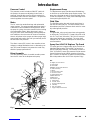 3
3
-
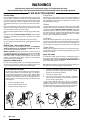 4
4
-
 5
5
-
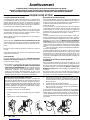 6
6
-
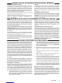 7
7
-
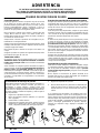 8
8
-
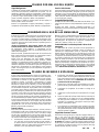 9
9
-
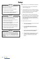 10
10
-
 11
11
-
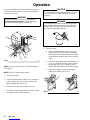 12
12
-
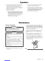 13
13
-
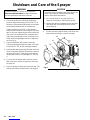 14
14
-
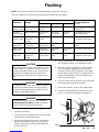 15
15
-
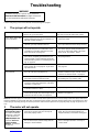 16
16
-
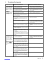 17
17
-
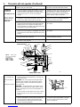 18
18
-
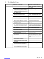 19
19
-
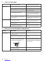 20
20
-
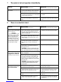 21
21
-
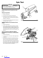 22
22
-
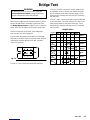 23
23
-
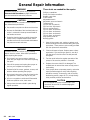 24
24
-
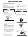 25
25
-
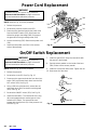 26
26
-
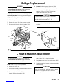 27
27
-
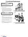 28
28
-
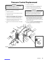 29
29
-
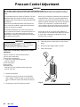 30
30
-
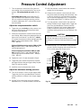 31
31
-
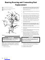 32
32
-
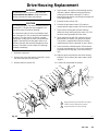 33
33
-
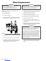 34
34
-
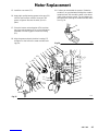 35
35
-
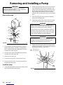 36
36
-
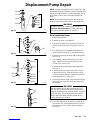 37
37
-
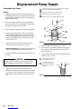 38
38
-
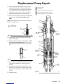 39
39
-
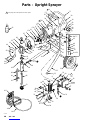 40
40
-
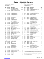 41
41
-
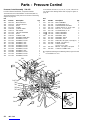 42
42
-
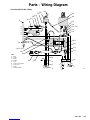 43
43
-
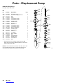 44
44
-
 45
45
-
 46
46
-
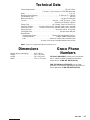 47
47
-
 48
48


Graco 231-043 Instructions and Parts List
- Catégorie
- Pulvérisateur de peinture
- Taper
- Instructions and Parts List
dans d''autres langues
- English: Graco 231-043
- español: Graco 231-043
Documents connexes
-
Graco 220-886 Instructions and Parts List
-
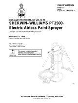 Sherwin-Williams PT2500 Manuel utilisateur
-
-
Graco Inc. 1595 HI Manuel utilisateur
-
-
Graco 257093 Manuel utilisateur
-
Hitachi 311254E - Silver and Flex Plus Airless Spray Guns Manuel utilisateur
-
