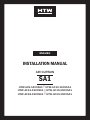
HTW CORTINA DE AIRE SA1 Manuel utilisateur
- Taper
- Manuel utilisateur

SA1
HTW-AC9-1400SA1 | HTW-AC10-1600SA1
HTW-AC12-1900SA1 | HTW-AC15-2500SA1
HTW-AC18-3200SA1 | HTW-AC20-3600SA1
CORTINA DE AIRE | AIR CURTAIN | RIDEAU D’AIR
CORTINA DE AR | CORTINA D’ARIA
EN
FR
PT
IT
MANUAL DE INSTALACIÓN
INSTALLATION MANUAL
MANUEL D’INSTALLATION
MANUAL DO INSTALAÇÃO
MANUALE DI INSTALLAZIONE
ES
Por favor lea atentamente este manual antes de usar este producto.
Please, read carefully this manual before using the product.
Avant d’utiliser l’équipement, lisez attentivement les instructions.
Por favor leia atentamente este manual antes de usar o equipamento.
Per favore leggere attentamente questo manuale prima di utilizzare questo prodotto.
Gracias | Thank you | Merci | Obrigado | Grazie

MANUAL DE
INSTALACIÓN
ESPAÑOL
SA1
CORTINA DE AIRE
HTW-AC9-1400SA1 | HTW-AC10-1600SA1
HTW-AC12-1900SA1 | HTW-AC15-2500SA1
HTW-AC18-3200SA1 | HTW-AC20-3600SA1

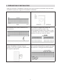
1. INTRODUCCIÓN DE PRODUCTO
Las cortinas de aire son un elemento muy importante en la climatización de locales puesto
que las aperturas que éste tenga hacia el exterior suponen una gran pérdida de la eciencia.
Mediante la instalación de una cortina de aire en la entrada de bares, tiendas, supermerca-
dos, ocinas, etc, creamos una barrera de aire que impide que la temperatura del local se vea
afectada por la temperatura exterior. Además previene la entrada de suciedad, insectos, etc.
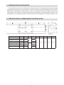
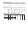
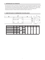
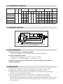
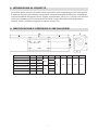
2. IDENTIFICACIÓN Y DIMENSIONES DE INSTALACIÓN
MODELO A B C D F G H I J
HTW-AC9-1400SA1 900 330 ---
HTW-AC10-1600SA1 1000 380 440 ---
HTW-AC12-1900SA1 1200 480 --- 55 90 210 190 110
HTW-AC15-2500SA1 1500 330 ---
HTW-AC18-3200SA1 1800 480 840 ---
HTW-AC20-3600SA1 2000 580 ---
1

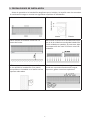
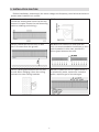
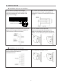
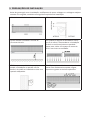
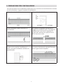
3. PRECAUCIONES DE INSTALACIÓN
Antes de proceder a la instalación asegúrese que el voltaje y la tensión sean los correctos.
A continuación tenga en cuenta los siguientes requisitos de instalación:
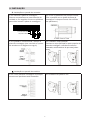
3.1 Instale la unidad en el interior del local. 3.2 Instale la unidad en el interior del local.
3.3 No instale la unidad a menos de 2.3
metros del suelo.
3.4 Cuando el ancho de la entrada sea mayor
que el de la unidad se recomienda instalar dos
o más unidades en paralelo. En este caso, deje
una separación de unos 20-40mm entre las
unidades.
3.5 No separe la unidad de la pared. Cuando
no sea posible la instalación en la pared,
ésta puede ser instalada en el techo con los
soportes adecuados.
3.6 No instale la unidad en un lugar donde
pueda ser expuesta directamente a agua,
vapores o gases corrosivos-explosivos.
2

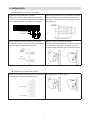
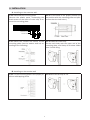
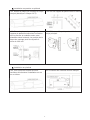
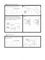
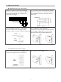
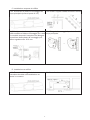
4. INSTALACIÓN
A. Instalación en muro de hormigón:
B. Instalación en pared de madera
4.1.1 Extraer la placa de montaje
Retire los tornillos de la parte trasera de la
unidad y a continuación extraiga los plásticos
para poder acceder a la placa de montaje.
1
2
PLACA DE MONTAJE
2
1
PARTES PLÁSTICAS
4.1.2 Fije los tornillos en la posición correcta
(je la posición con la ayuda de la placa de
montaje y vierta cemento en los agujeros de
los tornillos.)
4.1.3 Cuando se haya secado el cemento,
encaje la placa de montaje (utilice arandela y
tuerca según el siguiente esquema)
4.1.4 4 Instale el cuerpo principal
Posicione el cuerpo principal en la parte superior
de la placa de montaje y encájelo como se
muestra, asegurándose que quede bien jado.
4.2.1 Fije la placa de montaje en la posición
correcta con tornillos autorroscantes.
4.2.2 Igual que el paso 4.1.4.
3

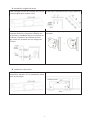
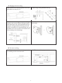
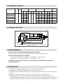
C. Instalación colgada del techo
D. Instalación sobre techo
4.3.1 Extraiga la placa de montaje del cuerpo
principal (Igual que el paso 4.1.1)
4.3.2 Fije los soportes de techo según esquema:
4.3.3 Coloque la placa de montaje sobre los
soportes de techo y asegure su jación con
las tuercas y arandelas según su muestra en
el dibujo. La posición de la placa de mon-
taje puede ser ajustada con un margen de
100mm.
4.3.4 Realice el paso A para instalar el cuerpo
principal.
4.4.1 Fije la unidad siguiendo el mismo pro-
cedimiento descrito en la instalación sobre
muro de hormigón.
4.4.2 Instale los conductos como se muestra:
4

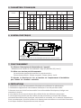
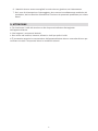
5. PARÁMETROS TÉCNICOS
6. ESQUEMA ELÉCTRICO
7. FUNCIONAMIENTO
7.1 Active el interruptor de encendido de la unidad.
Seleccione la velocidad de aire deseada: Alta [H], Media [M], Baja [L]
7.2 Encendido mediante el control remoto.
Se utiliza un único botón para controlar el ciclo de funcionamiento:
Encendido a velocidad máxima – Velocidad Media – Baja velocidad – Apagado.
7.3 Ajuste la dirección del aire de acuerdo al lugar de instalación para conseguir
los resultados deseados.
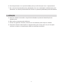
8. PRECAUCIONES
1. Desconecte la unidad de la alimentación eléctrica para realizar los mantenimientos.
2. Desconecte la unidad de la alimentación eléctrica si ésta no va a ser utilizada.
3. Asegúrese de que la unidad es conectada a la alimentación que incorpore toma de tierra.
4. Los dibujos del presente manual deben ser utilizados únicamente como referencia.
5. Este equipos no debe ser usado por personas (incluyendo niños) con reducciones físicas,
sensoriales o mentales, o con falta de experiencia y conocimiento a no ser que lo realicen
bajo supervisión o instrucciones acerca del uso del equipo con seguridad.
THERMAL CUT-OUT
DOUBLE SPEED SWITCH WIRING DIAGRAM
YELLOW-GREEN
(YELLOW)
BLACK
WHITE
BLUE(BROWN/RED)
YELLOW
ORANGE
C
K
2OFF
3HI
1LO
L
N
DIAGRAMA DE CABLEADO CON CONTROL REMOTO POR INFRARROJOS DE DOBLE VELOCIDAD
CORTE TÉRMICO AMARILLO-VERDE
BLANCO
AZUL (MARRÓN/ROJO)
C
AMARILLO
NEGRO
(AMARILLO)
NARANJA
RECEPTOR
I/C
GRIS
BLANCO
N
L
MARRÓN
AZUL
Consumo máximo
(W)
Velocidad máxima
(m/s)
Volumen de aire Nivel sonoro Peso neto
MODELO Volt. Freq (m3/h) (dB) (Kg)
(V~) (Hz)
H M L H M L H M L H M L
HTW-AC9-1400SA1 160 110 70 1.400 1.100 900 57 55 53 10
HTW-AC10-1600SA1 180 130 90 1.600 1.300 1000 57 55 53 10,5
HTW-AC12-1900SA1 200 150 110 1.900 1.600 1.200 58 56 54 12
11 9 7
HTW-AC15-2500SA1 220 50 230 180 140 2.500 2.000 1.500 59 57 55 13,5
HTW-AC18-3200SA1 300 250210 3.200 2.500 1.800 60 58 56 15
HTW-AC20-3600SA1 350 300260 3.600 2.700 1.850 61 59 57 18
RECEPTOR
I/C
5

6. Los niños deben ser supervisados para que no jueguen con el equipo.
7. Si el cable de alimentación está dañado, éste debe ser reemplazado inmediatamente por
el fabricante, su Servicio de Asistencia técnica o por personal cualicado con el n de
evitar daños.
9. ATENCIÓN
a. Utilice la unidad al voltaje y la frecuencia indicados en la placa de características del equipo.
b. No moje los componentes eléctricos.
c. Nunca utilice gasolina, benceno, disolventes ni similares para limpiar la unidad.
d. Debe realizar un mantenimiento del equipo como mínimo una vez cada año para vericar
que todos los componentes se encuentran en óptimo estado.
6

INSTALLATION MANUAL
ENGLISH
SA1
AIR CURTAIN
HTW-AC9-1400SA1 | HTW-AC10-1600SA1
HTW-AC12-1900SA1 | HTW-AC15-2500SA1
HTW-AC18-3200SA1 | HTW-AC20-3600SA1

1. PRODUCT INTRODUCTION
As one of the new top-class products for modern decoration, air curtain is also matched with
the air-conditioner. And it is installed at the entrances of supermarket, theater, meeting room,
hotel, ofce room, and storeroom to prevent the dust, mosquito and warm air, and so on.
2. IDENTIFICATION & INSTALLATION DIMENSIONS
MODEL A B C D F G H I J
HTW-AC9-1400SA1 900 330 ---
HTW-AC10-1600SA1 1000 380 440 ---
HTW-AC12-1900SA1 1200 480 --- 55 90 210 190 110
HTW-AC15-2500SA1 1500 330 ---
HTW-AC18-3200SA1 1800 480 840 ---
HTW-AC20-3600SA1 2000 580 ---
1

3. INSTALLATION CAUTION
Before installation, please apply the same voltage and frequency, then follow the below re-
quests when install the air curtain:
3.1 Please install the unit in a sturdy place
to avoid the shaking and ensure its security
(because it maybe causes the wall becoming
exible or shaking and noising.)
3.2 Please install the unit inside the room.
3.3 Don’t install the unit too low, no less
than 2.3 meters from the ground.
3.4 When the entrance is wider than the
unit, it is recommended to install two or more
units in parallel. In this case, provide 20-
40mm gaps between the units.
3.5 Don’t allow gaps between the unit and
the wall. When hanging it from the ceiling,
purchase the extra ceiling brackets.
3.6 Don’t install the unit in a place where it
is splashed by water, exposed to excessive
steam, explosive gas or corrosive gas.
2

4. INSTALLATION
A. Installing on the concrete wall:
B. Installing on the wooden wall
4.1.1 Removed the mounting plate
Remove the plastic parts, unclamping the
xed screws on the back of main body to re-
move the mounting plate.
1
2
MOUNTING PLATE
2
1
PLASTIC PARTS
4.1.2 Fix the bolts in the proper position (x
the position with the mounting plate and pour
cement into the bolt holes.)
4.1.3 When the cement has freeze, t the
mounting plate (use the washer and nut ac-
cording to the following)
4.1.4 Install the main body
Set the main body onto the upper end of the
mounting plate, and clamp it as below. Make
sure it’s well xing
4.2.1 Fix the mounting plate in the proper po-
sitions with tapping screw.
4.2.2 Same as the step 4.1.4.
3

C. Hanging from the ceiling
D. For above ceiling
4.3.1 Remove the mounting plate from main
body (Same as step 4.1.1)
4.3.2 Fixing ceiling brackets as Fig.
4.3.3 Set the mounting plate on the ceiling
brackets and ensure safety & xing (use the
bolts attached to the ceiling brackets as Fig.
Using the ceiling brackets to hang from the
ceiling, the position of mounting plate can be
adjusted in the limit of 100 mm. washer and
nut according to the following)
4.3.4 Do the same as step A to install the
main body.
4.4.1 Fix the air curtain as in the procedure
for installing on the concrete wall.
4.4.2 Then install the pipe as below.
4

5. TECHNICAL PARAMETER
6. ELECTRIC WORK
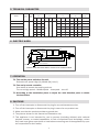
7. OPERATION
7.1 Turn on the power switch on the unit.
Select the air speed: High [H], Middle [M], Low [L]
7.2 Turn on by remote controller.
One button to control the working cycle at:
Turn on at high speed – Middle speed – Low speed – turn off.
7.3 According to the installation place to adjust the wind direction parts to obtain
the best effect.
8. CAUTIONS
1. Turn off the interrupter or disconnect the plug for any maintenance service.
2. Turn off the interrupter or disconnect the plug in case of a non product use.
3. Make sure that the product provides a ground wire.
4. The pictures shown on this manual are illustrative only.
5. This appliance is not intended for use by persons (including children) with reduced
physical, sensory or mental capabilities, or lack of experience and knowledge, unless
they have been given supervision or instruction concerning use of the appliance by a per
son responsible for their safety.
THERMAL CUT-OUT
DOUBLE SPEED SWITCH WIRING DIAGRAM
YELLOW-GREEN
(YELLOW)
BLACK
WHITE
BLUE(BROWN/RED)
YELLOW
ORANGE
C
K
2OFF
3HI
1LO
L
N
DOUBLE SPEED INFRARED REMOTE CONTROLLED WIRING DIAGRAM
THERMAL CUT-OUT YELLOW-GREEN
WHITE
RECEIVER
I/O
BLUE(BROWN/RED)
C
YELLOW
BLACK
(YELLOW)
ORANGE
RECEIVER
I/C
GREY
WHITE
N
L
BROWN
BLUE
Max input power Max air speed Air volume Noise Net weight
MODEL Volt. Freq (W) (m/s) (m3/h) (dB) (Kg)
(V~) (Hz)
H M L H M L H M L H M L
HTW-AC9-1400SA1 160 110 70 1.400 1.100 900 57 55 53 10
HTW-AC10-1600SA1 180 130 90 1.600 1.300 1000 57 55 53 10,5
HTW-AC12-1900SA1 200 150 110 1.900 1.600 1.200 58 56 54 12
HTW-AC15-2500SA1 220 50 11 9 7
230 180 140 2.500 2.000 1.500 59 57 55 13,5
HTW-AC18-3200SA1 300 250210 3.200 2.500 1.800 60 58 56 15
HTW-AC20-3600SA1 350 300260 3.600 2.700 1.850 61 59 57 18
5

6. Children should be supervised to ensure that they do not play with the appliance.
7. If the supply cord is damaged, it must be replaced by the manufacturer, its service agent
or similarly qualied persons in order to avoid a hazard.
9. ATTENTION
a. Use the unit at the rated voltage and frequency indicated on the nameplate.
b. Do not wet the product electrical components.
c. Never use petrol, benzene, thinners or any other such chemical to clean the unit.
d. Routine maintenance must be done every year.
6

SA1
MANUEL D’INSTALLATION
FRANÇAIS
RIDEAU D’AIR
HTW-AC9-1400SA1 | HTW-AC10-1600SA1
HTW-AC12-1900SA1 | HTW-AC15-2500SA1
HTW-AC18-3200SA1 | HTW-AC20-3600SA1

1. PRÉSENTATION DU PRODUIT
Les rideaux d'air sont un élément très important dans la climatisation des locaux car les
ouvertures qu'il a vers l'extérieur signifient une grande perte d'efficacité. En installant un
rideau d'air à l'entrée des bars, magasins, supermarchés, bureaux, etc., nous créons un pare-
air qui empêche la température des locaux d'être affectée par la température extérieure. Il
empêche également l'entrée de saleté, d'insectes, etc.
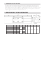
2. IDENTIFICATION ET COTES D'INSTALLATION
MODÈLE A B C D F G H I J
HTW-AC9-1400SA1 900 330 ---
HTW-AC10-1600SA1 1000 380 440 ---
HTW-AC12-1900SA1 1200 480 --- 55 90 210 190 110
HTW-AC15-2500SA1 1500 330 ---
HTW-AC18-3200SA1 1800 480 840 ---
HTW-AC20-3600SA1 2000 580 ---
1

3. PRÉCAUTIONS D'INSTALLATION
Avant de procéder à l'installation, assurez-vous que la tension et la tension sont correctes.
Considérez ensuite les exigences d'installation suivantes:
3.1 Installer l'unité à l'intérieur. 3.2 Installer l'unité à l'intérieur.
3.3 N'installez pas l'unité à moins de 2,3
mètres du sol.
3.4 Lorsque la largeur de l'entrée est
supérieure à celle de l'unité, il est
recommandé d'installer deux unités ou plus
en parallèle. Dans ce cas, laissez un espace
d'environ 20-40 mm entre les unités.
3.5 Ne séparez pas l'appareil du mur.
Lorsque l'installation murale n'est pas
possible, il peut être installé au plafond avec
des supports appropriés.
3.6 N'installez pas l'appareil dans un endroit
où il peut être directement exposé à de l'eau,
des vapeurs ou des gaz corrosifs-explosifs.
2

4. INSTALLATION
A. Installation dans un mur en béton :
B. Installation sur mur en bois
4.1.1 Retirer la plaque de montage
Retirez les vis à l'arrière de l'unité, puis
retirez les plastiques pour accéder à la
plaque de montage.
1
2
PLAQUE DE MONTAGE
2
1
PIÈCES EN PLASTIQUE
4.1.2 Fixez les vis dans la bonne position
(Fixez la position à l'aide de la plaque de
montage et versez du ciment dans les trous
de vis.)
4.1.3 Lorsque le ciment a séché, monter la
plaque de montage (utiliser la rondelle et
l'écrou selon le schéma suivant)
4.1.4 4 Installer le corps principal
Placez le corps principal au-dessus de la
plaque de montage et enclenchez-le comme
indiqué, en vous assurant qu'il est solidement
fixé.
4.2.1 Fixez la plaque de montage dans la
bonne position avec des vis
autotaraudeuses.
4.2.2 Identique à l'étape 4.1.4.
3

C. Installation suspendue au plafond
D. Installation au plafond
4.3.1 Retirez la plaque de montage du corps
principal (Identique à l'étape 4.1.1)
4.3.2 Fixer les supports de plafond selon le schéma:
4.3.3 Placer la plaque de montage sur les
supports de plafond et sécuriser sa fixation
avec les écrous et rondelles selon votre
échantillon dans le dessin. La position de la
plaque de montage peut être ajustée à
moins de 100 mm.
4.3.4 Effectuez l'étape A pour installer le
corps principal.
4.4.1 Fixer l'unité en suivant la même
procédure décrite dans l'installation sur un
mur en béton.
4.4.2 Installer les conduits comme indiqué:
4
La page est en cours de chargement...
La page est en cours de chargement...
La page est en cours de chargement...
La page est en cours de chargement...
La page est en cours de chargement...
La page est en cours de chargement...
La page est en cours de chargement...
La page est en cours de chargement...
La page est en cours de chargement...
La page est en cours de chargement...
La page est en cours de chargement...
La page est en cours de chargement...
La page est en cours de chargement...
La page est en cours de chargement...
La page est en cours de chargement...
La page est en cours de chargement...
La page est en cours de chargement...
-
 1
1
-
 2
2
-
 3
3
-
 4
4
-
 5
5
-
 6
6
-
 7
7
-
 8
8
-
 9
9
-
 10
10
-
 11
11
-
 12
12
-
 13
13
-
 14
14
-
 15
15
-
 16
16
-
 17
17
-
 18
18
-
 19
19
-
 20
20
-
 21
21
-
 22
22
-
 23
23
-
 24
24
-
 25
25
-
 26
26
-
 27
27
-
 28
28
-
 29
29
-
 30
30
-
 31
31
-
 32
32
-
 33
33
-
 34
34
-
 35
35
-
 36
36
-
 37
37


HTW CORTINA DE AIRE SA1 Manuel utilisateur
- Taper
- Manuel utilisateur
dans d''autres langues
- italiano: HTW CORTINA DE AIRE SA1 Manuale utente
- español: HTW CORTINA DE AIRE SA1 Manual de usuario
- português: HTW CORTINA DE AIRE SA1 Manual do usuário