Simplicity Wireless Gateway Guide d'installation
- Taper
- Guide d'installation

Wireless Gateway Module
for use with Amplify™ Power Management System
Installation and Operation Instructions
Questions?
Help is just a moment away!
Call our Helpline:
(800) 732-2989 M-F 8-5 CT
© Briggs & Stratton
All Rights Reserved. 80079547
Revision C
Not for
Reproduction

2 BRIGGSandSTRATTON.COM
Save These Instructions
Important Safety Instructions
SAVE THESE INSTRUCTIONS - This manual contains
important instructions that should be followed during
installation and maintenance of the generator and
batteries.
Safety Symbols and Meanings
The safety alert symbol indicates a potential personal
injury hazard. A signal word (DANGER, WARNING, or
CAUTION) is used with the alert symbol to designate a
degree or level of hazard seriousness. A safety symbol
may be used to represent the type of hazard. The signal
word NOTICE is used to address practices not related to
personal injury.
DANGER
indicates a hazard which, if not avoided, will
result in death or serious injury.
WARNING
indicates a hazard which, if not avoided,
could result in death or serious injury.
CAUTION
indicates a hazard which, if not avoided,
could result in minor or moderate injury.
NOTICE
Addresses practices not related to personal injury
The manufacturer cannot anticipate every circumstance
that might involve a hazard. The warnings in this manual,
and the tags and decals affixed to the unit are, therefore,
not all-inclusive. If you use a procedure, work method
or operating technique that the manufacturer does not
specifically recommend, you must satisfy yourself that it is
safe for you and others. You must also make sure that the
procedure, work method or operating technique that you
choose does not render the generator system unsafe.
NOTICE Improper treatment of equipment could damage it
and shorten its life.
• Use equipment only for intended uses.
• If you have questions about intended use, ask dealer or
contact Briggs & Stratton.
• Do not expose equipment to excessive moisture, dust, dirt, or
corrosive vapors.
• Remain alert at all times while working on this equipment.
Never work on the equipment when you are physically or
mentally fatigued.
• If connected devices overheat, turn them off and turn off their
circuit breaker/fuse.
Read ManualElectrical Shock
WARNING Shock Hazard. Installing low and high voltage
wire in same conduit could result in death, serious
injury and/or property damage.
• Do not run low and high voltage wire in the same conduit
unless the insulation rating on ALL wiring is rated for 600V.
See NEC for more information.
WARNING Failure to properly ground equipment could
cause electrocution resulting in death or serious injury.
• Do not touch bare wires.
• Do not use equipment with worn, frayed, bare or otherwise
damaged wiring.
• Do not handle electrical cords while standing in water, while
barefoot, or while hands or feet are wet.
• If you must work around a unit while it is operating, stand on
an insulated dry surface to reduce shock hazard.
• Do not allow unqualified persons or children to operate or
service equipment.
• In case of an accident caused by electrical shock, immediately
shut down all sources of electrical power and contact local
authorities. Avoid direct contact with the victim.
WARNING Equipment contains high voltage that could
cause electrocution resulting in death or serious injury.
• Despite the safe design of the system, operating this
equipment imprudently, neglecting its maintenance or being
careless could result in death or serious injury.
WARNING
This product contains lead and lead
compounds, known to the state of California to cause
birth defects or other reproductive harm. Wash
your hands after handling this product. Cancer and
Reproductive Harm - www.P65Warnings.ca.gov
Not for
Reproduction

3
NOTICE FCC Part 15 Information to User
Pursuant to part 15.21 of the FCC Rules, you are cautioned
that changes or modifications not expressly approved by
Briggs and Stratton could void your authority to operate the
device.
This device complies with part 15 of the FCC Rules.
Operation is subject to the following two conditions: (1) This
device may not cause harmful interference, and (2) this
device must accept any interference received, including
interference that may cause undesired operation.
This equipment has been tested and found to comply with
the limits for a Class B digital device, pursuant to part 15
of the FCC Rules. These limits are designed to provide
reasonable protection against harmful interference in a
residential installation. This equipment generates, uses
and can radiate radio frequency energy and, if not installed
and used in accordance with the instructions, may cause
harmful interference to radio communications. However,
there is no guarantee that interference will not occur in a
particular installation. If this equipment does cause harmful
interference to radio or television reception, which can be
determined by turning the equipment off and on, the user is
encouraged to try to correct the interference by one or more
of the following measures:
—Reorient or relocate the receiving antenna.
—Increase the separation between the equipment and
receiver.
—Connect the equipment into an outlet on a circuit different
from that to which the receiver is connected.
—Consult the dealer or an experienced radio/TV technician
for help.
NOTICE IC Information to User
This device complies with Industry Canada’s licence-exempt
RSSs. Operation is subject to the following two conditions:
(1) This device may not cause interference; and
(2) This device must accept any interference, including
interference that may cause undesired operation of the
device.
NOTICE FCC RF Radiation Exposure Statement to User
This equipment complies with FCC radiation exposure
limits set forth for an uncontrolled environment. End users
must follow the specific operating instructions for satisfying
RF exposure compliance. This device meets exposure
limits as demonstrated in a RF Exposure Analysis. The
device must be installed such that a minimum separation
distance of 20 cm is maintained between the device and all
persons at all times.
General Information
Equipment Description
This product is intended only for use as an optional
generator-system wireless control source for the owner.
It allows one to set priorities of assigned loads such as
heating, refrigeration systems, and communication systems
that are controlled by the generator. It also provides
generator status information to the InfoHub™ Cloud.
Where To Find Us
You never have to look far to find support and service for
your generator. Consult your Yellow Pages. There are many
authorized service dealers worldwide that provide quality
service. You can also contact Technical Service by phone
at
800-732-2989 between 8:00 AM and 5:00 PM central time
or click on Dealer Locator at www.briggsandstratton.com,
which provides a list of authorized dealers.
Product Specifications
Rated Voltage ............................................................12V DC
Normal Operating Range .....-20°F (-28.8°C) to 104°F (40°C)
Weight .......................................................0.81 lbs. (0.37 kg)
* This device is listed with UL (Underwriters Laboratories).
Please fill out the information below and keep your receipt to
assist in unit identification for future purchase issues.
Model Number
_______________
Revision
_______________
Serial Number
_______________
Date Purchased
_______________
Before Installation
Only current licensed electrical professionals should
attempt wireless module installations. Installations must
strictly comply with all applicable codes, industry standards,
laws, and regulations.
In some areas you may need electrical permits for installing
wireless modules. The installer should check local codes
and obtain the necessary permits before installing the
module.
The gateway wireless module warranty is VOID unless the
module is installed by licensed electrical professionals.
Installer Responsibilities
• Read and observe the safety instructions.
• Read and follow the instructions in this installation
and operation manual.
• Installation must strictly comply with all applicable
codes, industry standards, laws, and regulations.
• Allow sufficient room on all sides of the wireless
module for maintenance and servicing.
Not for
Reproduction

4 BRIGGSandSTRATTON.COM
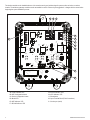
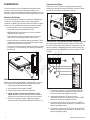
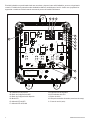
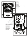
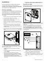
A • Power Indicator LED
B • WiFi Configuration button
C • Device Configuration button
D • Mode LED
E • WiFi Indicator LED
F • RS-485 Indicator LED
G • Device Indicator LED
H • CPU Indicator LED
J • Reset button
K • Input Terminal Block (Field Connections)
L • Service port (serial)
The wireless module can be installed wherever it is convenient and a good wireless signal is present, either an indoor or outdoor
location. The
wireless gateway module
must be accessible for service. Discuss layout suggestions / changes with the owner before
beginning the system installation process.
VIN+ D+ D- GND
Power
WiFi
Mode
RS-485
Device
CPU
WiFi
Config
Device
Config E
D
F
G
H
L
A B C
K
J
Figure 1
Not for
Reproduction

5
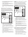
A • L1 IN
B • L2/N IN
C • 230VAC N
D • Ground
E • L1 OUT
F • L2/N OUT
G • Network Configuration Button (Join)
H • Power LED
J • Relay LED
K • Fault LED
L • Network LED
A • 24VAC Power Input
B • Network Configuration Button (Join)
C • Load #2 Output
D • Load #1 Output
E • Fault LED
F • Network LED
G • Power LED
H • Output 2 LED
J • Output 1 LED
G
B A EF C
L2/N OUT L1 OUTL2/N IN L1 IN 230VAC N 230VAC N
D
J K L
H
Figure 2
A
CD
B
EG
HJ
F
Figure 3
Not for
Reproduction

6 BRIGGSandSTRATTON.COM
Installation
It is recommended to use an 18AWG double-twisted shielded
pair wire to connect the
wireless gateway module
to the
generator. This wire is available from Briggs and Stratton. For more
information please visit our website at
www.briggsandstratton.com
.
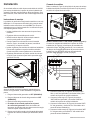
Mounting Guidelines
The power management modules are contained in a NEMA Type
4 enclosure. The wireless gateway module components are
contained in a NEMA Type 3R enclosure that is suitable for indoor/
outdoor use. The guidelines for mounting the enclosure include:
• Install enclosure on a firm, sturdy supporting structure.
• The enclosure must be accessible for service.
• NEVER install the device where any corrosive substance
might drip onto the enclosure.
• Protect the device at all times against excessive moisture,
dust, dirt, lint, construction grit and corrosive vapors.
• Install an enclosure to maximize wireless performance. Avoid
mounting the enclosure inside confined metal spaces. When
possible, mount enclosure in open area.
• The enclosure must be mounted vertically so that the grommet
(A, Figure 4 ) is on the bottom to prevent water from entering
the enclosure.
Figure 4
A
Disconnect the Power
Before performing any installation, maintenance, or service
on the generator, ALWAYS perform the following steps:
1. Set generator system switch to OFF.
2. Set generator circuit breaker to OFF.
3. Remove the fuse from the main generator.
4. Utility voltage is present at generator control
panel. Remove the fuses from the transfer switch to
disconnect power before servicing the control panel.
5. Disconnect negative battery cable from negative
battery terminal, indicated by NEGATIVE, NEG, or (-).
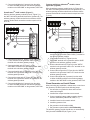
Connect the Wires
Remove the cover (A, Figure 5) from the
wireless gateway
module
by loosening the screws (B) DO NOT remove the rubber
grommet (C) from the hole in the bottom of the box.
Figure 5
C
A
B
B
B
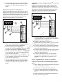
PowerProtect 17kW, 20kW and 26kW models (Figure 6):
Wire the wireless gateway module inputs (A, Figure 6) to
the “WiFi” field wiring terminal blocks
of the generator (B). The
wireless gateway module
terminal block connections and the
generator terminal block connections must be torqued to 0.5 Nm
(4.4 in-lb).
Figure 6
VIN+ D+ D- GND
9
11
12
13
15
16
(B)
+12V
(A)
GND
+12V
(B)
(A)
GND
W
I
F
I
C
E
L
L
U
L
A
R
10
14
VIN+ D+ D- GND
9
11
12
13
15
16
GND
+12V
(B)
(A)
GND
W
I
F
I
C
E
L
L
U
L
A
R
10
14
VIN+ D+ D- GND
9
11
12
13
15
16
GND
+12V
(B)
(A)
GND
W
I
F
I
C
E
L
L
U
L
A
R
10
14
FortressPower Protect 17, 20, 26kW Power Protect 12kW Only
AB
C
D
E
F
AB
C
D
E
F
AB
C
DE
F
1. Connect the red wire (C, Figure 6) to the “WiFi VIN+
(+12V)” terminal on the generator and the “VIN(+)”
terminal on the wireless gateway module.
2. Connect the black wire (F, Figure 6) to the
“WiFi GND” terminal on the generator and the “GND”
terminal on the wireless gateway module.
3. Connect the white wire (D, Figure 6) to the “WiFi D+”
terminal on the generator and the “D+” terminal on the
wireless gateway module.
4. Connect the orange wire (E, Figure 6) to the “WiFi D-”
terminal on the generator and the “D-” terminal on the
wireless gateway module.
Not for
Reproduction

7
5. Connect the shield wire (if present) from the cable
to either the GND terminal on the wireless gateway
module or the “WiFi GND” on the generator, NOT both.
PowerProtect™ 12kW models (Figure 7):
Wire the wireless gateway module inputs (A, Figure 7) to
the “WiFi” field wiring terminal blocks
of the generator (B). The
wireless gateway module
terminal block connections and the
generator terminal block connections must be torqued to 0.5 Nm
(4.4 in-lb).
Figure 7
VIN+ D+ D- GND
9
11
12
13
15
16
(B)
+12V
(A)
GND
+12V
(B)
(A)
GND
W
I
F
I
C
E
L
L
U
L
A
R
10
14
VIN+ D+ D- GND
9
11
12
13
15
16
GND
+12V
(B)
(A)
GND
W
I
F
I
C
E
L
L
U
L
A
R
10
14
VIN+ D+ D- GND
9
11
12
13
15
16
GND
+12V
(B)
(A)
GND
W
I
F
I
C
E
L
L
U
L
A
R
10
14
FortressPower Protect 17, 20, 26kW Power Protect 12kW Only
AB
C
D
E
F
AB
C
D
E
F
AB
C
DE
F
1. Connect the red wire (C, Figure 7) to the “WiFi VIN+
(+12V)” terminal on the generator and the “VIN(+)”
terminal on the wireless gateway module.
2. Connect the black wire (F, Figure 7) to the
“WiFi GND” terminal on the generator and the “GND”
terminal on the wireless gateway module.
3. Connect the white wire (D, Figure 7) to the “WiFi D+”
terminal on the generator and the “D+” terminal on the
wireless gateway module.
4. Connect the orange wire (E, Figure 7) to the “WiFi D-”
terminal on the generator and the “D-” terminal on the
wireless gateway module.
5. Connect the shield wire (if present) from the cable
to either the GND terminal on the wireless gateway
module or the “WiFi GND” on the generator, NOT both.
Fortress and Briggs & Stratton® models, where
applicable (Figure 8):
Wire the wireless gateway module inputs (A, Figure 8) to
the “WiFi” field wiring terminal blocks
of the generator (B). The
wireless gateway module
terminal block connections and the
generator terminal block connections must be torqued to 0.5 Nm
(4.4 in-lb).
Figure 8
VIN+ D+ D- GND
9
11
12
13
15
16
(B)
+12V
(A)
GND
+12V
(B)
(A)
GND
W
I
F
I
C
E
L
L
U
L
A
R
10
14
VIN+ D+ D- GND
9
11
12
13
15
16
GND
+12V
(B)
(A)
GND
W
I
F
I
C
E
L
L
U
L
A
R
10
14
VIN+ D+ D- GND
9
11
12
13
15
16
GND
+12V
(B)
(A)
GND
W
I
F
I
C
E
L
L
U
L
A
R
10
14
FortressPower Protect 17, 20, 26kW Power Protect 12kW Only
AB
C
D
E
F
AB
C
D
E
F
AB
C
DE
F
1. Connect the red wire (C, Figure 8) to the “WiFi +12V”
terminal on the generator and the “VIN(+)” terminal on
the wireless gateway module.
2. Connect the black wire (F, Figure 8) to the
“WiFi GND” terminal on the generator and the “GND”
terminal on the wireless gateway module.
3. Connect the white wire (D, Figure 8) to the “WiFi A”
terminal on the generator and the “D+” terminal on the
wireless gateway module.
4. Connect the orange wire (E, Figure 8) to the “WiFi B”
terminal on the generator and the “D-” terminal on the
wireless gateway module.
5. Connect the shield wire (if present) from the cable
to either the GND terminal on the wireless gateway
module or the “WiFi GND” on the generator, NOT both.
Close Generator and Install Fuses
After performing any installation, maintenance, or service on
the generator, ALWAYS perform the following steps:
1. Use wire ties to organize the wires and to secure
excess wire lengths.
2. Install all the components that were removed.
3. Connect negative battery cable to negative battery
terminal, indicated by NEGATIVE, NEG, or (-).
4. Install the fuses into the transfer switch.
5. Install the generator fuse.
6. Set generator circuit breaker to ON.
7. Set generator system switch to AUTO/Standby.
The wireless gateway module should turn on automatically.
Verify that the POWER LED (A, Figure 1) is on.
Not for
Reproduction

8 BRIGGSandSTRATTON.COM
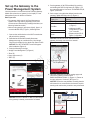
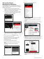
Set up the Gateway to the
Power Management System
Use this procedure to connect the InfoHub™ Wireless Gateway
Module (also referred to as “gateway”) to the Amplify™ Power
Management System for wireless connection.
Before you start:
• Put
gateway
within range of the Power Management
System. Exact range will vary depending on the home
environment and determined by installing technicians (see
Mounting Guidelines section).
• Make sure the gateway’s green power light (A, figure 1) is
on and the MODE LED (D, Figure 1) flashes light blue.
1. Connect the mobile device to the Wi-Fi network that
will pair with the gateway.
2. Download and install the Standby Generator
Management app to a mobile device. Use Google
Play Store for Android or the Apple Play Store for iOS.
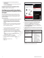
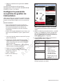
NOTICE: The “GET STARTED” screen will appear
after installation (Figure 9).
3. Push the following in the app:
• “Amplify Power Management” (A, Figure 9).
• “Enter” (B)
• Upper-right menu (C)
• "WiFi" (D)
D
A
C
B
Figure 9
NOTICE: The icon to the left of “WiFi” (D) will change
if the gateway is already connected to a network
4. Put the gateway in “Wi-Fi Direct Mode” by pushing
and holding the WiFi Config button (B, Figure 1) on
the gateway board for 5 seconds. The MODE LED (D,
Figure 1) will flash.
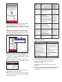
5. Do the steps in the table that follows based on the
gateway’s Mode LED light color (D, Figure 1).
If MODE LED (D,
Figure 1) is:
Do the following on the
gateway:
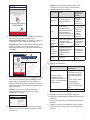
Light Blue Press YES (A, Figure 10)
Dark Blue
• Press the Reset button
(J, Figure 1).
• Hold down the WiFi
Config button (B, Figure
1) for 5 seconds.
• Repeat until the LED (D,
Figure 1) is light blue.
Red
Green
NOTICE: Dark Blue & Green indicate that the
gateway is already connected to a network.
A
Figure 10
6. Open the mobile device’s Wi-Fi settings page and
choose the following network name:
BASCOGATEWAY-XXXXX (C, Figure 11). Return to
the app and press "Continue" (B, Figure 11).
NOTICE: The device may indicate a warning that the
wifi network is not connected to the Internet, tap this
warning and confirm that you wish to stay connected.
BASCOGATEWAY-XXXXX
B
C
A
Figure 11
Not for
Reproduction

9
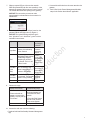
7. When prompted (Figure 12) enter the network
SSID and password (both are case sensitive) of the
network the gateway will connect to. Push “Connect.”
The mobile device will start pairing to the gateway.
NOTICE: The connection process can take
approximately 2 minutes before the connection is
established.
SSID
Password
Figure 12
8. Do the steps in the table that follows based on the
gateway’s Mode LED light color (D, Figure 1).
NOTICE: The typical blinking sequence goes
from "light blue > red > dark blue > green" over an
estimated two minutes.
Light color Status If color does
not change in
2 minutes
Light Blue Gateway is broadcasting
its own network.
Press
“Continue”
and repeat
Steps 6 - 7.
Red
BASCOGATEWAY-XXXXX
broadcasting stopped;
attempting to connect to
the network. This is in "Wi-
Fi Direct" mode.
Confirm
correct SSID
and password
are entered.
Repeat steps
4 - 7.
Dark Blue
(slow
blink)
Wi-Fi is connected. The
device is attempting to
connect to the Internet.
Make sure
the network is
connected to
the Internet.
Dark Blue
(fast blink)
Over the Air (OTA) server
is connected. The firmware
update is being installed.
Wait for the
update to
complete.
Green Connected Do Step 9.
9. Return to the app.
Display on the screen Troubleshooting Steps
“Please wait while we
attempt to connect to the
gateway...this may take up
to 2 minutes.”
1. Make sure the mobile
device and gateway are
connected to the same
network.
2. Press the “Back” button
(top left corner) until the
home screen appears.
Home screen Do Step 10.
10. Instruct the end user to do the following:
• Download and install the Standby Generator Management
app.
• Connect their mobile device to the same network as the
gateway.
11. Do the Set Up the Power Management Modules
steps in the section that follows if applicable.
Not for
Reproduction

10 BRIGGSandSTRATTON.COM
Set up the Power
Management Modules
This section explains how to connect the Power Management
Module to the gateway. Follow these steps after connecting the
gateway to a Wi-Fi network.
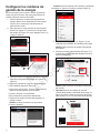
1. Open your app. Your power management device
shows up as available. In this example (Figure 13) it is
showing that a 12kW generator is available.
2. To add a load, push the upper right menu (A, Figure
13) and choose “Module Setup” (B, Figure 14) then
“Add New” (C) and then “Continue.”
A
Figure 13
CB
Figure 14
3. Push the Network Configuration button on all of the
power management devices (G, Figure 2 / B, Figure
3).
4. Return to the app and do the steps that follow:
• Push “Identify Device" (Figure 15).”
• Wait for the network light (L, Figure 2) on the Power
Management device to blink (amber in color).
• Push “OK” in the app
• Choose the previously identified device.
• Fill out the “Device Name” and “Nominal Voltage”
fields.
NOTICE: The remaining fields are optional.
• Push “Save.”
Figure 15
NOTICE:
After pairing multiple modules, the app screen will
resemble the image that follows (Figure 16):
Figure 16
5. Push the “Rearrange” icon (A, Figure 17) to arrange
load shed priorities.
NOTICE: The “Rearrange Priorities” screen should
appear.
6. Push and drag each item (B, Figure 17) to the desired
priority location. Save when completed (C).
.
Figure 17
A
C
B
NOTICE: The “Module Set-up” screen should appear.
7. Optional: To view “generator status and load status”
color codes (A, Figure 18), press the back button (B)
then press (i) button (C) near the right-side menu.
B
C
A
Figure 18
NOTICE: The generator and load statuses will
display on the “Home” and the “Module Set-Up”
screens.
Not for
Reproduction

11
Wireless Gateway Module
LED Indicators
Mode LED
• Cyan (light blue) – Wi-Fi Direct Mode
• Red – Cannot connect to the network access point
• Dark Blue –
Slow blink: Connected to the network access point
Fast blink: Device upgrade is in process
• Green – Connected to the InfoHub™ Cloud
WiFi LED
• On: Connected to the device update cloud
• Off: Not connected to the device update cloud
Please visit our website www.briggsandstratton.com for more
information and instructions regarding the
wireless gateway
module
.
Registration and Activation
Access to the InfoHub™ user portal requires purchase of a
subscription. You must register and activate the InfoHub system
on-line at www.infohubsp.com. User guides and instructional
videos are available at this site.
You will be required to read and comply with the InfoHub™
Subscription Service Agreement prior to activation of the monthly
subscription, and the Terms of Use and Privacy Policy prior to
accessing the InfoHub™ portal.
Visit www.briggsinfohub.com to preview those policies.
For registration and activation support, call the InfoHub™ support
team at 1-833-463-6482.
Prior to installation, record the module S/N in the spaces below.
This information is required to correctly assign the module to the
equipment in the user portal.
Amplify™ Gateway
S/N:
Equipment
Brand:
Equipment Type:
Model Number:
Serial Number
Minimum System Requirements
- User Portal
Supported Browsers and Versions
• Chrome - Version 59.0+
• Firefox - Version 54.0+
• Safari - Version 10.0+
• IE - Version 11.0+
• Edge - Version 15.0+
Minimum Display Resolution
• 1280 x 720
Computer Requirements
• Intel® Core™ i3 or equivalent
• 4GB of RAM
• Internet access
Special Settings
• Pop-ups are required for reporting.
• URL used for iFrame tool must support iFrames.
Not for
Reproduction

12 BRIGGSandSTRATTON.COM
Not for
Reproduction

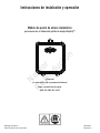
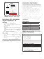
Módulo de puerta de enlace inalámbrico
para su uso con el sistema de gestión de energía Amplify™
Instrucciones de instalación y operación
¿Preguntas?
¡La ayuda está a solo un momento de distancia!
Llame a nuestra línea de ayuda:
(800) 732-2989 M-F 8-5 CT
© Briggs & Stratton
Todos los derechos reservados. 80079547
Revisión C
Not for
Reproduction

2 BRIGGSandSTRATTON.COM
Conserve estas instrucciones
Instrucciones de seguridad
importantes
GUARDE ESTAS INSTRUCCIONES - Este manual
contiene instrucciones importantes que deben seguirse
durante la instalación y el mantenimiento del generador y
las baterías.
Símbolos de seguridad y significados
El símbolo de alerta de seguridad indica un
posible riesgo para su integridad física. Una palabra
de señalización (PELIGRO, ADVERTENCIA o
PRECAUCIÓN) se utiliza con el símbolo de alerta para
designar un grado o nivel de gravedad del peligro. Se
puede usar un símbolo de peligro para representar el tipo
de riesgo. La palabra de señalización AVISO se utiliza
para abordar las prácticas no relacionadas con lesiones
corporales.
PELIGRO
indica un riesgo que, si no se evita,
ocasionará la muerte o lesiones graves.
ADVERTENCIA
indica un riesgo que, si no se evita,
podría ocasionar la muerte o lesiones graves.
PRECAUCIÓN
indica un riesgo que, si no se evita,
podría ocasionar lesiones leves o moderadas.
AVISO
hace referencia a las prácticas no relacionadas
con las lesiones personales
El fabricante no puede anticipar todas las circunstancias
que puedan suponer un peligro. Las advertencias de este
manual, así como las etiquetas y calcomanías que se
han fijado a la unidad, no son, por lo tanto, exhaustivas.
Si utiliza un procedimiento, método de trabajo o
técnica de operación que el fabricante no recomiende
específicamente, debe asegurarse de que sea seguro
para usted y para los demás. También debe asegurarse
de que el procedimiento, método de trabajo o técnica
operativa que elija no haga que el sistema generador sea
inseguro.
AVISO El tratamiento inadecuado del equipo podría dañarlo y
acortar su vida útil.
• Utilice el equipo solo para los usos previstos.
• Si tiene dudas sobre el uso previsto, pregunte al distribuidor o
póngase en contacto con Briggs & Stratton.
• NO exponga el equipo a humedad excesiva, polvo, suciedad o
vapores corrosivos.
• Esté alerta en todo momento mientras utiliza este equipo.
Nunca utilice el equipo si tiene cansancio físico o mental.
• Si los dispositivos conectados se sobrecalientan, apáguelos y
desconecte su disyuntor/fusible.
Lea el manualDescarga eléctrica
ADVERTENCIA Peligro de descarga. La instalación de
cables de bajo y alto voltaje en el mismo conducto
podría provocar la muerte, lesiones graves y/o daños
materiales.
• No opere un cable de voltaje bajo y alto en el mismo
conducto a menos que la clasificación del aislamiento en
TODOS los cables sea de 600 V. Consulte NEC para más
información.
ADVERTENCIA Si no se conecta el equipo a tierra de forma
adecuada, se puede producir una electrocución que
cause la muerte o lesiones graves.
• No toque los cables pelados.
• No utilice equipos con cables desgastados, deshilachados,
desnudos o dañados de alguna manera.
• No manipule los cables eléctricos mientras esté parado
en el agua, si está descalzo o si tiene las manos o los pies
mojados.
• Si tiene que trabajar cerca de una unidad mientras está en
operación, colóquese sobre una superficie seca y aislada para
reducir el riesgo de descarga eléctrica.
• No permita que personas no cualificadas o niños operen o
reparen el equipo.
• En caso de accidente causado por una descarga eléctrica,
desconecte inmediatamente todas las fuentes de energía
eléctrica y póngase en contacto con las autoridades locales.
Evite el contacto directo con la víctima.
ADVERTENCIA El equipo contiene alto voltaje que podría
causar electrocución con resultado de muerte o
lesiones graves.
• A pesar del diseño seguro del sistema, la operación de este
equipo de forma imprudente, descuidar su mantenimiento
o ser poco cuidadoso podría provocar la muerte o lesiones
graves.
ADVERTENCIA
Este producto contiene plomo y
compuestos de plomo, conocidos por el estado de
California por causar defectos de nacimiento u otros
daños reproductivos. Lávese las manos luego de
manipular este producto. Cáncer y daños reproductivos
- www.P65Warnings.ca.gov
Not for
Reproduction

3
AVISO Sección 15 de las FCC Información para el usuario
De acuerdo con la parte 15.21 de las normas de la FCC, se
le advierte que los cambios o modificaciones no aprobados
expresamente por Briggs and Stratton podrían anular su
autoridad para operar el dispositivo.
Este dispositivo cumple con el artículo 15 de las reglas FCC.
La operación está sujeta a las siguientes dos condiciones:
(1) Este dispositivo puede no causar interferencia peligrosa,
y (2) este dispositivo debe aceptar cualquier interferencia
recibida, lo que incluye a la interferencia que pudiere causar
una operación no deseada.
Este equipo fue probado y se determinó que cumple con
los límites para un dispositivo digital de Clase B, de acuerdo
con la Sección 15 de las Reglas FCC. Estos límites fueron
diseñados para brindar una protección razonable contra
la interferencia peligrosa en una instalación residencial.
Este equipo genera, usa y puede irradiar energía de
radiofrecuencia y, si no se instala y usa de acuerdo con las
instrucciones, podría ocasionar la interferencia peligrosa de
las radiocomunicaciones. Sin embargo, no se garantiza que
la interferencia no ocurra en una instalación particular. Se
alienta al usuario a que, en caso de que el equipo provoque
una interferencia peligrosa a la recepción de radio o televisión
(lo que puede determinarse al apagar y encender el equipo),
trate de corregir dicha interferencia al tomar una o más de las
siguientes medidas:
—Reorientar o reubicar la antena receptora.
—Aumentar la separación entre el equipo y el receptor.
—Conectar el equipo a un tomacorriente en un circuito que no
sea al cual el receptor está conectado.
—Consulte con el proveedor o un técnico experimentado en
radio/TV para obtener ayuda.
AVISO IC Información para el usuario
Este dispositivo cumple con los RSS exentos de licencia de
Industry Canadá. La operación está sujeta a las siguientes
dos condiciones:
(1) Este dispositivo no puede causar interferencias; y
(2) Este dispositivo debe aceptar cualquier interferencia,
incluidas las que puedan causar una operación no deseada
del dispositivo.
AVISO Declaración de exposición a la radiación RF de la FCC
para el usuario
Este equipo cumple con los límites de exposición a
la radiación de la FCC establecidos para un entorno
no controlado. Los usuarios finales deben seguir las
instrucciones de operación específicas para cumplir la
normativa de exposición a RF. Este dispositivo cumple con los
límites de exposición como se demuestra en un análisis de
exposición a RF. El dispositivo se debe instalar de forma que
se mantenga una distancia mínima de separación de 20 cm
entre el dispositivo y todas las personas en todo momento.
Información general
Descripción del equipo
Este producto está destinado únicamente a ser utilizado como
fuente de control inalámbrico del sistema del generador para
el propietario. Permite establecer las prioridades de las cargas
asignadas, como la calefacción, los sistemas de refrigeración
y los sistemas de comunicación que son controlados por el
generador. También proporciona información sobre el estado
del generador a la nube InfoHub™.
Dónde encontrarnos
Nunca tendrá que buscar mucho para encontrar soporte y
servicio para su generador. Consulte las Páginas Amarillas.
Hay muchos agentes de servicio autorizados en todo el
mundo que ofrecen un servicio de calidad. También puede
ponerse en contacto con el Servicio Técnico por teléfono en
el
800-732-2989 entre las 8:00 AM y las 5:00 PM hora central
o hacer clic en el localizador de distribuidores en www.
briggsandstratton.com, que proporciona una lista de
distribuidores autorizados.
Especificaciones del producto
Voltaje nominal .........................................................12V DC
Rango de funcionamiento normal -20 °F (-28,8 °C) a 104 °F (40 °C)
Peso 0.81 lbs. (0,37 kg)
*Este dispositivo está catalogado por UL (Underwriters Laboratories).
Complete la información que aparece a continuación y guarde
su recibo para ayudar a la identificación de la unidad en futuras
compras.
Número de modelo:
___________________________
Revisión
_______________
Número de serie:
__________________________
Fecha de la compra
_______________
Antes de la instalación
Solo los profesionales de la electricidad con licencia vigente
deben intentar las instalaciones de los módulos inalámbricos.
Las instalaciones deben cumplir estrictamente con todos
los códigos, normas de la industria, leyes y reglamentos
aplicables.
En algunas zonas puede necesitar permisos eléctricos para
instalar módulos inalámbricos. El instalador debe comprobar
los códigos locales y obtener los permisos necesarios antes
de instalar el módulo.
La garantía del módulo inalámbrico de la puerta de enlace es
NULA a menos que el módulo sea instalado por profesionales
eléctricos autorizados.
Responsabilidades del instalador
• Lea y observe las instrucciones de seguridad.
• Lea y siga las instrucciones de este Manual de
instalación y operaciones.
• La instalación debe cumplir estrictamente con todos
los códigos, estándares de la industria, leyes y
regulaciones aplicables.
• Deje suficiente espacio en todos los lados del módulo
inalámbrico para el mantenimiento y el servicio.
Not for
Reproduction

4 BRIGGSandSTRATTON.COM
A • Indicador LED de potencia
B • Botón de Configuración de WiFi
C • Botón de Configuración del dispositivo
D • Modo LED
E • Indicador LED de WiFi
F • Indicador LED de RS-485
G • Indicador LED del dispositivo
H • LED indicador de la CPU
J • Botón de reinicio
K • Bloque de terminales de entrada (conexiones de campo)
L • Puerto de servicio (serie)
El módulo inalámbrico se puede instalar donde sea conveniente y haya una buena señal inalámbrica, ya sea en un lugar interior
o exterior. El
módulo de la puerta de enlace inalámbrica
debe ser accesible para el servicio. Analice con el propietario las
sugerencias o cambios en el diseño antes de comenzar el proceso de instalación del sistema.
VIN+ D+ D- GND
Power
WiFi
Mode
RS-485
Device
CPU
WiFi
Config
Device
Config E
D
F
G
H
L
A B C
K
J
Figura 1
Not for
Reproduction

5
A • L1 IN
B • L2/N IN
C • 230VAC N
D • Tierra
E • L1 OUT
F • L2/N OUT
G • Botón de configuración de la red (Join)
H • LED de potencia
J • LED de relé
K • LED de averías
L • LED de la red
A • 24 VAC Entrada de energía
B • Botón de configuración de la red
(Join)
C • Salida de la carga #2
D • Salida de la carga #1
E • LED de averías
F • LED de red
G • LED de potencia
H • Salida 2 LED
J • Salida 1 LED
G
B A EF C
L2/N OUT L1 OUTL2/N IN L1 IN 230VAC N 230VAC N
D
J K L
H
Figura 2
A
CD
B
EG
HJ
F
Figura 3
Not for
Reproduction

6 BRIGGSandSTRATTON.COM
Instalación
Se recomienda utilizar un cable de par trenzado doble de 18 AWG
para conectar el
módulo de la puerta de enlace inalámbrica
al
generador. Este cable está disponible en Briggs and Stratton. Para
más información, visite nuestro sitio web en
www.briggsandstratton.
com
.
Instrucciones de montaje
Los módulos de gestión de la energía están contenidos en una caja
NEMA tipo 4. Los componentes del módulo de la puerta de enlace
inalámbrica están contenidos en una caja NEMA Tipo 3R que es
adecuada para uso en interiores/exteriores. Las instrucciones para
el montaje del gabinete incluyen:
• Instalar el gabinete sobre una estructura de soporte firme y
resistente.
• El gabinete debe ser accesible para el servicio.
• NUNCA instale el dispositivo donde cualquier sustancia
corrosiva pueda gotear sobre el gabinete.
• Proteja el aparato en todo momento contra la humedad
excesiva, el polvo, la suciedad, las pelusas, la arenilla de
construcción y los vapores corrosivos.
• Instalar un gabinete para maximizar el rendimiento inalámbrico.
Evite montar el gabinete en espacios metálicos reducidos.
Cuando sea posible, monte el gabinete en un área abierta.
• El gabinete debe montarse en posición vertical de modo que
el ojal (A, Figura 4) esté en la parte inferior para evitar que el
agua entre en la caja.
Figura 4
A
Desconecte la corriente
Antes de realizar cualquier instalación, mantenimiento o
servicio en el generador, realice SIEMPRE los siguientes
pasos:
1. Ponga el sistema del generador en OFF (APAGADO).
2. Ponga el disyuntor de circuito del generador en OFF
(APAGADO).
3. Retire el fusible del generador principal.
4. El voltaje de la red está presente en el panel
de control del generador. Retire los fusibles del
interruptor de transferencia para desconectar la energía
antes de reparar el panel de control.
5. Desconecte el cable negativo de la batería del terminal
negativo de la batería, indicado por NEGATIVO, NEG o
(-).
Conecte los cables
Retire la cubierta (A, Figura 5) del
módulo de la puerta de enlace
inalámbrica
aflojando los tornillos (B) NO retire el ojal de goma (C)
del orificio de la parte inferior de la caja.
Figura 5
C
A
B
B
B
Modelos PowerProtect 17 kW, 20 kW y 26 kW (Figura 6):
Conecte las entradas del módulo de la puerta de enlace
inalámbrica (A, Figura 6) a los bloques de terminales
de
cableado de campo “WiFi” del generador (B). Las
conexiones
del bloque de terminales del módulo de puerta de enlace
inalámbrica
y las conexiones del bloque de terminales del
generador deben apretarse a 0,5 Nm (4,4 pulg-lb).
Figura 6
VIN+ D+ D- GND
9
11
12
13
15
16
(B)
+12V
(A)
GND
+12V
(B)
(A)
GND
W
I
F
I
C
E
L
L
U
L
A
R
10
14
VIN+ D+ D- GND
9
11
12
13
15
16
GND
+12V
(B)
(A)
GND
W
I
F
I
C
E
L
L
U
L
A
R
10
14
VIN+ D+ D- GND
9
11
12
13
15
16
GND
+12V
(B)
(A)
GND
W
I
F
I
C
E
L
L
U
L
A
R
10
14
FortressPower Protect 17, 20, 26kW Power Protect 12kW Only
AB
C
D
E
F
AB
C
D
E
F
AB
C
DE
F
1. Conecte el cable rojo (C, Figura 6) al terminal “WiFi
VIN+ (+12V)” del generador y al terminal “VIN(+)” del
módulo de la puerta de enlace inalámbrica.
2. Conecte el cable negro (F, Figura 6) al terminal
“WiFi GND” del generador y al terminal “GND” del
módulo de la puerta de enlace inalámbrica.
3. Conecte el cable blanco (D, Figura 6) al terminal “WiFi
D+” del generador y al terminal “D+” del módulo de la
puerta de enlace inalámbrica.
4. Conecte el cable naranja (E, Figura 6) al terminal “WiFi
D-” del generador y al terminal “D-” del módulo de la
puerta de enlace inalámbrica.
Not for
Reproduction

7
5. Conecte el cable de protección (si está instalado)
al terminal GND del módulo de la puerta de enlace
inalámbrica o al “WiFi GND” del generador, NO a
ambos.
Modelos PowerProtect™ 12 kW (Figura 7):
Conecte las entradas del módulo de la puerta de enlace
inalámbrica (A, Figura 7) a los bloques de terminales de
cableado de campo “WiFi”
del generador (B). Las
conexiones
del bloque de terminales del módulo de puerta de enlace
inalámbrica
y las conexiones del bloque de terminales del
generador deben apretarse a 0,5 Nm (4,4 pulg-lb).
Figura 7
VIN+ D+ D- GND
9
11
12
13
15
16
(B)
+12V
(A)
GND
+12V
(B)
(A)
GND
W
I
F
I
C
E
L
L
U
L
A
R
10
14
VIN+ D+ D- GND
9
11
12
13
15
16
GND
+12V
(B)
(A)
GND
W
I
F
I
C
E
L
L
U
L
A
R
10
14
VIN+ D+ D- GND
9
11
12
13
15
16
GND
+12V
(B)
(A)
GND
W
I
F
I
C
E
L
L
U
L
A
R
10
14
FortressPower Protect 17, 20, 26kW Power Protect 12kW Only
AB
C
D
E
F
AB
C
D
E
F
AB
C
DE
F
1. Conecte el cable rojo (C, Figura 7) al terminal “WiFi
VIN+ (+12V)” del generador y al terminal “VIN(+)” del
módulo de la puerta de enlace inalámbrica.
2. Conecte el cable negro (F, Figura 7) al
terminal “WiFi GND” del generador y al terminal “GND”
del módulo de la puerta de enlace inalámbrica.
3. Conecte el cable blanco (D, Figura 7) al terminal “WiFi
D+” del generador y al terminal “D+” del módulo de la
puerta de enlace inalámbrica.
4. Conecte el cable naranja (E, Figura 7) al terminal “WiFi
D-” del generador y al terminal “D-” del módulo de la
puerta de enlace inalámbrica.
5. Conecte el cable de protección (si está instalado)
al terminal GND del módulo de la puerta de enlace
inalámbrica o al “WiFi GND” del generador, NO a
ambos.
Los modelos Fortress y Briggs & Stratton®, en su caso
(Figura 8):
Conecte las entradas del módulo de la puerta de enlace
inalámbrico (A, Figura 8) a los bloques de terminales de
cableado de campo “WiFi”
del generador (B). Las
conexiones
del bloque de terminales del módulo de puerta de enlace
inalámbrica
y las conexiones del bloque de terminales del
generador deben apretarse a 0,5 Nm (4,4 pulg-lb).
Figura 8
VIN+ D+ D- GND
9
11
12
13
15
16
(B)
+12V
(A)
GND
+12V
(B)
(A)
GND
W
I
F
I
C
E
L
L
U
L
A
R
10
14
VIN+ D+ D- GND
9
11
12
13
15
16
GND
+12V
(B)
(A)
GND
W
I
F
I
C
E
L
L
U
L
A
R
10
14
VIN+ D+ D- GND
9
11
12
13
15
16
GND
+12V
(B)
(A)
GND
W
I
F
I
C
E
L
L
U
L
A
R
10
14
FortressPower Protect 17, 20, 26kW Power Protect 12kW Only
AB
C
D
E
F
AB
C
D
E
F
AB
C
DE
F
1. Conecte el cable rojo (C, Figura 8) al terminal “WiFi
+12V” del generador y al terminal “VIN(+)” del módulo
de la puerta de enlace inalámbrico.
2. Conecte el cable negro (F, Figura 8) al
terminal “WiFi GND” del generador y al terminal “GND”
del módulo de la puerta de enlace inalámbrico.
3. Conecte el cable blanco (D, Figura 8) al terminal “WiFi
A+” del generador y al terminal “D+” del módulo de la
puerta de enlace inalámbrico.
4. Conecte el cable naranja (E, Figura 8) al terminal “WiFi
B” del generador y al terminal “D-” del módulo de la
puerta de enlace inalámbrico.
5. Conecte el cable de protección (si está instalado)
al terminal GND del módulo de la puerta de enlace
inalámbrica o al “WiFi GND” del generador, NO a
ambos.
Cierre el generador e instale los fusibles
Después de realizar cualquier instalación, mantenimiento
o servicio en el generador, realice SIEMPRE los siguientes
pasos:
1. Utilice ataduras para organizar los cables y asegurar el
exceso de longitud de los mismos.
2. Instale todos los componentes que se quitaron.
3. Conecte el cable negativo de la batería al terminal
negativo de la batería (indicado por NEGATIVO, NEG,
o (-).
4. Instale los fusibles en el interruptor de transferencia.
5. Instale el fusible del generador.
Not for
Reproduction

8 BRIGGSandSTRATTON.COM
6. Ponga el disyuntor de circuito del generador en
ENCENDIDO.
7. Coloque el interruptor del sistema del generador en la
posición AUTO/Standby.
El módulo de la puerta de enlace inalámbrica debería
encenderse automáticamente. Compruebe que el LED
POWER (A, Figura 1) está encendido.
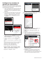
Configure la puerta de enlace
con el sistema de gestión de la
energía
Utilice este procedimiento para conectar el módulo de puerta
de enlace inalámbrico InfoHub™ (también denominado “puerta
de enlace”) al sistema de gestión de energía Amplify™ para la
conexión inalámbrica.
Antes de comenzar:
• Coloque
la puerta de enlace
dentro del alcance del sistema
de administración de energía. El alcance exacto variará
en función del entorno de la vivienda y lo determinarán
los técnicos instaladores (véase la sección Directrices de
montaje).
• Asegúrese de que la luz verde de alimentación de la puerta
de enlace (A, figura 1) está encendida y el MODO LED (D,
figura 1) parpadea en azul claro.
1. Conecte el dispositivo móvil a la red WiFi que se
emparejará con la puerta de enlace.
2. Descargue e instale la aplicación Generador de
energía de emergencia en un dispositivo móvil. Use
Google Play Storepara Android o Apple Play Storepara
iOS.
AVISO: Tras la instalación, aparecerá la pantalla
“COMENZAR” (Figura 9).
3. Presione lo siguiente en la aplicación:
• “Amplificar la gestión de la energía” (A, Figura 9).
• “Intro” (B)
• Menú superior derecho (C)
• “WiFi” (D)
D
A
C
B
Figura 9
AVISO: El icono a la izquierda de “WiFi” (D) cambiará si
la puerta de enlace ya está conectada a una red
4. Ponga la puerta de enlace en “Modo WiFi Directo”
presionando y manteniendo pulsado el botón
Configuración WiFi (B, Figura 1) en la placa de la
puerta de enlace durante 5 segundos. El MODO LED
(D, Figura 1) parpadeará.
5. Siga los pasos de la tabla siguiente en función del color
de la luz LED demodo de la puerta de enlace (D, Figura
1).
Si el MODO LED (D,
Figura 1) está:
Haga lo siguiente en la puerta
de enlace:
Azul claro Pulse SÍ (A, Figura 10)
Azul oscuro
• Pulse el botón de reinicio
(J, Figura 1).
• Mantenga pulsado
el botón WiFi Config
(B, Figura 1) durante
5 segundos.
• Repita la operación
hasta que el LED (D,
Figura 1) se ilumine de
color azul claro.
Rojo
Verde
AVISO: El azul oscuro y el verde indican que la puerta
de enlace ya está conectada a una red.
Not for
Reproduction
La page est en cours de chargement...
La page est en cours de chargement...
La page est en cours de chargement...
La page est en cours de chargement...
La page est en cours de chargement...
La page est en cours de chargement...
La page est en cours de chargement...
La page est en cours de chargement...
La page est en cours de chargement...
La page est en cours de chargement...
La page est en cours de chargement...
La page est en cours de chargement...
La page est en cours de chargement...
La page est en cours de chargement...
La page est en cours de chargement...
La page est en cours de chargement...
-
 1
1
-
 2
2
-
 3
3
-
 4
4
-
 5
5
-
 6
6
-
 7
7
-
 8
8
-
 9
9
-
 10
10
-
 11
11
-
 12
12
-
 13
13
-
 14
14
-
 15
15
-
 16
16
-
 17
17
-
 18
18
-
 19
19
-
 20
20
-
 21
21
-
 22
22
-
 23
23
-
 24
24
-
 25
25
-
 26
26
-
 27
27
-
 28
28
-
 29
29
-
 30
30
-
 31
31
-
 32
32
-
 33
33
-
 34
34
-
 35
35
-
 36
36


Simplicity Wireless Gateway Guide d'installation
- Taper
- Guide d'installation
dans d''autres langues
Documents connexes
Autres documents
-
Eurotech ReliaGATE 10-20 Le manuel du propriétaire
-
Eurotech ReliaGATE 20-25 Le manuel du propriétaire
-
Miller CONTINUUM 500 Le manuel du propriétaire
-
-
-
-
-
Sinope GT130 Guide d'installation