NAD S200 Le manuel du propriétaire
- Catégorie
- Haut-parleurs de la barre de son
- Taper
- Le manuel du propriétaire

S200
Stereo Power Amplifier
Owner’s Manual
GB
Manuel d’Installation
F
Bedienungsanleitung
D
Manual del Usuario
E
Manuale delle Istruzioni
I
Manual do Proprietário
P
Bruksanvisning
S

Warning: To reduce the risk of fire or electric shock, do not
expose this unit to rain or moisture.
The lightning flash with an arrowhead symbol within an equilateral
triangle, is intended to alert the user to the presence of uninsulated
“dangerous voltage” within the product’s enclosure that may be of
sufficient magnitude to constitute a risk of electric shock to persons.
The exclamation point within an equilateral triangle is intended to
alert the user to the presence of important operating and
maintenance (servicing) instructions in the literature accompanying
the product.
Do not place this unit on an unstable cart, stand or tripod, bracket
or table. The unit may fall, causing serious injury to a child or adult
and serious damage to the unit. Use only with a cart, stand, tripod,
bracket or table recommended by the manufacturer or sold with
the unit. Any mounting of the device on a wall or ceiling should
follow the manufacturer’s instructions and should use a mounting
accessory recommended by the manufacturer.
An appliance and cart combination should be moved with care.
Quick stops, excessive force and uneven surfaces may cause the
appliance and cart combination to overturn.
Read and follow all the safety and operating instructions before
connecting or using this unit. Retain this notice and the owner’s
manual for future reference.
All warnings on the unit and in its operating instructions should be
adhered to.
Do not use this unit near water; for example, near a bath tub,
washbowl, kitchen sink, laundry tub, in a wet basement or near a
swimming pool.
The unit should be installed so that its location or position does not
interfere with its proper ventilation. For example, it should not be
situated on a bed, sofa, rug or similar surface that may block the
ventilation openings; or placed in a built-in installation, such as a
bookcase or cabinet, that may impede the flow of air through its
ventilation openings.
The unit should be situated from heat sources such as radiators,
heat registers, stoves or other devices (including amplifiers) that
produce heat.
The unit should be connected to a power supply outlet only of the
voltage and frequency marked on its rear panel.
The power supply cord should be routed so that it is not likely to be
walked on or pinched, especially near the plug, convenience
receptacles, or where the cord exits from the unit.
Unplug the unit from the wall outlet before cleaning. Never use
benzine, thinner or other solvents for cleaning. Use only a soft
damp cloth.
The power supply cord of the unit should be unplugged from the
wall outlet when it is to be unused for a long period of time.
Care should be taken so that objects do not fall, and liquids are not
spilled into the enclosure through any openings.
This unit should be serviced by qualified service personnel when:
A. The power cord or the plug has been damaged; or
B. Objects have fallen, or liquid has been spilled into the unit; or
C. The unit has been exposed to rain or liquids of any kind; or
D. The unit does not appear to operate normally or exhibits a
marked change in performance; or
E. The device has been dropped or the enclosure damaged.
DO NOT ATTEMPT SERVICING OF THIS UNIT
YOURSELF. REFER SERVICING TO QUALIFIED
SERVICE PERSONNEL
Upon completion of any servicing or repairs, request the service
shop’s assurance that only Factory Authorized Replacement Parts
with the same characteristics as the original parts have been used,
and that the routine safety checks have been performed to
guarantee that the equipment is in safe operating condition.
REPLACEMENT WITH UNAUTHORIZED PARTS MAY RESULT IN FIRE,
ELECTRIC SHOCK OR OTHER HAZARDS.
ATTENTION
POUR ÉVITER LES CHOC ELECTRIQUES, INTRODUIRE LA
LAME LA PLUS LARGE DE LA FICHE DANS LA BORNE
CORRESPONDANTE DE LA PRISE ET POUSSER JUSQU’AU
FOND.
CAUTION
TO PREVENT ELECTRIC SHOCK, MATCH WIDE BLADE OF
PLUG TO WIDE SLOT FULLY INSERT.
If an indoor antenna is used (either built into the set or installed
separately), never allow any part of the antenna to touch the metal
parts of other electrical appliances such as a lamp, TV set etc.
CAUTION
POWER LINES
Any outdoor antenna must be located away from all power lines.
OUTDOOR ANTENNA GROUNDING
If an outside antenna is connected to your tuner or tuner-
preamplifier, be sure the antenna system is grounded so as to
provide some protection against voltage surges and built-up static
charges. Article 810 of the National Electrical Code, ANSI/NFPA No.
70-1984, provides information with respect to proper grounding of
the mast and supporting structure, grounding of the lead-in wire to
an antenna discharge unit, size of grounding conductors, location of
antenna discharge unit, connection to grounding electrodes and
requirements for the grounding electrode.
a. Use No. 10 AWG (5.3mm2) copper, No. 8 AWG (8.4mm2)
aluminium, No. 17 AWG (1.0mm2) copper-clad steel or bronze
wire, or larger, as a ground wire.
b. Secure antenna lead-in and ground wires to house with stand-off
insulators spaced from 4-6 feet (1.22 - 1.83 m) apart.
c. Mount antenna discharge unit as close as possible to where lead-
in enters house.
d. Use jumper wire not smaller than No.6 AWG (13.3mm2) copper,
or the equivalent, when a separate antenna-grounding electrode
is used. see NEC Section 810-21 (j).
EXAMPLE OF ANTENNA GROUNDING AS PER NATIONAL ELECTRICAL
CODE INSTRUCTIONS CONTAINED IN ARTICLE 810 - RADIO AND
TELEVISION EQUIPMENT.
NOTE TO CATV SYSTEM INSTALLER: This reminder is
provided to call the CATV system installer’s attention to
Article 820-40 of the National Electrical Code that provides
guidelines for proper grounding and, in particular, specifies
that the ground cable ground shall be connected to the
grounding system of the building, as close to the point of
cable entry as practical.
CAUTION
RISK OF ELECTRIC
SHOCK DO NOT OPEN
ATTENTION:
RISQUE DE CHOC ELECTRIQUE
NE PAS OUVRIR
CAUTION: TO REDUCE THE RISK OF ELECTRIC
SHOCK, DO NOT REMOVE COVER (OR BACK). NO
USER SERVICEABLE PARTS INSIDE. REFER SERVICING
TO QUALIFIED SERVICE PERSONNEL.
IMPORTANT SAFETY INSTRUCTIONS
2

3
FRONT PANEL CONTROLS
REAR PANEL CONNECTIONS
FIGURE 1
©1998 NAD S200©1998 NAD S200

GB
4
NAD S200 Stereo Power Amplifier
NOTES ON INSTALLATION
This unit may be installed on any level surface that is strong enough
to support its weight. Since its power transformer generates a
significant magnetic hum field, a turntable (especially one with a
moving-coil pick-up cartridge) or a TV should not be located adjacent
to the amplifier or directly above it.
The heat-sink fins make it awkward to lift the S200 by grasping the
left and right sides. You may find it more practical to place your
hands under the front and rear panels. Much of the amplifier’s
weight is near the front panel.
CAUTION: The amplifier’s weight must always rest on its bottom feet.
Never put the amplifier down on its rear panel, with its front panel
facing up. Doing so risks damage to the input/output connectors.
The amplifier generates a moderate amount of heat, requiring
internal ventilation. Do not permit the air outlet grille on the top
cover to be obstructed by papers or articles of clothing. If you want
to locate the amplifier on a carpeted floor, place a board under the
amplifier in order to prevent it from sinking into the carpet, blocking
the air inlets on its bottom.
CAUTION: To prevent a fire or shock hazard, do not permit liquid or
moisture to enter the amplifier. If liquid is accidentally spilled on it,
immediately shut off the power and unplug the AC Mains cable
from the wall outlet.
Do not open the amplifier or attempt to modify or repair it
yourself. Refer all servicing to a qualified technician.
REAR PANEL CONNECTIONS
1. IEC AC MAINS (POWER) INPUT
The NAD S200 comes supplied with a separate AC Mains cable.
Before connecting the cable to a live wall socket ensure that it is
firmly connected to the S200’s AC Mains input socket first. Always
disconnect the AC Mains cable plug from the live wall socket first,
before disconnecting the cable from the S200 Mains input socket.
Plug the AC Mains cable into a live wall socket. If you must use an
extension cord, select a heavy-duty cord of the type used for large
electrical appliances.
Do not connect the amplifier’s Mains cable to the accessory AC outlets
on a preamplifier. Such convenience outlets are not designed to supply
the high power levels, up to 800 watts, that the S200 requires. If you
wish to switch your entire audio system on and off at once, plug both
the S200 and your preamplifier into a “power strip” containing several
grounded AC outlets and a high-current on/off switch.
Voltage conversion. A notice printed on the rear indicates the AC
power-line voltage that the amplifier requires. However, every model
S200 amplifier has a “universal” power supply that can be modified
easily for operation in other countries. If you wish to transport your
S200 to a nation that employs a different power-line voltage, an
authorised NAD dealer or service agency can convert it for such use.
2. SPEAKERS
This amplifier is equipped with special high-current binding post
speaker terminals to handle the highest peak power levels that may
occur in the “bridged” mode or with low-impedance speakers. At
moments when the amplifier is producing maximum power, voltages
of nearly 100 V may be present on the speaker terminals, so the
terminals are protected by transparent plastic covers.
To connect loudspeaker cables, first switch off the amplifier’s power.
If you are connecting a pair of speakers for normal stereo operation,
be sure that the bridging switch is set to OFF (STEREO).
For best stereo imaging, the left and right speakers should be located
at equal distances from your chair. To minimise the effect of speaker
cables on the sound, locate the amplifier near the speakers and use
short cables to connect the speakers. If your preamplifier is located at
the opposite end of the room near your chair, you will need a long
cable to connect it to the power amplifier. All NAD preamplifiers have
the low output impedance required to drive long connecting cables.
Connect the wires from your left channel speaker to the (L+) and (L-)
terminals on the rear panel of the S200, and connect the wires from
the right channel speaker to the (R+) and (R-) terminals. In each
channel, the red terminal is the positive (+) output, and the black
terminal is the negative (-) or “ground” terminal.
Use heavy duty (16-gauge/2 sq.mm or thicker) wire, especially with 4
ohm loudspeakers. Bare wires can be connected directly to the
binding post terminals. For a longer lasting and more corrosion
resistant connection, you may purchase speaker cables with gold
plated connectors (pin connectors or spade lugs), or you can install
such connectors on the wires yourself. Connections to each binding
post may be made in several ways as follows. (See Figure 1.)
1. Pin connectors. A pin connector is a slim metal shaft that is crimped
or soldered onto the end of a wire. The threaded shaft of each
binding post contains an opening that accepts pin connectors up
to 3mm in diameter. Unscrew the plastic bushing on each terminal
to expose the hole in the metal shaft. Insert the pin connector
through the hole, and turn the bushing clockwise until it is tight.
2. Spade lugs. Unscrew the plastic bushing, insert the U-shaped spade
lug into the oblong gap and tighten the bushing down on it.
3. Bare wires. Separate the two conductors of the cord (if they appear
as a pair), and strip off a half-inch (1cm) of insulation from each. In
each conductor, twist together the exposed wire strands. Unscrew
the plastic bushings for + and -, insert the bare wire through the
hole in the metal shaft, and tighten the plastic bushing until it
grasps the wire securely. Check to be sure that no loose strand of
wire is touching the chassis or an adjacent terminal. Re-tighten the
bushing after a week or so to make sure that any play that may
have developed is eliminated.

CAUTION: Safety organisations recommend that the speaker
terminals of a very powerful amplifier should be covered. Potentially
dangerous voltages are present on these terminals when the
amplifier is producing maximum power. For your protection and in
order to comply with these regulations, we have chosen speaker
terminals of the very highest quality for the NAD S200. These
terminals are covered by plastic bushings which prevent the touching
of metal parts.
PHASING
Stereo speakers must operate “in phase” with each other to produce
a focused stereo image and to reinforce rather than cancel each
other’s output at low frequencies. An in-phase connection is assured
if the red (positive) terminal on the amplifier is connected to the red
(positive) terminal on the loudspeaker in each channel.
If your speakers are easily moved, their phasing can easily be checked.
Make the connections to both speakers, place the speakers face-to-
face only a few inches apart, play some music, and listen. Then swap
the connection of the two wires at the back of ONE of the speakers,
and listen again. The connection which produces the fullest, boomiest
bass output is the correct one. Connect the wires securely to the
speaker terminals, being careful not to leave any loose strands of wire
that might touch the wrong terminal and create a partial short-circuit
then move the speakers to their intended locations.
If the speakers cannot easily be set face-to-face, then phasing must
rely on the “polarity” of the connecting wires. The speaker terminals
on the amplifier are identified as red (+) and black (-) in each
channel. The terminals at the rear of the speakers are also marked
for polarity, either via red and black connectors or by labels: “+”,
“1”, or “8 ohms” for positive, “-”, “0”, or “G” for negative. The
red (+) terminal on the amplifier should be connected to the red
(positive) terminal of the speaker in each channel.
To facilitate this, the two conductors comprising the speaker wire in
each channel are different, either in the colour of the wire itself
(copper vs. silver) or in the presence of a small ridge or rib pattern on
the insulation of one conductor. Use this pattern to establish
consistent wiring to both speakers of a stereo pair. Thus if you
connect the copper coloured wire (or ribbed insulation) to the (+)
amplifier terminal in the Left channel, do the same in the Right
channel. At the other end of the wire, if you connect the copper
coloured wire (or the ribbed insulation) to the red or positive terminal
on the left channel speaker, do the same at the right channel speaker.
3. LEFT CHANNEL INPUTS
(BALANCED/UNBALANCED)
Before making or changing input connections to the amplifier, make
certain that the Power is Off.
The S200 amplifier is equipped with two input connectors for each
channel. The RCA phono jack is a conventional “unbalanced” input.
The three-hole XLR socket is a professional “balanced” input. You
may use either type of input, but not both.
If your preamplifier has only conventional outputs with RCA phono
jacks, connect an audio connecting cable from the left channel
output of the preamplifier to the left channel UNBALANCED input of
the S200. Set the BALANCE switch to UNBAL.
If your preamplifier has balanced XLR outputs, connect a three-
conductor cable from your left channel preamplifier output to the
left-channel XLR input on the S200, and set the BALANCE switch to
BAL. If your audio dealer does not have the appropriate cables,
purchase balanced “microphone” cables from a shop that sells
professional recording equipment. The end of the cable that has a
“male” XLR plug (with three metal pins) should be connected to the
S200 amplifier. The end of the cable that has a “female” XLR socket
(with three holes) should be connected to your preamplifier.
An XLR plug is “keyed” so that it fits into the socket only one way. If
there is a set-screw in the barrel of the plug, align it with the top of
the connector. Push the plug fully into the XLR socket until it latches
in place.
The three pins of an XLR type (“Cannon”) connector are numbered.
Pin 2 is the signal “hot” connection in the S200, Pin 2 is connected
directly to the center pin of the unbalanced RCA phono jack. Pin 3 is
the signal return (signal ground) connection. Pin 1 is the chassis earth
(ground), to which the shield of a balanced-wire cable is connected.
UNPLUGGING
The XLR socket has a latching feature that prevents the connector
from being pulled out by accident. Before disconnecting an input
cable, turn off the Power. Use one hand to press the latching tab
above the XLR socket while using the other hand to pull the XLR
plug out.
4. RIGHT CHANNEL INPUTS
(BALANCED/UNBALANCED)
Make connections to the right channel input in the same way that
you did for the left channel.
5. INPUT SELECT (BALANCED/UNBALANCED)
Set this switch to match your selection of input connector. Set to
UNBAL if you have connected a cable from your preamplifier to the
RCA phono input jacks. Set the switch to BAL if you are making
connections to the balanced XLR inputs.
Normally the choice of input connector is determined by the output
connectors on your preamplifier. If your preamplifier has balanced
outputs, use three-conductor cables equipped with XLR connectors.
If your preamplifier has only “unbalanced” connections with RCA
phono jacks, use the corresponding inputs on the S200.
GB
5

GB
6
THE BENEFITS OF BALANCED CONNECTIONS
With a conventional (unbalanced) connection, audio signal current
flows from the preamplifier to the power amplifier via the cable’s
centre conductor. To complete the circuit, audio signal current flows
back to the preamplifier ground via the cable’s outer conductor. The
outer conductor also serves as the cable’s shield.
When two audio components are connected together, power-supply
noise and “leakage” hum may also flow on the cable shields,
combining with the return audio current. The resulting distortion and
noise may depend on the orientation of AC power plugs in their
sockets. Designers of some audiophile cables combat this
contamination by leaving the shield unconnected at one end. Since
the shield is grounded at only one end, the performance of such a
cable may depend on the direction of its connection, i.e. whether the
shield is grounded at the preamplifier or at the power amplifier.
A three-wire balanced connection avoids all of these uncertainties.
The signal “hot” and return currents are both carried on inner
conductors. The separate cable shield, connected to the amplifier
chassis at both ends, protects the audio signal from all forms of
interference and power-supply noise. The advantage of this approach
is particularly evident with long connecting cables. Therefore, while
the S200 can provide excellent sound when used with any
preamplifier, the best (and most consistent) performance will be
obtained with a preamplifier that has balanced output wiring.
6. SOFT CLIPPING ON/OFF
When an amplifier is overdriven beyond its maximum power output
it normally produces “hard clipping” of the signal with harsh
distortion and power-supply buzz as the output transistors saturate.
The NAD Soft Clipping circuit gently limits the output waveform and
minimises audible distortion when the amplifier is overdriven. It
should be switched ON when playing music at very high levels that
might exceed the amplifier’s power capacity. For convenience it may
be left ON at all times.
7. BRIDGING ON (MONO) / OFF (STEREO)
This switch “bridges” the two channels together, forming a
monophonic amplifier with more than double the output power.
To convert to bridged operation, the following procedure should be
followed.
1. Switch Off the POWER.
NOTE: In the bridged mode the loudspeaker’s impedance is effectively
halved as “seen” by the amplifier. An 8 ohm load looks like 4
ohms, a 4 ohm load looks like 2 ohms, and a pair of 4 ohm
speakers operated in parallel will resemble a 1 ohm load. Driving
paralleled low-impedance speakers to high levels will cause the
amplifier to overheat and shut down, or may cause internal fuses
to blow in order to protect the amplifier. In bridged mode you must
connect only ONE loudspeaker per channel whose nominal
impedance is 8 ohms or higher.
2. Disconnect any signal cables from the input jacks. Decide whether
this amplifier will be driving the left or right speaker. Connect the
corresponding (left or right) signal cable from your preamplifier to
one of the L input jacks of this amplifier.
NOTE: In the bridged mode the amplifier is driven only through its L
(Left) input, even though it may be connected to the right speaker.
If another NAD S200 amplifier in bridged mode is used for the
second stereophonic channel, it also will be driven through its L
input, regardless of whether it is used to drive the left or right
loudspeaker.
3. Disconnect any wires from the speakers terminals. Select the wire
from the speaker that will be driven by this bridged amplifier.
Connect its “positive” conductor to the L+ terminal and its
“negative” conductor to the R+ terminal (i.e. the two red terminals).
Do NOT connect any wires to the black terminals (L- and R-).
CAUTION: In the bridged mode the speaker wires must be “floating”
with respect to the circuit ground. Do NOT connect the speaker
wires to anything that shares a common ground between stereo
channels (such as a speaker switch or an adapter for electrostatic
headphones), nor to anything which shares a common ground
with the amplifier’s inputs (such as a switching comparator or a
distortion analyzer).
4. After the preceding conditions have been satisfied, move the
BRIDGING switch to ON (MONO). Finally turn the Power ON.
5. To return the amplifier to normal stereo operation at a later date,
first turn off the power. Re-set the BRIDGING switch to OFF
(STEREO). Restore normal left and right input connections, and re-
connect loudspeaker wires to the speaker terminals as described
above under SPEAKERS.
FRONT PANEL CONTROLS
1. POWER ON/OFF
Press the Power button to turn on the amplifier. The blue LED glows
when the power is on and the amplifier is ready for use. Press the
Power button again to switch the amplifier off.
2. POWER INDICATOR (STATUS)
This blue LED lights up when the S200 is switched on, and indicates
the operating status of the amplifier as follows.
DARK: Power off. The Power switch may be off, the AC Mains cable
may be unplugged or not connected to a live wall outlet, or the
internal fuse may have blown.
BLUE: Power on. The amplifier is ready for use.
3. PROTECTION INDICATOR
This blue LED lights up when the Protection mode is engaged,
meaning that the loudspeakers have been disconnected by an
internal relay. This mode is activated briefly during turn-on and turn-
off, to protect the speakers from low frequency thumps. At other
times the Protection mode may be activated by severe overheating,
short-circuited speaker wiring, or an internal fault.

GB
7
If the blue LED indicator lights up continuously, switch the Power Off.
When the output stage cools, relays will automatically re-connect the
speakers, and normal operation can be resumed. In most cases a
very slight reduction in volume level will prevent further interruptions.
If the protection relays interrupt the sound frequently, several
possible causes should be considered: A loose strand of wire causing
a partial short-circuit between speaker terminals, or continuous high-
power operation into a very low impedance in the Bridged mode, or
any obstruction of the free flow of air that is needed to ventilate the
amplifier and dissipate its heat.
If the protection system interrupts the sound even when the amplifier
is cool, return the amplifier to your NAD dealer for service. The
protection relays may be disengaging to protect your speakers from a
circuit fault, such as an improper DC voltage at the speaker terminals.
4. SOFT CLIPPING INDICATOR
This LED glows when the Soft Clipping switch (on the rear panel) is ON.
5. BRIDGE MODE INDICATOR
This LED glows when the Bridging switch (on the rear panel) is set to
ON (STEREO).
TROUBLESHOOTING
NO SOUND • Power not on
• The Protection mode is engaged
• Check if AC Mains cable is plugged in and
power switched on
• Turn amplifier off, make sure ventilation
slots on top and bottom of amplifier are
not blocked. After amplifier has cooled
down, turn the amplifier on
Problem Cause Solution
NO SOUND IN ONE CHANNEL • Speaker cable pulled loose
• Input cable pulled loose or making poor
contact in socket
• Short-circuit or broken wire in a defective
input cable
• Check all connections both at the
speakers and at the amplifier
• Switch the amplifier off, rotate RCA
phono input sockets to restore good
contact. Check the connection at the
preamplifier end of the signal cable
• Switch the S200 off, check and replace
cables if necessary
WEAK BASS/POOR STEREO IMAGING • Loudspeakers wired out of phase
• Bridging switch set to ON (MONO) while
speakers are connected for stereo operation
• Swap connections at the back of ONE
speaker
• Re-set the Bridging switch to Off (STEREO)

NOTES CONCERNANT L’INSTALLATION
Vous pouvez poser cet appareil sur une quelconque surface plane,
pourvu qu’elle soit suffisamment résistante pour supporter son poids.
Etant donné que son transformateur de puissance engendre un
champ magnétique à ronflement considérable, nous recommandons
de ne jamais mettre de tourne-disques (surtout un tourne-disques
avec cartouche de lecteur à bobine mobile) ou de téléviseur à côté
de l’amplificateur ou juste au-dessus.
Ce n’est pas facile de soulever l’appareil S200 par les côtés gauche et
droit, à cause des fentes de dissipation de chaleur. Vous trouverez
peut-être que c’est plus pratique de placer vos mains en-dessous des
faces parlante et arrière. Une grande partie du poids de
l’amplificateur se trouve devant, auprès de la face parlante.
ATTENTION: Le poids de l’amplificateur doit toujours se reposer sur
les pieds. Ne jamais poser l’amplificateur sur sa face arrière avec la
face parlante vers le haut. Ceci risque d’endommager les
connecteurs d’entrée et de sortie.
L’amplificateur engendre un certain montant de chaleur et de ce fait
l’intérieur doit être bien ventilé. Toujours veiller de ne pas obstruer la
grille de sortie d’air du couvercle avec des papiers, des objets
quelconques ou des vêtements. Si vous désirez poser l’amplificateur
par terre sur la moquette, il sera nécessaire de mettre d’abord une
planche au-dessous de l’amplificateur afin de prévenir que l’appareil
ne s’enfonce dans la moquette et que les fentes de ventilation du
dessous ne se bloquent.
ATTENTION: Afin de prévenir tout risque d’incendie ou de chocs
électriques, veiller de ne pas laisser pénétrer de liquide ou d’humidité
dans l’amplificateur. Si par hasard un liquide est déversé sur
l’amplificateur, il est impératif de mettre l’appareil hors tension [OFF]
immédiatement et de débrancher le cordon secteur CA de la prise
murale.
Ne jamais ouvrir l’amplificateur, ou essayer de le modifier ou
de le réparer vous-même. Tout entretien ou contrôle doit être
effectué par un technicien qualifié.
LIAISONS SUR LA FACE ARRIERE
1. ENTRÉE ALIMENTATION EN CA C.I.E.
L’appareil NAD S200 est livré avec un cordon d’alimentation CA séparé.
Avant de brancher le cordon dans une prise secteur murale sous
tension, il faut d’abord vérifier que le cordon soit bien enfoncé jusqu’en
butée dans la prise d’entrée alimentation CA du S200. Toujours
débrancher le cordon de la prise secteur murale d’abord, avant de
débrancher le cordon de la prise d’entrée alimentation sur le S200.
Brancher le cordon d’alimentation CA dans une prise murale sous
tension. S’il est nécessaire d’utiliser une rallonge, sélectionner un
cordon de haute performance, qui convient pour les grands appareils
électriques.
Ne jamais brancher le cordon d’alimentation de l’amplificateur dans
les sorties CA accessoires d’un préamplificateur. Ces prises femelles
ne sont pas conçues pour assurer une alimentation de haute
puissance, jusqu’à 800 W, qu’exige le S200. Si vous désirez mettre
toute votre installation audio sous tension “Marche” [ON] ou hors
tension “Arrêt” [OFF] par une seule impulsion de bouton, vous
pouvez brancher le S200 et votre préamplificateur dans une
“multiprises” qui comprend plusieurs prises CA mises à terre et un
commutateur “Marche/Arrêt” [ON/OFF] de haute intensité.
Transformation de tension. A l’arrière de l’appareil se trouve une
notice imprimée qui indique quel type de tension secteur CA est
nécessaire pour l’amplificateur. Cependant, chaque amplificateur du
modèle S200 dispose d’un bloc d’alimentation “universel” qui est
facile à modifier pour fonctionner dans d’autres pays. Si vous désirez
transporter votre S200 dans un pays où la tension secteur est
différente, un concessionnaire NAD ou une agence de service après-
ventes homologuée peut effectuer la conversion pour vous.
2. HAUT-PARLEURS
Cet amplificateur est équipé de bornes de haut-parleurs de haute
intensité spéciales, capables de recevoir les pointes de puissance les
plus élevées qui peuvent se présenter en mode “pontage” ou avec
des haut-parleurs à basse impédance. Lorsque l’amplificateur produit
une puissance maximale, il peut y avoir une tension de presque 100V
sur les bornes des haut-parleurs. Pour cette raison les bornes sont
recouvertes de gaines en plastique transparent.
Pour brancher les câbles des haut-parleurs, il faut d’abord couper
l’alimentation vers l’amplificateur. Si vous branchez une paire de
haut-parleurs pour écouter en mode stéréo normal, il faut veiller que
le commutateur de pontage soit mis sur arrêt [OFF] (STEREO).
Afin d’obtenir la meilleure imagerie stéréo possible, les haut-parleurs
gauche et droit doivent être équidistants de votre zone d’écoute.
Pour réduire l’effet des câbles des haut-parleurs sur le son, poser
l’amplificateur près des haut-parleurs et utiliser des câbles courts
pour brancher les haut-parleurs. Si votre préamplificateur se trouve à
l’autre bout de la pièce près de votre zone d’écoute, vous aurez
besoin d’un câble long pour le brancher à l’amplificateur de
puissance. Tous les préamplificateurs NAD ont l’impédance de sortie
basse nécessaire pour entraîner des câbles de connexion longs.
Brancher les fils de votre haut-parleur voie gauche aux bornes
gauches (L+) et (L-) à la face arrière du S200, et brancher les fils du
haut-parleur voie droite aux bornes droites (R+) et (R-). Pour chaque
voie, la borne rouge est la sortie positive (+), et la borne noire est la
borne négative (-) ou la borne de “mise à terre”.
Utiliser des fils de grande capacité (de calibre 16 ou 2mm
2
ou plus épais),
spécialement dans le cas de haut-parleurs de 4 Ohms. Les fils nus peuvent
être branchés directements aux bornes. Afin d’obtenir un branchement
plus durable et aussi plus résistant à la corrosion, vous pouvez acheter des
câbles de haut-parleurs avec des connecteurs plaqués or (connecteurs à
broches ou à cosses), ou vous pouvez fixer de tels connecteurs sur les fils
vous-même. Les connexions à chaque borne peuvent être effectuées de
plusieurs manières tel qu’il est décrit ci-dessous. (Voir Figure 1.)
F
8
NAD S200 Amplificateur de Puissance

1. Connecteurs à broches. Un connecteur à broche est une tige
métallique mince qui est soit sertie ou soudée au bout d’un fil. La
tige filetée de chaque borne est pourvue d’un orifice conçu pour
recevoir les connecteurs à broches d’un diamètre allant jusqu’à 3
mm. Dévisser la bague en plastique de chaque borne jusqu’à ce le
trou axial dans la tige métallique soit visible. Insérer le connecteur
à broche dans le trou et tourner la bague en sens horaire jusqu’à
ce le tout soit bien serré.
2. Cosses Plates. Dévisser la bague en plastique; insérer la cosse plate en
forme de “U” dans le trou longitudinal et revisser la bague dessus.
3. Fils nus. Séparer les deux brins du fil (si c’est une paire), et en
enlever 1 cm de gaine isolante. Torsader les bouts dénudés de
chaque brin. Dévisser les bagues en plastique + et -; insérer le fil nu
dans le trou axial de la tige métallique et revisser la bague en
plastique dessus jusqu’à ce que le fil soit bien serré. Vérifier et
s’assurer qu’aucun brin de fil libre ne touche le logement ou une
borne voisine. Resserrer la bague après environ une semaine pour
s’assurer que quelconque jeu qui pourrait s’être produit entretemps
soit éliminé.
ATTENTION: Les autorités de sécurité recommandent que les bornes
des haut-parleurs d’un amplificateur très puissant soient recouvertes.
Lorsque l’amplificateur produit une puissance maximale, les bornes
présentent des niveaux de tension qui pourraient être très
dangereux. Afin de vous protéger et aussi pour assurer la conformité
avec ces règlements, nous avons choisi, pour le NAD S200, des
bornes de haut-parleurs de la plus haute qualité. Ces bornes sont
recouvertes de bagues en plastique qui empêchent le contact avec
les pièces métalliques.
MISE EN PHASE
Les haut-parleurs stéréo doivent être “mis en phase” les uns avec les
autres afin de produire une image stéréo précise et afin de renforcer,
plutôt que d’annuler, les sorties des uns et des autres à des
fréquences basses. Vous pouvez assurer la mise en phase en reliant la
borne rouge (positive) de l’amplificateur à la borne rouge (positive)
du haut-parleur pour chaque voie.
Si vos haut-parleurs se laissent déplacer facilement, il sera également
facile de vérifier la mise en phase. Effectuer les liaisons des deux
haut-parleurs, puis mettre les haut-parleurs face à face avec un écart
de quelques centimètres; passer de la musique et écouter. Ensuite
inverser la liaison des deux fils sur la face arrière d’un SEUL haut-
parleur et écouter à nouveau. La liaison qui produit la sortie de sons
graves la plus sonore et la plus retentissante sera la bonne liaison.
Brancher les fils aux bornes des haut-parleurs de façon appropriée,
en faisant attention de ne pas laisser traîner de brins de fil libres qui
pourraient toucher des bornes incorrectes et créer un court-circuit
partiel. Ensuite poser les haut-parleurs à l’endroit de votre choix.
Si c’est difficile de mettre les haut-parleurs face à face, la mise en
phase devra être basée sur la “polarité” des fils de liaison. Les bornes
des haut-parleurs sur l’amplificateur sont codées couleur; rouge (+)
et noir (-) dans chaque voie. Les bornes sur la face arrière des haut-
parleurs sont également codées selon leur polarité, soit par des
connecteurs rouges et noirs ou par des étiquettes: “+”, “1”, ou “8
Ohms” pour le positif, “-”, “0”, ou “G” pour le négatif. La borne
rouge (+) sur l’amplificateur devrait être reliée à la borne rouge
(positif) du haut-parleur pour chaque voie.
Pour rendre cette tâche plus aisée, les deux brins du fil du haut-
parleur dans chaque voie sont différents; il y a une différence soit
dans la couleur du fil même (cuivre ou argent), soit il y a une petite
rainure ou un motif nervuré sur la gaine isolante d’un brin. Utiliser ce
motif pour assurer un câblage constant pour les deux haut-parleurs
d’une paire stéréo. De ce fait, si vous branchez le fil cuivré (ou avec
gaine nervurée) à la borne positive (+) de l’amplificateur dans la voie
Gauche, il faut suivre la même manière dans la voie Droite. A l’autre
extrémité du fil, si vous branchez le fil cuivré (ou la gaine nervurée) à
la borne rouge ou positive du haut-parleur voie gauche, il faut en
faire de même pour le haut-parleur voie droite.
3. ENTREES VOIE GAUCHE
(AVEC EGALISATION/SANS EGALISATION)
[BALANCED/UNBALANCED]
Avant d’effectuer ou de modifier les liaisons d’entrée sur
l’amplificateur, d’abord couper l’alimentation vers l’appareil [OFF].
L’amplificateur S200 est pourvu de deux connecteurs d’entrée pour
chaque voie. Le jack phono RCA est une entrée conventionnelle
“sans égalisation”. La prise XLR à trois trous est une entrée
professionnelle “avec égalisation”. Vous pouvez choisir une des deux
types d’entrée, mais non pas les deux ensemble.
Si votre préamplificateur a uniquement des sorties conventionnelles
avec des jacks phono RCA, il faut brancher un câble de connexion
audio de la sortie voie gauche du préamplificateur à l’entrée SANS
EGALISATION [UNBALANCED] du S200. Mettre le commutateur
EGALISATION [BALANCE] sur SANS EGALISATION [UNBAL.]
Si votre préamplificateur dispose de sorties XLR avec égalisation, il
faut brancher un câble à trois brins de votre sortie voie gauche de
votre préamplificateur à l’entrée XLR voie gauche sur le S200, et
mettre le commutateur BALANCE sur BAL. Si votre concessionnaire
de matériel hi-fi ne stocke pas les câbles appropriés, vous pouvez
acheter des câbles de “microphone” avec égalisation dans un
magasin qui vend des équipements d’enregistrement professionnels.
L’extrémité du câble à fiche mâle XLR (à trois broches) se branche sur
l’amplificateur S200.
L’extrémité du câble à prise femelle XLR (à trois trous) se branche sur
votre préamplificateur.
La fiche XLR est une fiche “à clé”, c’est-à-dire il y a seulement une
façon de l’insérer dans la prise. S’il y a une cale dans la tige de la
fiche, il faut l’aligner avec le dessus du connecteur. Enfoncer la fiche
jusqu’en butée dans la prise XLR jusqu’à ce qu’elle se verrouille.
Les trois broches d’un connecteur de type XLR (“Canon”) sont
numérotées. La broche 2 est la connexion de signal “chaude” dans
le S200; la broche 2 se branche directement sur la broche centrale
du jack phono RCA sans égalisation. La broche 3 est la connexion du
signal de retour (signal terre). La broche 1 est la mise à terre du
logement, sur laquelle est branché le blindage d’un câble à brins
avec égalisation.
F
9

DÉBRANCHEMENT
La prise XLR est équipée d’un dispositif de verrouillage qui empêche
que le connecteur ne soit retiré par hasard. Avant de débrancher un
câble d’entrée, il est nécessaire de couper l’alimentation [OFF]. A une
main, appuyer sur l’étiquette de verrouillage au-dessus de la prise
XLR et retirer simultanément la fiche XLR avec l’autre main.
4. ENTREES VOIE DROITE
(AVEC EGALISATION/SANS EGALISATION)
Effectuer les branchements à l’entrée voie droite de la même manière
que la voie gauche.
5. SELECTION D’ENTREE
(AVEC EGALISATION/SANS EGALISATION)
Ajuster ce commutateur pour qu’il s’accorde avec votre sélection de
connecteur d’entrée. Ajuster sur UNBAL si vous avez relié un câble de
votre préamplificateur aux jacks d’entrée phono RCA. Ajuster le
commutateur sur BAL si vous effectuez des liaisons aux entrées avec
égalisation XLR.
Normalement le choix de connecteur d’entrée est déterminé par les
connecteurs de sortie sur votre préamplificateur. Si votre
préamplificateur a des sorties avec égalisation, utiliser des câbles à
trois brins pourvus de connecteurs XLR. Si votre préamplificateur a
uniquement des connexions sans égalisation avec des jacks phono
RCA, utiliser les entrées correspondantes sur le S200.
LES AVANTAGES DES CONNEXIONS
AVEC EGALISATION
Dans le cas d’une connexion conventionnelle (sans égalisation), le
flux du courant du signal audio va du préamplificateur vers
l’amplificateur de puissance via le brin central du câble. Pour
compléter le circuit, le flux du courant du signal audio retourne vers
la mise à terre du préamplificateur via le brin extérieur du câble. Le
brin extérieur sert également de blindage au câble.
Lorsque deux composantes audio sont reliées, le bruit de
l’alimentation et le ronflement de fuite peut également s’épandre sur
le blindage des câbles, et s’assimiler avec le courant audio de retour.
La distorsion et le bruit qui en résulte peut dépendre de l’orientation
des fiches CA dans leurs prises. Les fabricants de certains câbles
audiophiles luttent contre cette contamination en ne pas branchant
le blindage à une extrémité. Puisque le blindage est uniquement mis
à terre à une extrémité, le rendement d’un tel câble peut dépendre
de la direction de la liaison, c’est-à-dire si le blindage est mis à terre
au préamplificateur ou à l’amplificateur de puissance.
Une connexion à trois brins et avec égalisation évite toutes ces
incertitudes. Le signal “chaud” et les courants de retour sont tous les
deux transmis par les brins intérieurs. Le blindage du câble distinct,
branché aux deux extrémités du logement de l’amplificateur, protège
le signal audio de toutes les interférences et du bruit d’alimentation.
Les avantages de cette conception deviennent clairs lorsque l’on
travaille avec des câbles de connexion longs. Par conséquent, même
si le S200 peut vous offrir une sonorité de haute qualité lorsqu’il est
utilisé avec un préamplificateur quelconque, le meilleur rendement
(et aussi le plus constant) sera obtenu avec un préamplificateur ayant
un câblage de sortie avec égalisation.
6. ECRETAGE DOUX ARRET/MARCHE
[SOFT CLIPPING ON/OFF]
Lorsqu’un amplificateur est poussé au delà de ses sorties de puissance
maximum, il est normal qu’il soumette le signal à un “écrêtage dur”.
Ceci entraîne une distorsion et un ronronnement de l’alimentation au
fur et à mesure que les transistors finaux se saturent.
Le circuit d’écrêtage doux de NAD limite l’onde de sortie en douceur
et réduit la distorsion audible au minimum lorsque l’amplificateur est
poussé au delà de sa puissance. Le circuit doit toujours être mis sur
“Marche” [ON] lorsque vous passez de la musique à des niveaux de
sonorité élevés qui pourraient dépasser la puissance de
l’amplificateur. Pour vous simplifier la tâche, vous pouvez le laisser sur
“Marche” [ON].
7. PONTAGE MARCHE (MONO)/ARRET (STEREO)
[BRIDGING ON (MONO)/OFF (STEREO)]
Ce commutateur forme un pont entre les deux voies, créant un
amplificateur monophone avec plus que le double en puissance de
sortie. Pour effectuer la modification du pontage, suivre le procédé
suivant:
1. Mettre hors tension [OFF].
NOTA: En mode pontage l’amplificateur considère l’impédance du
haut-parleur comme étant effectivement coupée en deux. Une
charge de 8 Ohms ressemble à 4 Ohms, une charge de 4 Ohms
ressemble à 2 Ohms, et une paire de haut-parleurs de 4 Ohms
fonctionnant en parallèle ressemble à une charge de 1 Ohm.
Lorsque les haut-parleurs à basse impédance et en parallèle sont
poussés à de très hauts niveaux, l’amplificateur surchauffera et
s’éteindra, ou peut-être les fusibles internes fondront pour
protéger l’amplificateur. En mode pontage vous pouvez
uniquement brancher UN SEUL haut-parleur par voie dont
l’impédance nominale est de 8 Ohms ou plus.
2. Débrancher tous les câbles de signalisation des jacks d’entrée.
Décider si cet amplificateur va commander le haut-parleur gauche
ou droit. Brancher le câble de signalisation correspondant (gauche
ou droit) de votre préamplificateur à un des jacks d’entrée “L” de
cet amplificateur.
NOTA: En mode pontage, l’amplificateur est uniquement commandé
par son entrée gauche “L” (Left), même s’il est peut-être branché
au haut-parleur droit. Si un autre amplificateur NAD S200 en mode
pontage est utilisé pour la deuxième voie stéréophonique, celui-ci
sera également commandé par son entrée gauche (L), peu importe
s’il est utilisé pour commander le haut-parleur gauche ou droit.
3. Débrancher tous les fils des bornes des haut-parleurs. Sélectionner le
fil du haut-parleur qui sera commandé par cet amplificateur à
pontage. Relier son brin “positif” à la borne gauche positive (L+) et
son brin “négatif” à la borne droite positive (R+) (c’est-à-dire les deux
bornes rouges). NE PAS brancher de fil aux bornes noires (L- et R-).
F
10

ATTENTION: En mode pontage, les fils du haut-parleur doivent
“flotter” par rapport à la mise à terre du circuit. NE PAS relier les
fils des haut-parleurs à une chose quelconque qui partage une mise
à terre commune avec les voies stéréo (tel qu’un commutateur de
haut-parleur ou un adaptateur pour casque électrostatique), ni à
une chose quelconque qui partage une mise à terre avec les
entrées de l’amplificateur (tel qu’un comparateur de commutation
ou un analyseur de distorsion).
4. Dès que vous avez satisfait toutes les conditions ci-dessus, mettre
le commutateur “Pontage” [BRIDGING] sur “Marche” [ON]
(MONO). Finalement il faut mettre sous tension [ON].
5. Si ensuite vous désirez remettre l’amplificateur sur fonctionnement
stéréo normal, il faudra d’abord couper l’alimentation. Remettre le
commutateur BRIDGING sur OFF (STEREO). Rétablir les connexions
d’entrée gauche et droite et relier les fils des haut-parleurs aux
bornes des haut-parleurs de la même manière qu’il est décrit sous
HAUT-PARLEURS.
COMMANDES SUR LA FACE PARLANTE
1. MARCHE/ARRET [POWER ON/OFF]
Appuyer sur le bouton POWER pour mettre l’amplificateur sous
tension. Le DEL bleu s’allume lorsque l’appareil est mis sous tension
et l’amplificateur est prêt à l’emploi. Réappuyer sur le bouton
POWER pour mettre l’amplificateur hors tension.
2. VOYANT D’ALIMENTATION (ETAT)
[POWER INDICATOR (STATUS)]
Ce DEL bleu s’allume lorsque le S200 est mis sous tension et il
indique l’état du fonctionnement de l’amplificateur comme suit.
FONCE: Hors tension [OFF]. Le bouton Marche/Arrêt [Power] peut
être désactivé [OFF], le câble d’alimentation CA est peut-être
débranché ou pas branché dans la prise secteur murale, ou une
fusible interne a fondu.
BLEU: Sous tension [ON]. L’amplificateur est prêt à l’emploi.
3.VOYANT PROTECTION
Ce voyant DEL bleu s’allume lorsque le mode Protection est activé, ce
qui signifie que les haut-parleurs ont été déconnectés par un relais
interne. Ce mode est activé brièvement au cours d’une mise sous
tension/hors tension, afin de protéger les haut-parleurs contre le
grésillement de basse fréquence. Le mode protection peut également
être activé par un surchauffage grave, un câblage de haut-parleur à
court-circuit, ou un défaut interne.
Si le voyant DEL bleu reste allumé, il est nécessaire de mettre
l’appareil hors tension [OFF]. Lorsque la sortie se refroidit, les relais
reconnecteront automatiquement les haut-parleurs, et le
fonctionnement normal peut être rétabli. Dans la plupart des cas,
une toute petite réduction du volume sonore sert de prévention
contre d’autres interruptions.
Si les relais de protection dérangent souvent le son, vous devriez
considérer plusieurs causes: Un brin de fil libre peut causer un court-
circuit entre les bornes des haut-parleurs, ou si l’appareil fonctionne
continuellement à haute puissance dans une impédance très basse
en mode pontage, ou un quelconque obstacle qui empêche la
circulation de l’air nécessaire pour ventiler l’amplificateur et pour
dissiper sa chaleur.
Si le système de protection interrompt le son même lorsque
l’amplificateur est froid, il est recommandé de faire contrôler votre
amplificateur par votre concessionnaire NAD. Il est possible que les
relais de protection se désactivent pour protéger vos haut-parleurs
contre un défaut des circuits, comme par ex. une tension CC
inappropriée aux bornes des haut-parleurs.
4. VOYANT ECRETAGE DOUX
[SOFT CLIPPING INDICATOR]
Ce DEL s’allume lorsque le bouton Ecretage Doux [Soft Clipping] est
sur “Marche” [ON].
5. VOYANT MODE PONTAGE
[BRIDGE MODE INDICATOR]
Ce DEL s’allume lorsque le bouton du mode pontage [Bridging] (sur
la face arrière) est sur “Marche” [ON] (STEREO).
F
11

F
12
GUIDE DE DEPANNAGE
AUCUN SON • L’appareil n’est pas mis sous tension
• Le mode Protection est activé
• Vérifier si le cordon d’alimentation est
branché et si l’appareil est alimenté en
courant électrique [ON]
• Désactiver l’amplificateur; vérifier si les
fentes de ventilation au-dessus et au-
dessous de l’appareil ne sont pas
obstruées. Lorsque l’amplificateur s’est
refroidi, mettre l’amplificateur sous tension
Problème Cause Solution
PAS DE SON SUR UNE VOIE • Le câble du haut-parleur s’est débranché
• Le câble d’entrée s’est débranché ou il y a
un mauvais contact à l’intérieur de la prise
• Il y a un court-circuit ou un brin cassé
dans un câble d’entrée défectueux
• Vérifier tous les branchements aux haut-
parleurs et à l’amplificateur
• Désactiver l’amplificateur [OFF] tourner les
prises d’entrée audio RCA pour rétablir un
bon contact. Vérifier la connexion à
l’extrémité du préamplificateur du câble
de signalisation
• Mettre le S200 hors tension [OFF], vérifier
et remplacer les câbles si nécessaire
FAIBLESSE DES SONS GRAVES/MAUVAISE
IMAGERIE STEREO
• Les haut-parleurs ne sont pas câblés en
phase
• Le bouton BRIDGING est activé [ON]
(MONO) tandis que les haut-parleurs sont
branchés pour la stéréophonie
• Inverser les branchements à l’arrière d’un
SEUL haut-parleur.
• Désactiver [OFF] à nouveau le bouton
BRIDGING (STEREO)

F
13

HINWEISE ZUR AUFSTELLUNG
Dieses Gerät sollte auf einer ebenen und für das hohe Gerätegewicht
geeigneten Fläche aufgestellt werden. Da der Netzransformator ein
starkes magnetisches Streufeld erzeugt, sollte die Aufstellung von
Plattenspielern (besonders mit dynamischen MC-
Tonabnehmersystemen) oder Fernsehgeräten direkt neben oder auf
dem Gerät vermieden werden.
Durch die Kühlkörperlamellen wird das Anheben des S200 über die
rechte und linke Geräte-seite etwas erschwert. Greifen Sie
stattdessen mit den Händen unter die Frontplatte und die Rückwand.
Der höhere Gewichtsanteil ist in der Nähe der Frontplatte.
VORSICHT: Das Gewicht des Verstärkers muß immer auf den
Gerätefüßen ruhen. Stellen Sie das Gerät niemals auf die hintere
Gehäuseplatte mit nach oben gerichteter Frontplatte. Eine
Beschädigung der Ein-/Ausgangsanschlüsse wäre die Folge.
Der Verstärker erzeugt eine geringe Wärme, die abgeführt werden
muß. Verdecken Sie daher nicht die Kühlschlitze in der oberen
Gehäuseabdeckung durch Papier oder Kleidungsstücke. Wenn Sie
den Verstärker auf den Teppichboden stellen möchten, legen Sie
unter das Gerät eine feste Unterlage um ein Einsinken und eine
damit verbundene Blockierung der Lüftungsschlitze im
Gehäuseboden zu vermeiden.
VORSICHT: Um der Gefahr eines Brandes oder elektrischen Schlages
vorzubeugen, stellen Sie den Verstärker nicht in der Nähe von Wasser
oder in feuchten Umgebungen auf. Sollte unbeabsichtigt Flüssigkeit
in den Verstärker eindringen, ziehen Sie sofort das
Netzanschlußkabel aus der Steckdose.
Verstärker nicht öffnen. Versuchen Sie nicht, den Verstärker zu
modifizieren oder selbst zu reparieren. Überlassen Sie alle
Servicearbeiten einem qualifizierten Techniker.
RÜCKWANDANSCHLÜSSE
1. IEC-NETZANSCHLUSS (POWER)
Der NAD S200 wird mit einem separaten Netzkabel geliefert. Bevor
Sie dieses Kabel mit einer spannungsführenden Netzsteckdose
verbinden, stellen Sie sicher, daß es zuerst fest mit der
Netzeingangsbuchse des S200 verbunden ist. Entfernen Sie das
Netzkabel immer zuerst von der Netzsteckdose, bevor Sie es von der
Netzeingangsbuchse des S200 abziehen.
Stecken Sie das Netzkabel in eine spannungsführende Netzsteckdose.
Wenn Sie ein Verlängerungskabel benötigen, nehmen Sie eine schwere
Leitung wie sie für große elektrische Verbraucher verwendet wird.
Verbinden Sie das Verstärkernetzkabel nicht mit zusätzlichen
Wechselspannungsausgängen von Vorverstärkern. Solche
Komfortausgänge eignen sich nicht für so hohe Leistungen wie die des
S200 (bis zu 800 W). Wenn Sie Ihr komplettes Audiosystem auf einmal
aus- und einschalten möchten, verwenden Sie für den S200 und den
Vorverstärker Steckdosenleisten mit mehreren geerdeten
Wechselspannungssteckdosen und einem belastbaren Ein-/Aus-Schalter.
Spannungsanpassung. Auf der Rückwand ist die für den Verstärker
erforderliche Netzspannung auf einem Etikett angegeben. Jeder
S200 Verstärker ist jedoch mit einem Universalnetzteil ausgestattet,
das leicht für den Betrieb in anderen Ländern angepaßt werden
kann. Wenn Sie Ihren S200 in ein Land transportieren, in dem eine
andere Netzspannung eingesetzt wird, können Sie ihn vorher von
einem autorisierten NAD Händler oder einer Servicewerkstatt auf
diesen Betrieb einstellen lassen.
2. LAUTSPRECHER
Dieser Verstärker ist mit speziellen Schraubanschlußklemmen mit
hoher Strombelastbarkeit ausgestattet, die auch die höchsten
Leistungsspitzen in Brückenschaltung oder bei
Niederimpedanzlautsprechern übertragen können. Da bei
Maximalleistung kurzzeitig Spannungen von ca. 100 Volt an den
Lautsprecherklemmen anliegen können, sind die Klemmen mit
transparenten Kunststoffabdeckungen geschützt.
Schalten Sie den Verstärker zum Anschluß von Lautsprecherkabeln
zuerst aus. Wenn Sie ein Lautsprecherpaar für den normalen
Stereobetrieb anschließen, stellen Sie sicher, daß sich der
Brückenschalter in Stellung “OFF” befindet (STEREO).
Für ein deutliches Stereoklangbild sollten die linken und rechten
Lautsprecher jeweils den gleichen Abstand von Ihrer Hörposition
haben. Damit die Lautsprecherkabel den Klang nur minimal
beeinflussen, stellen Sie den Verstärker so nah wie möglich an den
Lautsprechern auf und verwenden Sie für den Lautsprecheranschluß
kurze Kabel. Befindet sich der Vorverstärker auf der
gegenüberliegenden Raumseite in der Nähe der Hörposition,
benötigen Sie ein langes Anschlußkabel für die Verbindung mit dem
Leistungsverstärker. Alle NAD Vorverstärker verfügen über die
niedrige Ausgangsimpedanz, die für lange Kabelverbindungen
erforderlich ist.
Schließen Sie die Leitungen des linken Lautsprechers an die Klemmen
(L+) und (L-) auf der Rückwand des S200 an, und verbinden Sie die
Leitungen des rechten Lautsprechers mit den Klemmen (R+) und (R-).
Bei jedem Kanal ist die rote Klemme der positive (+) und die
schwarze Klemme der negative (-) Ausgang oder die
“Minusklemme”.
Verwenden Sie schwere Leitungen (2.5 mm
2
oder höher), besonders
bei 4-Ohm-Lautsprechern. Die blanken Drähte können direkt an der
Schraubanschlußklemme angeschlossen werden. Für eine dauerhafte
und weniger korrosionsanfällige Verbindung können Sie auch
Lautsprecherkabel mit goldüberzogenen Anschlußkontakten kaufen
(Stiftanschluß oder Kabelschuhe), oder solche Anschlußverbindungen
selbst an den Kabeln anbringen. Die Verbindung an jeder
Schraubanschlußklemme kann auf mehrere Arten erfolgen
(siehe Abb. 1).
D
14
NAD S200 Leistungsverstärker

1. Stiftanschluß. Ein Stiftanschluß ist eine schlanke Metallhülse, die
auf das Kabelende gequetscht oder gelötet wird. Die
Gewindestange jeder Schraubanschlußklemme ist mit einer
Öffnung versehen, die Stiftanschlüsse bis zu 3 mm Durchmesser
aufnehmen kann. Lösen Sie die Kunststoffmutter an jeder Klemme
bis die Öffnung in der Gewindestange freiliegt. Führen Sie den
Stiftanschluß in das Loch ein und drehen Sie die Mutter im
Uhrzeigersinn bis sie fest sitzt.
2. Kabelschuhe. Lösen Sie die Kunststoffmutter, führen den U-
förmigen Kabelschuh in den offenen Spalt ein und drehen die
Mutter wieder fest.
3. Blanke Drähte. Trennen Sie die beiden Leitungen des Kabels (falls
paarweise) und isolieren beide ca. 1 cm ab. Verdrehen Sie die
blanken Litzen in jeder Leitung. Lösen Sie die Kunststoffmuttern für
+ und -, führen die blanken Leitungsenden in das Loch der
Gewindestange und drehen die Kunststoffmutter fest, bis der
Draht sicher gehalten wird. Achten Sie darauf, daß keine losen
Drähte das Gehäuse oder eine benachbarte Klemme berühren.
Ziehen Sie die Mutter nach ca. einer Woche nach, um eine etwaige
Lockerung zu beseitigen.
VORSICHT: Nach allgemeinen Sicherheitsrichtlinien sollen
Lautsprecherklemmen von Hochleistungsverstärkern abgedeckt
werden. Bei voller Ausgangsleistung liegen an diesen Klemmen
gefährliche Spannungen. Um Ihrer Sicherheit und diesen Richtlinien
gerecht zu werden, haben wir für den NAD S200 nur die
hochwertigsten Lautsprecherklemmen ausgesucht, die von
Kunststoffmuttern so abgedeckt werden, daß keine Metallteile
berührt werden können.
PHASENLAGE
Stereolautsprecher müssen in Phase zueinander arbeiten, damit ein
deutliches Stereoklangbild erzeugt werden kann und die Ausgänge
sich bei niedrigen Frequenzen gegenseitig verstärken und nicht
aufheben. Ein phasenrichtiger Anschluß ist sichergestellt, wenn bei
beiden Kanälen die rote (positive) Klemme am Verstärker mit der
roten (positiven) Klemme am Lautsprecher verbunden wird.
Wenn Ihre Lautsprecher beweglich sind, kann die Phasenlage einfach
überprüft werden. Schließen Sie die Lautsprecher an, stellen Sie sie in
geringem Abstand und mit einander zugewandten Frontseiten auf,
schlaten Sie die Musikwiedergabe ein und hören Sie genau hin.
Tauschen Sie dann die beiden Anschlußleitungen an EINEM der
Lautsprecher und achten Sie erneut auf die Wiedergabe. Die
Anschlußweise, die den volleren, kräftigeren Baß erzeugt, ist die
richtige. Befestigen Sie die Leitungen sicher an den
Lautsprecherklemmen und achten Sie dabei darauf, daß keine losen
Litzen die falsche Klemme berühren und dadurch einen teilweisen
Kurzschluß verursachen können. Stellen Sie die Lautsprecher wieder
zurück in die alte Position.
Ist eine solche Aufstellung der Lautsprecher nicht möglich, muß die
Phasenlage anhand der “Polarität” der Anschlußkabel festgestellt
werden. Die Lautsprecherklemmen am Verstärker sind mit rot (+) und
schwarz (-) für jeden Kanal gekennzeichnet. Die Polarität der
Klemmen auf der Lautsprecherrückseite ist ebenfalls markiert,
entweder durch rote und schwarze Anschlüsse oder mit Etiketten:
“+”, “1”, oder “8 Ohms” für positiv, “-”, “0”, oder “G” für negativ.
Die rote (+) Klemme am Verstärker sollte mit der roten (positiven)
Klemme des Lautsprechers für jeden Kanal verbunden werden.
Um den Anschluß zu erleichtern, sind die beiden Leiter des
Lautsprecherkabels für einen Kanal unterschiedlich gekennzeichnet,
und zwar entweder in der Drahtfarbe des Leiters selbst
(Kupfer/Silber) oder durch ein feines Wulst- oder Rippenmuster auf
der Isolation eines Leiters. Mit Hilfe dieses Musters können Sie die
konsistente Verkabelung eines Lautsprecherpaares herstellen. Wenn
Sie also den kupferfarbenen Draht (oder den mit Rippenmuster-
Isolation ) an der (+) Verstärkerklemme des linken Kanals
anschließen, verfahren Sie mit dem rechten Kanal in gleicher Weise.
Wenn Sie am anderen Leitungsende den kupferfarbenen Draht (oder
den mit Rippenmuster-Isolation) an der roten oder positiven Klemme
des linken Lautsprechers anschließen, machen Sie dasselbe am
rechten Lautsprecher.
3. EINGÄNGE LINKER KANAL
(BALANCED/UNBALANCED)
Bevor Sie Anschlüsse am Verstärker herstellen oder ändern, stellen
Sie sicher, daß der Netzschalter aus (OFF) ist.
Der Verstärker S200 ist mit jeweils zwei Eingangsanschlüssen für
jeden Kanal ausgestattet. Die gumiisolierte Phonobuchse ist ein
konventioneller “unsymmetrischer” Eingang (unbalanced). Die
Dreiloch-XLR-Buchse ist ein professioneller “symmetrischer” Eingang
(balanced). Sie können beide Eingangsarten verwenden, aber nicht
gleichzeitig.
Wenn Ihr Vorverstärker nur über konventionelle Ausgänge mit
gummiisoierten Phonobuchsen verfügt, schließen Sie ein
Audioverbindungskabel vom inken Kanalausgang des Vorverstärkers
zum linken Eingang “UNBALANCED” des S200 an. Stellen Sie den
Schalter “BALANCE” auf “UNBAL”.
Ist Ihr Vorverstärker mit symmetrischen XLR-Ausgängen ausgestattet,
schließen Sie ein Dreileiterkabel vom linken Vorverstärkerausgang
zum linken XLR-Eingangskanal des S200 an, und stellen den Schalter
“BALANCE” auf “BAL”. Falls Ihr HiFi-Händler keine geeigneten Kabel
führt, kaufen Sie symmetrische “Mikrofonkabel” in einem Laden, in
dem professionelle Aufnahmegeräte angeboten werden. Das
Kabelende mit einem männlichen XLR-Stecker (mit drei Metallstiften)
sollte mit dem S200 verbunden werden. Das andere Ende mit den
weiblichen XLR-Buchsen (mit drei Löchern) sollten Sie mit Ihrem
Vorverstärker verbinden.
Ein XLR-Stecker ist “markiert”, d. h., er paßt nur auf eine Art in eine
Buchse. Befindet sich eine Feststellschraube in der Steckerhülse,
richten Sie diese mit dem oberen Anschlußende aus und drücken Sie
den Stecker ganz in die XLR-Buchse hinein, bis die Verriegelung
einrastet.
Die drei Stifte eines XLR-Steckers (“Cannon”) sind numeriert. Stift 2
ist die “heiße” Signalverbindung zum S200 und direkt mit dem
mittleren Stift der unsymmetrischen, gummiisolierten Phonobuchse
verbunden. Stift 3 ist für den Anschluß für die Signalrückleitung
(Signalminus). An Stift 1 befindet sich die Gehäuseerde (Masse), an
der die Abschirmung einer symmetrischen Leitung angeschlossen
wird.
D
15

AUSSTECKEN
Die Verriegelungsmechanik einer XLR-Buchse verhindert, daß der
Stecker unbeabsichtigt herausgezogen werden kann. Schalten Sie
immer den Netzschalter aus, bevor Sie ein Eingangskabel entfernen.
Drücken Sie mit einer Hand auf die Verriegelungslasche über der
XLR-Buchse und ziehen mit der anderen Hand den XLR-Stecker
heraus.
4. EINGÄNGE RECHTER KANAL
(BALANCED/UNBALANCED)
Stellen Sie die Verbindungen für den rechten Kanal in derselben
Weise her, wie für den linken Kanal.
5. EINGANGSWAHLSCHALTER
(BALANCED/UNBALANCED)
Stellen Sie diesen Schalter entsprechend des ausgewählten
Eingangsanschlusses ein, d. h. auf “UNBAL”, wenn Sie Ihren
Vorverstärker an den gummiisolierten Phonobuchsen angeschlossen
haben, und auf “BAL”, wenn die Verbindung über die
symmetrischen XLR-Eingänge hergestellt worden ist.
In der Regel bestimmen die Ausgangsanschlüsse des Vorverstärkers
die Wahl des Eingangsanschlusses. Verwenden Sie Dreileiterkabel mit
XLR-Steckern, wenn Ihr Vorverstärker mit symmetrischen Ausgängen
ausgestattet ist. Verfügt der Vorverstärker nur über eine
unsymmetrische Anschlußmöglichkeit über gummiisolierte
Phonobuchsen, nehmen Sie die entsprechenden Eingänge des S200.
VORTEILE SYMMETRISCHER VERBINDUNGEN
Bei einer konventionellen Verbindung (unsymmetrisch) fließt der
Audiosignalstrom vom Vorverstärker zum Leistungsverstärker durch
den Kabelmittelleiter. Damit der Stromkreis geschlossen ist, fließt der
Audiosignalstrom durch den Kabelaußenleiter zum
Vorverstärkernullpunkt zurück. Der äußere Leiter dient dabei
ebenfalls der Kabelabschirmung.
Werden zwei Audiogeräte miteinander verbunden, fließen
Netzrausch- und Streuverlustbrummsignale ebenfalls in der
Kabelabschirmung und vermischen sich mit dem Signalrückstrom.
Die daraus resultierenden Verzerrungen und Rauschsignale können
von der Orientierung der Netzstecker in der Steckdose abhängen.
Entwickler von HiFi-Verbindungskabeln bekämpfen diese
“Verunreinigungen” durch einseitiges Anschließen der Abschirmung,
was zur Folge hat, daß die Leistung dieser Kabel von der
Verbindungsrichtung abhängig ist, d. h. davon, ob die Abschirmung
am Vorverstärker oder am Leistungsverstärker geerdet ist.
Eine symmetrische Dreileiterverbindung schließt alle diese
Ungewißheiten aus. Der “heiße” Signalstrom und der
Signalrückstrom fließen beide in Innenleitern. Die an beiden Enden
am Verstärkergehäuse angeschlossene, separate Kabelabschirmung
schützt das Audiosignal vor allen möglichen Interferenzen und vor
Netzrauschen. Der Vorteil dieser Verbindungsart wird besonders bei
langen Verbindungskabeln deutlich. Obwohl der S200 mit jedem
beliebigen Vorverstärker einen exzellenten Klang bietet, wird deshalb
die beste und gleichmäßigste Leistung mit einem Vorverstärker
erreicht, der über eine symmetrische Ausgangsverkabelung
angeschlossen werden kann.
6. SOFT CLIPPING EIN/AUS (ON/OFF)
Die Belastung eines Verstärkers über seine maximale
Ausgangsleistung hinaus erzeugt normalerweise ein “Hard Clipping”
des Signals mit harten Verzerrungen und Netzbrumm, und die
Ausgangstransistoren gehen in Sättigung.
Der “Soft Clipping”-Schaltkreis von NAD sorgt in solchen Fällen für
eine weiche Ausgangssignalbegrenzung und minimiert hörbare
Verzerrungen bei einer Übersteuerung des Verstärkers. Er sollte bei
einer sehr lauten, die Verstärkerkapazität vielleicht übersteigenden
Musikwiedergabe aktiviert werden (ON). “Soft Clipping” kann aber
auch immer aktiviert bleiben.
7. BRÜCKENSCHALTUNG EIN/AUS
(BRIDGING ON = MONO / OFF = STEREO)
Dieser Schalter “brückt” die beiden Känale, die dadurch einen
monophonen Verstärker mit mehr als der doppelten
Ausgangsleistung bilden. Zur Aktivierung des Brückenbetriebes sollte
folgendermaßen vorgegangen werden.
1. Schalten Sie die Netzversorgung aus (POWER OFF).
HINWEIS: In der Brückenschaltung wird die Lautsprecherimpedanz
vom Verstärker aus gesehen praktisch halbiert. Eine Last mit 8 Ohm
erscheint als 4 Ohm, eine 4-Ohm-Last als 2 Ohm und ein parallel
arbeitendes 4-Ohm-Lautsprecherpaar ergibt eine Last von 1 Ohm.
Die hohe Aussteuerung von parallel geschalteten
Niederimpedanzlautsprechern führt dazu, daß der Verstärker
überhitzt und abschaltet oder zum Schutz des Verstärkers interne
Sicherungen auslösen. In der Brückenschaltung darf nur EIN
Lautsprecher mit einer Nennimpedanz von 8 Ohm oder höher pro
Kanal angeschlossen werden.
2. Entfernen Sie alle Signalkabel von den Eingangsbuchsen. Legen Sie
für diesen Verstärker den linken oder rechten Kanal zur
Ansteuerung fest. Schließen Sie das entsprechende (linke oder
rechte) Signalkabel vom Vorverstärker in eine der L-
Eingangsbuchsen des S200 an.
HINWEIS: In der Brückenschaltung wird der Verstärker nur über den
linken Eingang (L) angesteuert, selbst wenn der rechte
Lautsprecherausgang angeschlossen ist. Falls ein weiterer NAD
S200 Verstärker in Brückenschaltung für den zweiten Stereokanal
arbeitet, wird dieser unabhängig davon, ob er für den linken oder
rechten Lautsprecher verwendet wird, ebenfalls über den linken
Eingang (L) versorgt.
3. Entfernen Sie alle Kabel von den Lautsprecherklemmen. Legen Sie
den Lautsprecher fest, der von diesem Verstärker in
Brückenschaltung versorgt wird, und schließen Sie den “positiven”
Leiter an der Klemme L+ und den “negativen” Leiter an der
Klemme R+ (d. h. an den beiden roten Klemmen) an. Schließen Sie
KEINE Kabel an den schwarzen Klemmen (L- und R-) an.
D
16

D
17
VORSICHT: In der Brückenschaltung müssen die Lautsprecherkabel in
Bezug auf den Schaltungsnullpunkt auf “schwimmendem”
Potential liegen. Verbinden Sie die Lautsprecherkabel deshalb NICHT
mit Geräten, bei denen die Stereokanäle einen gemeinsamen
Nullpunkt haben (wie Lautsprecherumschalter oder Adapter für
elektrostatische Kopfhörer) oder die den Nullpunkt an den
Verstärkereingängen gemeinsam nutzen (z.B. Schaltkomparatoren
oder Verzerrungsanalyzer).
4. Wenn alle Vorbedingungen erfüllt sind, schalten Sie den Schalter
“BRIDGING” (ON = MONO) und anschließend den Netzschalter ein.
5. Wenn Sie den Verstärker später wieder in den normalen
Stereobetrieb umschalten wollen, schalten Sie zuerst den
Netzschalter aus. Stellen Sie den Schalter “BRIDGING” auf “OFF”
(STEREO) und die standardmäßigen linken und rechten
Eingangsverbindungen wieder her. Schließen Sie die
Lautsprecherkabel an den Lautsprecherklemmen wie weiter oben
unter “LAUTSPRECHER” beschrieben wieder an.
FRONTPLATTENELEMENTE
1. NETZ EIN/AUS (POWER ON/OFF)
Drücken Sie zum Einschalten des Verstärkers die Taste “POWER”. Die
blaue LED leuchtet bei eingeschaltetem Netz und betriebsbereitem
Verstärker. Drücken Sie die Taste “POWER” erneut, um den
Verstärker auszuschalten.
2. NETZANZEIGE (POWER/STATUS)
Diese blaue LED leuchtet auf, wenn der S200 eingeschaltet wird und
zeigt den Betriebsstatus des S200 wie folgt an:
DUNKEL: Netz aus. Der Netzschalter ist aus, das Netzkabel
abgezogen oder nicht mit einer spannungsführenden Steckdose
verbunden oder die interne Sicherung hat ausgelöst.
BLAU: Netz ein. Der Verstärker ist betriebsbereit.
3. SCHUTZANZEIGE (PROTECTION)
Diese blaue LED leuchtet auf, wenn der Schutzmodus aktiviert ist, d.
h. die Verbindung zu den Lautsprechern durch ein internes Relais
unterbrochen wurde. Dieser Modus ist zum Schutz der Lautsprecher
vor Niederfrequenzstössen während des Ein- und Ausschaltvorganges
kurz aktiv. Zu anderen Zeitpunkten kann der Schutzmodus durch
starke Überhitzung, Kurzschluß in der Lautsprecherverkabelung oder
einen internen Fehler ausgelöst werden.
Leuchtet die blaue LED-Anzeige ständig auf, schalten Sie den
Netzschalter aus. Kühlt die Endstufe ab, verbinden die Relais die
Lautsprecher wieder automatisch und der normale Betrieb kann
wieder aufgenommen werden. In den meisten Fällen hilft eine leichte
Reduzierung des Lautstärkepegels, um weitere Unterbrechungen zu
verhindern.
Unterbrechen die Schutzrelais die Wiedergabe häufig, können dafür
mehrere Ursachen in Frage kommen: Eine lose Litze, die einen
teilweisen Kurzschluß zwischen den Lautsprecherklemmen
verursacht, oder ein länger andauernder Hochleistungsbetrieb in
Brückenschaltung an einer sehr niedrigen Impedanz, oder eine
Blockierung der Luftzirkulation, die zur Lüftung des Verstärkers und
für die Wärmeabfuhr notwendig ist.
Falls das Schutzsystem die Wiedergabe selbst bei kaltem Verstärker
abschaltet, bringen Sie den Verstärker zur Überprüfung zu Ihrem
NAD Händler. Es könnte sein, daß die Schutzrelais durch einen
Schaltkreisfehler wie z. B. einer falschen Gleichspannung an den
Lautsprecherklemmen, ausgelöst werden.
4. ANZEIGE FÜR “SOFT CLIPPING”
(SOFT CLIPPING)
Diese LED leuchtet, wenn der Schalter “SOFT CLIPPING” (auf der
Rückwand) in Stellung “ON” ist.
5. BRÜCKENMODUSANZEIGE
(BRIDGE MODE)
Diese LED leuchtet, wenn der Brückenschalter (auf der Rückwand) in
Stellung “ON” (STEREO) ist.

D
18
PROBLEMLÖSUNG
KEIN TON • Netz aus
• Schutzmodus aktiviert
• Netzkabelverbindung und Netzschalter
überprüfen
• Verstärker ausschalten, sicherstellen, daß
Kühlschlitze oben und unten nicht
blockiert sind. Nach dem Abkühlen
Verstärker wieder einschalten
Problem Ursache Abhilfe
EIN KANAL OHNE TON • Lautsprecherkabel herausgezogen
• Eingangskabel herausgezogen oder
schlechter Kontakt in Buchse
• Kurzschluß oder Drahtbruch in einem
defekten Eingangskabel
• Alle Verbindungen an Lautsprechern und
Verstärker überprüfen
• Verstärker ausschalten, RCA-
Phonoeingangsstecker hin- und herdrehen
für besseren Kontakt. Signalkabelanschluß
an Vorverstärker überprüfen
• S200 ausschalten, Kabel überprüfen und
bei Bedarf auswechseln
SCHWACHE BÄSSE/SCHLECHTES
STEREOKLANGBILD
• Lautsprecher phasenverkehrt verkabelt
• Brückenschalter ist “ON” (MONO),
Lautsprecher aber für Stereobetrieb
angeschlosssen
• Anschlüsse auf der Rückseite EINES
Lautsprechers tauschen
• Brückenschalter in Stellung “OFF” bringen
(STEREO)

D
19

NOTA SOBRE LA INSTALACION
Este equipo puede instalarse sobre cualquier superficie nivelada que
sea suficientemente fuerte para soportar su peso. Puesto que el
transformador genera un notable campo de zumbido magnético, no
debe colocarse junto al amplificador ni directamente sobre el mismo
un tocadiscos (especialmente uno que tenga cartucho fonocaptor de
bobina móvil) ni una TV.
Las aletas termodisipadoras hacen que sea dificultoso levantar el S200
tomándolo por los lados izquierdo y derecho. Puede que le resulte más
práctico colocar sus manos bajo los paneles delantero y trasero. La
mayor parte del peso del amplificador está cerca del panel delantero.
PRECAUCION: El peso del amplificador ha de descansar siempre
sobre las patas inferiores. No ponga nunca el amplificador la revés
sobre su panel trasero, con su panel delantero cara arriba. Si hace
esto se pueden dañar los conectores de entrada/salida.
El amplificador genera una cantidad moderada de calor, que requiere
ventilación interna. No permita que la rejilla de salida de aire de la
cubierta superior quede obstruida con papeles o prendas de vestir. Si
quiere colocar el amplificador sobre un suelo con alfombra, ponga
un tablero debajo del amplificador para impedir que se hunda en la
alfombra, bloqueando las entradas de aire de la parte inferior.
PRECAUCION: Para impedir que haya peligro de incendio o choque
eléctrico, no permita que entre líquido ni humedad en el
amplificador. Si se derrama accidentalmente líquido sobre él, apague
inmediatamente la alimentación eléctrica y desenchufe el cable de la
Red de CA de la toma de pared.
No abra el amplificador ni intente modificarlo o repararlo
usted mismo. Haga que todo el servicio lo realice un técnico
cualificado.
CONEXIONES DEL PANEL TRASERO
1. ENTRADA DE RED DE CA IEC (ALIMENTACION ELECTRICA)
El NAD S200 se entrega con un cable separado de Red de CA. Antes
de conectar el cable a una toma de pared con corriente asegure que
esté firmemente conectado primero a la toma de entrada de Red de
CA del S200. Desconecte siempre el enchufe del cable de Red de CA
primero de la toma de pared con corriente, antes de desconectar el
cable de la toma de entrada de Red del S200.
Enchufe el cable de Red de CA en una toma de pared con corriente. Si
tiene que usar un cable de extensión, seleccione un cable para trabajos
pesados del tipo que se usa para grandes aparatos domésticos.
No conecte el cable de Red del amplificador a las salidas de CA
accesorias de un amplificador. Estas salidas de conveniencia no se
han diseñado para suministrar niveles altos de alimentación eléctrica,
hasta 800 vatios, que son los que requiere el S200. Si desea conectar
y desconectar su sistema de audio completo de una sola vez,
enchufe tanto el S200 como su amplificador a una “banda de
alimentación eléctrica” que tenga varias salidas de CA generada y un
interruptor de conexión/desconexión de corriente alta.
Conversión de voltaje. Un aviso impreso en la parte trasera indica el
voltaje de línea de alimentación de CA que requiere el amplificador.
No obstante, todo modelo de amplificador S200 tiene una
alimentación eléctrica “universal” que se puede fácilmente modificar
para que funcione en otros países. Si desea usted llevar su S200 a
una nación que utiliza un diferente voltaje de línea de alimentación,
un distribuidor autorizado de NAD o una agencia de servicio puede
convertir el amplificador para tal uso.
2. ALTAVOCES
El amplificador está equipado con terminales especiales de altavoz de
poste de unión de alta corriente para que sirva para los más altos
niveles de potencia máxima que pueden ocurrir en el modo
“puenteado” o con altavoces de baja impedancia. En los momentos
en que el amplificador produce máxima potencia, puede haber
voltajes de casi 100 V en los terminales de altavoz, de modo que los
terminales están protegidos por cubiertas de plástico transparente.
Para conectar los cables de altavoz, desconecte primero la alimentación
eléctrica del amplificador. Si usted está conectando un par de altavoces
para funcionamiento estéreo normal, asegúrese de que el interruptor
de puenteo esté puesto en OFF (STEREO) (desconectado).
Para obtener las mejores imágenes de estéreo, los altavoces izquierdo
y derecho han de colocarse a distancias iguales de su sillón. Para
minimizar el efecto de los cables de altavoz en el sonido, coloque el
amplificador cerca de los altavoces y use cable cortos para conectar
los altavoces. Si su preamplificador está situado en el lado opuesto
de la habitación cerca de su sillón, necesitará usted un cable largo
para conectarlo con el amplificador de potencia. Todos los
preamplificadores NAD tienen la impedancia baja de salida que se
requiere para activar cables de conexión largos.
Conecte los hilos de su altavoz de canal izquierdo a los terminales
(L+) y (L-) del panel trasero del S200, y conecte los hilos del altavoz
del canal derecho a los terminales (R+) y (R-). En cada canal, el
terminal rojo es la salida positiva (+), y el terminal negro es el
terminal negativo (-) o “tierra”.
Use hilo para trabajos pesados (calibre 16/2 mm cuadrados o más
grueso), especialmente con altavoces de 4 ohm. El hilo pelado se
puede conectar directamente a los terminales de poste de unión. Para
una conexión de larga duración y más resistente a la corrosión, puede
usted comprar cables de altavoz con conectores dorados (conectores
de patilla u orejetas de horquilla), o puede usted mismo instalar tales
conectores en los hilos. Las conexiones con cada poste de unión
pueden hacerse de varias maneras como sigue. (Vea Figura 1.)
E
20
NAD S200 Amplificador de Potencia
La page charge ...
La page charge ...
La page charge ...
La page charge ...
La page charge ...
La page charge ...
La page charge ...
La page charge ...
La page charge ...
La page charge ...
La page charge ...
La page charge ...
La page charge ...
La page charge ...
La page charge ...
La page charge ...
La page charge ...
La page charge ...
La page charge ...
La page charge ...
-
 1
1
-
 2
2
-
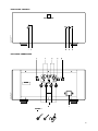 3
3
-
 4
4
-
 5
5
-
 6
6
-
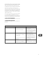 7
7
-
 8
8
-
 9
9
-
 10
10
-
 11
11
-
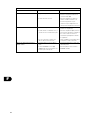 12
12
-
 13
13
-
 14
14
-
 15
15
-
 16
16
-
 17
17
-
 18
18
-
 19
19
-
 20
20
-
 21
21
-
 22
22
-
 23
23
-
 24
24
-
 25
25
-
 26
26
-
 27
27
-
 28
28
-
 29
29
-
 30
30
-
 31
31
-
 32
32
-
 33
33
-
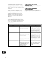 34
34
-
 35
35
-
 36
36
-
 37
37
-
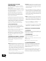 38
38
-
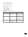 39
39
-
 40
40


NAD S200 Le manuel du propriétaire
- Catégorie
- Haut-parleurs de la barre de son
- Taper
- Le manuel du propriétaire
dans d''autres langues
- italiano: NAD S200 Manuale del proprietario
- English: NAD S200 Owner's manual
- español: NAD S200 El manual del propietario
- Deutsch: NAD S200 Bedienungsanleitung
- português: NAD S200 Manual do proprietário
- svenska: NAD S200 Bruksanvisning
Documents connexes

Autres documents
-
VINCENT SV-238MK Le manuel du propriétaire
-
-
Yamaha P2050 Le manuel du propriétaire
-
-
-
-
-
-
Klipsch Jubilee Le manuel du propriétaire