Blaze King Ashford 20.2 Le manuel du propriétaire
- Catégorie
- Poêle à bois
- Taper
- Le manuel du propriétaire

180-AF20.2 v1.03 August 20, 2019
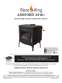
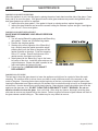
ASHFORD AF20.2
SOLID FUEL WOOD CATALYTIC STOVE
0142WS013E
0142WS013S
The authority having jurisdiction (such a municipal building department, fi re department, etc.) should be
consulted before installation to determine the need to obtain a permit.
Pour la version française de nos manuels S.V.P. vous référez à notre site web: www.blazeking.com
Manufactured By
Valley Comfort Systems Inc., 1290 Commercial Way, Penticton, BC, V2A 3H5, Canada
Phone: 250-493-7444 w Fax: 250-493-5833 w www.blazeking.com w [email protected]
OPERATION & INSTALLATION MANUAL
Installer: Please complete the details on the back cover
and leave this manual with the homeowner.
Homeowner: Please SAVE THESE INSTRUCTIONS for future reference.
U.S. Environmental Protection Agency certi ed to comply with 2020 particulate emission standards using crib wood.

180-AF20.2 v1.03 August 20, 2019
Page 2
AF20.2
TABLE OF CONTENTS
INTRODUCTION _____________________________________________________________ 4
SPECIFICATIONS _____________________________________________________________ 5
EMISSIONS __________________________________________________________________ 5
APPLIANCE DIMENSIONS ______________________________________________________ 6
CERTIFICATION LABEL ________________________________________________________ 7
SAFETY PRECAUTIONS ________________________________________________________ 8
INSTALLATION INSTRUCTIONS _________________________________________________ 11
PARTS INCLUDED WITH THE ASHFORD ................................................................................... 11
OPTIONAL EQUIPMENT ............................................................................................................... 11
FLOOR PROTECTION .................................................................................................................... 11
MINIMUM CLEARANCES for AF20.2 ............................................................................................ 12
COMBUSTION AIR ......................................................................................................................... 13
DRAFTING PERFORMANCE ......................................................................................................... 13
ROLE OF THE CHIMNEY ............................................................................................................... 13
VENTING SYSTEMS ...................................................................................................................... 14
RECOMMENDED FLUE HEIGHTS ................................................................................................ 17
MOBILE HOME (AND RESIDENTIAL ALCOVE INSTALLATIONS) ........................................... 18
OPTIONAL ACCESSORIES ............................................................................................................. 19
DOOR INSTALLATION AND CHANGE-OUT ............................................................................... 20
OPERATING INSTRUCTIONS ___________________________________________________ 21
INTRODUCTION ............................................................................................................................ 21
YOUR FIRST FIRE! .......................................................................................................................... 21
BYPASS ............................................................................................................................................ 21
CATALYTIC THERMOMETER ....................................................................................................... 21
THERMOSTAT ................................................................................................................................ 22
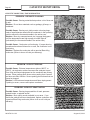
SELECTING WOOD ........................................................................................................................ 22
HOW TO USE MOISTURE METERS .............................................................................................. 23
EFFICIENCY .................................................................................................................................... 23
LIGHTING THE FIRE ..................................................................................................................... 24
RELOADING PROCEDURE (with the catalyst temperature in the ACTIVE ZONE) ....................... 25
RELOADING PROCEDURE (with the catalyst temperature still in the INACTIVE ZONE) ............. 25
FAN OPERATION .......................................................................................................................... 25
ICE - FORMATION AND PREVENTION ....................................................................................... 25
OPTIMAL THERMOSTAT SETTING ............................................................................................. 26
WOOD BURNING IN THE SHOULDER SEASON ......................................................................... 26
CATALYST MONITORING ______________________________________________________ 27
CATALYTIC COMBUSTOR, TESTING ........................................................................................... 27
CATALYTIC COMBUSTOR, CLEANING ....................................................................................... 27
CATALYTIC COMBUSTOR, TROUBLESHOOTING ...................................................................... 28
CATALYTIC COMBUSTOR, REPLACEMENT ............................................................................... 30

180-AF20.2 v1.03 August 20, 2019
Page 3
AF20.2
TABLE OF CONTENTS
MAINTENANCE ______________________________________________________________ 33
RUN-AWAY OR CHIMNEY FIRE .................................................................................................... 33
ASH REMOVAL ............................................................................................................................... 34
LOADING DOOR GASKET INSPECTION...................................................................................... 35
LOADING DOOR GASKET REPLACEMENT................................................................................. 35
BYPASS DOOR GASKET INSPECTION .......................................................................................... 35
BYPASS DOOR GASKET REPLACEMENT ..................................................................................... 36
DOOR GLASS GASKET INSPECTION ........................................................................................... 37
DOOR GLASS GASKET REPLACEMENT ...................................................................................... 37
DOOR GLASS, CLEANING ............................................................................................................. 37
LOADING DOOR TENSION ADJUSTMENT ................................................................................. 38
OPTIONAL FAN ASSEMBLY .......................................................................................................... 39
CARE OF SURFACES ....................................................................................................................... 39
CATALYTIC THERMOMETER ..................................................................................................... 39
THERMOSTAT ................................................................................................................................ 39
TROUBLESHOOTING __________________________________________________________ 40
REPLACEMENT PARTS ________________________________________________________ 43
WARRANTY _________________________________________________________________ 47
INSTALLER NOTES ____________________________________________________________ 52

180-AF20.2 v1.03 August 20, 2019
Page 4
AF20.2
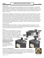
INTRODUCTION
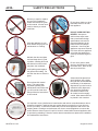
• THIS APPLIANCE IS HOT WHEN OPERATED AND CAN CAUSE SEVERE BURNS IF CONTACTED.
ANY CHANGES OR ALTERATIONS TO THIS APPLIANCE OR ITS CONTROLS CAN BE DANGEROUS AND IS PROHIBITED BY
FEDERAL AND STATE LAWS.
• Do not operate appliance before reading and understanding operating instructions. Failure to operate appliance according to operating
instructions could cause fi re or injury.
• Before installing this appliance, contact the local building or fi re authority and follow their guidelines.
• This appliance must be installed by a qualifi ed installer.
• Risk of burns. The appliance should be turned off and cooled before servicing.
• Do not operate without fully assembling all components.
• Do not let the appliance become hot enough for any part to glow red.
• Do not install damaged, incomplete or substitute components.
• Risk of cuts and abrasions. Wear protective gloves and safety glasses during installation. Sheet metal edges may be sharp.
• Children and adults should be alerted to the hazards of high surface temperature and should stay away to avoid burns or clothing
ignition.
• Young children should be carefully supervised when they are in the same room as the appliance. Toddlers, young children and
others may be susceptible to accidental contact burns. A physical barrier is recommended if there are at risk individuals in the house.
To restrict access to an appliance or appliance, install an adjustable safety gate to keep toddlers, young children and other at risk
individuals out of the room and away from hot surfaces.
• Clothing or other fl ammable material should not be placed on or near the appliance. Objects placed in front of the appliance must be
kept a minimum of 48” away from the front face of the appliance.
• Due to high temperatures, the appliance should be located out of traffi c and away from furniture and draperies.
• Ensure you have incorporated adequate safety measure to protect infants / toddlers from touching hot surfaces.
• Even after the appliance is out, all surfaces, including the glass and/or any attachment will remain hot for an extended period of time.
• Check with your local hearth specialty dealer for safety hearth guards to protect children from hot surfaces. These guards must be
fastened to a wall and/or to the fl oor.
• Any safety guard removed for servicing must be replaced prior to operating the appliance.
• Under no circumstances should this appliance be modifi ed.
• This appliance must not be connected to a chimney fl ue pipe servicing a separate solid fuel burning appliance.
• Do not operate the appliance with the glass door removed, cracked or broken. Replacement of the glass should be done by a licensed
or qualifi ed service person.
• Do not strike or slam shut the appliance glass door.
• Operate only with the doors tightly closed.
• Appliance will over-fi re if door is not shut and latched.
• Only certifi ed doors / optional fronts / and surrounds for inserts with the unit are to be installed on the appliance.
• Keep the packaging material out of reach of children and dispose of the material in a safe manner. As with all plastic bags, these are
not toys and should be kept away from children and infants.
• If the appliance is not properly installed, a house fi re may result. Do not expose the appliance to the elements (rain, etc.) and keep the
appliance dry at all times.
• The chimney must be sound and free of cracks and obstructions. Clean your chimney regularly as required.
• Never use gasoline, gasoline-type lantern fuel, kerosene, charcoal lighter fl uid, or similar liquids to start or ‘freshen up’ a fi re in this
heater. Keep all such liquids well away from the heater while it is in use.
• Your appliance requires periodic maintenance and cleaning. Failure to maintain your appliance may lead to smoke spillage in your
home.
• Higher effi ciencies and lower emissions will generally result when burning air dried seasoned woods, as compared to wet, green or
freshly cut wood. Burning wet unseasoned wood can cause excessive creosote accumulation. When ignited it can cause a chimney
fi re that may result in a serious house fi re.
• The appliance is designed to burn seasoned wood only. Do not burn treated wood, coal, charcoal, colored paper, cardboard, solvents
or garbage.
• Burn wood directly on the fi rebricks. Do not use a grate or elevate the fi re.
• Do not store wood within appliance installation clearances or within the space required for re-fueling and ash removal.
• Ashes must be disposed in a metal container with a tight lid and placed on a non-combustible surface well away from the home or
structure until completely cool.
CALIFORNIA PROPOSITION 65
WARNING: This product can expose you to chemicals including
benzene, which is known to the State of California to cause cancer and
birth defects or other reproductive harm. For more information:
www.P65Warnings.ca.gov

180-AF20.2 v1.03 August 20, 2019
Page 5
AF20.2
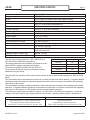
Model Ashford 20.2 (catalytic)
Height 30 3/8” (772 mm)
Width 26 3/4” (680 mm) (without removable bypass handle)
Depth 27 1/8” (689 mm) (without optional fan kit)
28 1/4” (718 mm) (with optional fan kit)
Flue collar 6” I.D.
Fire door opening 15 5/8” x 8” (397 mm x 204 mm)
Firebox depth 16” (407 mm) brick to brick, 18 1/2” (470 mm) brick to glass
Firebox width 17 1/2” (445 mm)
Firebox height 10 3/4” (273 mm)
Firebox capacity 1.8 cu. ft.
Recommended Fuel length 16” max. (407 mm)
Wood capacity (approximate): White oak - 45 lbs. (20.41 kg)
Fir - 30 lbs. (13.61 kg)
Construction 10 gauge & 1/4” fi rebox, brick lined
Cast iron outer shell
Shipping Weight (Firebox only) 450 lbs. (205 kg)
Chimney recommendation (Minimum) 15’ from stove top to chimney cap: Insulated liner recommended
SPECIFICATIONS
This unit was tested and listed UL 1482-11(R2015) and
ULC-S627-00 by OMNI-Test Laboratories.
This manual describes the installation and operation of the
Ashford AF20.2 catalytic equipped wood heater.
This heater is certifi ed to comply with the 2020 U.S.
Environmental Protection Agency’s particulate emission
standards using crib wood.
Under specifi c test conditions this heater has been shown to deliver heat at rates ranging from 8900 to 29785
Btu/hr.
This wood heater has a manufacturer-set minimum low burn rate that must not be altered. It is against federal
regulations to alter this setting or otherwise operate this wood heater in a manner inconsistent with operating
instructions in this manual.
This wood heater contains a catalytic combustor, which needs periodic inspection and replacement for proper
operation. It is against federal regulations to operate this wood heater in a manner inconsistent with operating
instructions in this manual, or if the catalytic element is deactivated or removed.
The combustor supplied with this heater is either a 115-0336A-M or 115-0556 metal combustor. Consult the
catalytic combustor warranty also supplied with this wood heater. Warranty claims should be addressed to:
in Canada in USA
Blaze King Industries / Valley Comfort Systems
Warranty Department, 1290 Commercial Way
Penticton, BC Canada V2A 3H5, Ph: 250-493-7444
Blaze King Industries
Warranty Department, 146A Street
Walla, Walla, Washington 99362, Ph: 509-522-2730
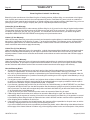
EMISSIONS CO Average(%) g/hr
Low Burn 0.20 0.22
Med-low Burn 0.14 0.58
Med-high Burn 0.25 0.93
High Burn 0.23 1.53
EPA emission rate weighted average .73 g/hr

180-AF20.2 v1.03 August 20, 2019
Page 6
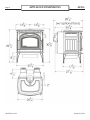
AF20.2
APPLIANCE DIMENSIONS

180-AF20.2 v1.03 August 20, 2019
Page 7
AF20.2
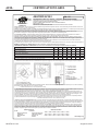
CERTIFICATION LABEL
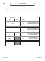
MINIMUM CLEARANCES TO COMBUSTIBLES (See owners manual for complete description of all requirements)
DÉGAGEMENTS MINIMUM AUX COMBUSTIBLES (voir les directives d’installation pour la description complète de toutes les conditions)
Residential Installations / Installations Résidentielles
ABCDEF J
Roof exit, parallel and corner.
Sortie de toit, parallèle et coin.
12.75”
324 mm
6.5”
166 mm
26.125”
664 mm
15.875”*
404 mm
6”
153 mm
18.125”*
461 mm
37”
940 mm
Wall exit, parallel and corner.
Sortie de mur, parallèle et coin.
12.75”
324 mm
6.5”
166 mm
26.125”
664 mm
15.875”*
404 mm
6”
153 mm
18.125”*
461 mm
37”*
940 mm
Alcove roof exit. Fan kit required.
Sortie de toit en alcôve. Kit de ventilateur requise.
12.75”
324 mm
6.5”
166 mm
26.125”
664 mm
15.875”*
404 mm
37”
940 mm
Mobile Home Installations / Installation pour Maison Mobile
Roof exit, parallel and corner. Fan kit and outside air kit required.
Sortie de toit, parallèle et en coin. Kit de ventilateur et kit d’air extérieur requis.
12.75”
324 mm
6.5”
166 mm
26.125”
664 mm
15.875”*
404 mm
6”
153 mm
18.125”*
461 mm
37”
940 mm
*Check with local codes and pipe manufacturers for pipe clearances. In Canada 18” clearances from single wall pipe is required.
* Vérifi er avec le code du bâtiment local et avec le manufacturier de tuyaux pour les dégagements. Au Canada un dégagement de 18 po est exigé pour un tuyau à simple paroi.
POUR PRÉVENIR UN INCENDIE - Installer et employer seulement selon le manuel d’installation de Blaze King. Contacter les autorités locales en bâtiments ou en matière de
prévention d'incendies au sujet des normes d'inspection et d'installation dans votre secteur. La dimension des conduits de cheminée est de 6”.
CHEMINÉE: NE PAS CONNECTER CETTE UNITÉ A UNE CONDUITE DE CHEMINÉE SERVANT UN AUTRE APPAREIL. Excepté pour les situations détaillées ci-dessous, employer
une cheminée de 6” homologuée par le fabricant à des fi ns d'utilisation pour combustibles solides conformément à la norme ULC629 au Canada ou UL-103HT aux Etats-Unis ou
employer une cheminée en maçonnerie de type résidentiel. L'installation dans une maison mobile, en espace restreint ou dans des endroits à faible dégagement, requiert l'utilisation
de connecteurs muraux à doubles parois et ayant une épaisseur 6” pour la cheminée.
Ceux-ci doivent être homologués par le fabricant à des fi ns d'utilisation pour combustibles solides conformément à la norme ULC629 au Canada ou UL-103HT aux Etats-Unis.
L'installation dans une maison mobile est permise seulement avec une sortie passant par le toit.
Ne pas installer dans une chambre à coucher. Passer à travers un mur ou un plafond requiert une méthode spécifi que décrite dans les instructions et dans le code local du bâtiment.
BLAZE KING CATALYST STOVE - POÊLE À BOIS CATALYTIQUE
ROOM HEATER, SOLID FUEL TYPE, ALSO FOR USE IN MOBILE HOMES. / APPAREIL APPROUVÉ DE TYPE CARBURANT SOLIDE,
AUSSI ADAPTÉ POUR INSTALLER DANS UNE MAISON MOBILE.
SUITABLE FOR MOBILE-HOME INSTALLATION. / CONCU POUR MAISONS MOBILES.
MODEL / MODÈLE: AF20.2
Tested to / Testé: UL 1482-11(R2015) / ULC S627-00
CERTIFIED IN BOTH UNITED STATES AND CANADA / CERTIFIÉ POUR LES ÉTATS-UNIS ET LE CANADA
La protection de plancher peut être de n’importe quel matériel non combustible ou Protecteur de plancher approuvé, et doit se prolonger au moins de 18” (456 mm) au Canada ou
16" (406 mm) aux États-Unis devant la porte de chargement: Aux États-Unis, la taille minimum est de 32” x 40 1/8” (813 mm x 1019 mm)
Au Canada la taille minimum est 42 3/4” x 50 1/8” (1086 mm x 1273 mm)
L’AGENCE DE PROTECTION ENVIRONNEMENTALE DES U.S. - Certifi é conformément aux normes d'émission de particules 2020 , en utilisant du bois machiné (méthodes d'essai
EPA 28R / 5G, ASTM E2515 et ASTM E2780, avec un taux d'émission de 0.73 g /hre). Cet appareil de chauff age au bois nécessite des inspections périodiques et des réparations pour
un fonctionnement adéquat. Consulter le manuel du propriétaire pour plus d’informations. Il est contre les règlements fédéraux de faire fonctionner cet appareil de chauff age à
l’encontre des instructions d’utilisation fournies dans le manuel du propriétaire, ou si l’élément catalytique est enlevé ou désactivé.
*Utiliser le uniquement avec les portes fermées. Ouvrir la porte pour alimenter le feu SEULEMENT. *Ne pas obstruer l’entrée d’air de combustion. Fournir l'apport d’air extérieur
adéquat pour alimenter la combustion. Ne pas obstruer l’espace sous l'appareil. Utiliser uniquement avec des combustibles solides - ne pas brûler aucun autre combustible, ce
qui peut rendre le catalyseur de la chambre à combustion inactif. La performance du catalyseur ou sa longévité n’a pas été évaluée dans le cadre de la certifi cation. Numéro du
catalyseur: 115-0336A-M ou 115-0556. *Employer seulement le verre en céramique d’une épaisseur de 5mm si le remplacement est nécessaire. Attention: Ce poêle à bois doit être
installé avec les pieds de support attachés et fi xés au poêle tel que montré dans les instructions d'installation.
PREVENT HOUSE FIRES - Install and use only in accordance with Blaze King’s installation and operation instructions. Contact local building or fi re offi cials about restrictions and
installation inspection in your area. The fl ue size is 6".
CHIMNEYS: DO NOT CONNECT THIS UNIT TO A CHIMNEY FLUE SERVING ANOTHER APPLIANCE. Except for installation detailed below, use 6” listed factory built chimney suitable
for use with solid fuels and conforming to, ULC629 in Canada or UL-103HT in the USA or a masonry residential type chimney.
Mobile Home, residential close clearance, and residential alcove installations require a 6” listed double wall close clearance chimney connector, with matching listed factory built
chimney suitable for use with solid fuels and conforming to, ULC629 in Canada or UL-103HT in the USA. Mobile Home installations are only allowed with a roof exit.
Do not install in a sleeping room. Passing through a wall or ceiling requires special methods: see instructions and local building codes.
SN - 25.
ASHFORD AF20.2
170-0238 [02 19]
G - 2 5/8” (67 mm) in U.S.A.
8” (203 mm) in Canada
H - 16” (406 mm) in U.S.A.
18” (456 mm) in Canada
I - 0” (0 mm) in U.S.A.
8” (203 mm) in Canada
K - 18” (456 mm) *
ALCOVE
min. width / min. largeur
max. depth / min. profondeur
min. height above stove top / hauteur
min. au-dessus du poêle
52”
48”
37”
MANUFACTURE DATE
JAN FEB MAR APR MAY JUN
JUL AUG SEP OCT NOV DEC
2019 2020 2021 2022 2023 2024
MANUFACTURED IN
USA:
Blaze King Industries
146A Street
Walla Walla, WA.
99362
CANADA:
Valley Comfort Systems
1290 Commercial Way
Penticton, B.C.
V2A 3H5
Floor protection may be any non-combustible material or Listed Floor Protector, and must extend at least 18” (456 mm) in Canada or 16” (406 mm) in U.S.A., in front of the loading
door opening: In USA, minimum size is 32” x 40 1/8” (813 mm x 1019 mm)
In Canada, minimum size is 42 3/4” x 50 1/8” (1086 mm x 1273 mm)
US ENVIRONMENTAL PROTECTION AGENCY Certifi ed to comply with 2020 particulate emission standards using crib wood. (EPA test methods 28R/5G with an emission-rate of .73 g/
hr). This wood heater needs periodic inspection and repair for proper operation. Consult the owner’s manual for further information. It is against federal regulations to operate this
wood heater in a manner inconsistent with operating instructions in the owner’s manual, or if the catalytic element is deactivated or removed.
*ONLY OPERATE WITH DOORS CLOSED. Open door to feed fi re ONLY. *DO NOT OBSTRUCT COMBUSTION AIR OPENINGS. Do not obstruct the space beneath the heater. For
Use with solid wood fuel only - do not burn other fuels, this may make the catalyst in the combustor inactive. The performance of the catalytic device or its durability has not been
evaluated as part of the certifi cation. Combustor part number: 115-0336A-M or 115-0556. Provide adequate outside air for combustion. *Replace with only ceramic glass, 5 mm.
Thickness. WARNING: This wood heater must be installed with the legs secured and attached to the stove as shown in the installation instructions.
0142WS013E
0142WS013S

180-AF20.2 v1.03 August 20, 2019
Page 8
AF20.2
This appliance must be connected to a listed high temperature (ULC629 IN CANADA OR
UL-103HT IN THE USA) residential type factory built solid fuel chimney or an approved
masonry chimney with a fl ue liner.
Chimney and chimney connector must be in good condition and kept clean.
NEVER vent the stove to other rooms of the building. Must be vented to the outside ONLY.
NEVER use a chimney or chimney connector smaller then the stove exhaust, unless
approved by your local inspector.
NEVER vent the stove into a “Class B” gas vent chimney.
DO NOT CONNECT IN CONJUNCTION WITH ANY AIR DISTRIBUTION DUCTWORK
UNLESS SPECIFICALLY APPROVED FOR SUCH INSTALLATIONS.
Inspect the chimney connector and chimney regularly during each burning season and
clean when necessary.
DO NOT CONNECT THIS UNIT TO A CHIMNEY FLUE SERVING ANOTHER APPLIANCE.
NEVER intentionally start a chimney fi re to clean the fl ue.
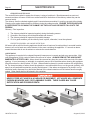
When installed in a mobile home, this appliance must be bolted to the fl oor and provided
with outside air.
WARNING: DO NOT INSTALL IN A SLEEPING ROOM
CAUTION: THE STRUCTURAL INTEGRITY OF THE MOBILE HOME
FLOOR, WALL, AND CEILING/ROOF MUST BE MAINTAINED.
Check with local building offi cials.
If the Optional Fan Kit is
installed, connect this unit to
a properly grounded, 110-volt
electrical outlet. Do not route
the power cord in front of or
under the appliance.
Do not make any changes or
modifi cations to an existing
masonry fi replace or chimney
to install this appliance. Do
not make any changes to
the appliance to increase
combustion air.
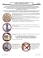
SAFETY PRECAUTIONS
IF THIS BLAZE KING APPLIANCE IS NOT PROPERLY INSTALLED OR OPERATED, A HOUSE FIRE MAY
RESULT. TO REDUCE THE RISK OF FIRE, FOLLOW THE INSTALLATION INSTRUCTIONS. CONTACT LOCAL
BUILDING OR FIRE OFFICIALS ABOUT RESTRICTIONS AND INSTALLATION INSPECTION
REQUIREMENTS IN YOUR AREA.
PLEASE READ THIS ENTIRE MANUAL BEFORE YOU INSTALL AND USE YOUR NEW APPLIANCE. FAILURE TO
FOLLOW INSTRUCTIONS MAY RESULT IN PROPERTY DAMAGE, BODILY INJURY, OR EVEN DEATH.

180-AF20.2 v1.03 August 20, 2019
Page 9
AF20.2
Never try to repair or replace
any part of this appliance
unless instructions are given
in this manual. All other work
must be done by a trained
technician.
Allow the appliance to cool
down before carrying out any
maintenance or cleaning.
Maintain the door and glass
seal and keep them in good
condition. A leaking door seal
will shorten burn times and
may harm the combustor.
Avoid placing wood against
the glass when loading. Do
not slam the door or strike the
glass.
Do not throw this manual
away. This manual has
important operating and
maintenance instructions that
you will need at a later time.
Always follow the instructions
in this manual.
Do not place clothing or other
fl ammable items on or near
this appliance.
Do not use a grate or other
device to elevate the fi re off of
the fi rebox fl oor. Burn the fi re
directly on the bricks.
Ashes should be placed in a
steel container with a tightly
fi tting lid and moved outdoors
immediately. If the ashes are
disposed of by burial in soil or
otherwise locally dispersed,
they should be retained in
the closed container until
all cinders have thoroughly
cooled. Other waste shall not
be placed in this container.
SAFETY PRECAUTIONS
It is required in some jurisdictions to install smoke and carbon monoxide detectors where
heaters are installed. Install at least one smoke detector on each fl oor of your home to
ensure your safety. It should be located away from the wood appliance and close to the
sleeping areas. Locating a smoke detector too close to a wood appliance can cause the
smoke detector alarm to sound if a puff of smoke is emitted while the wood appliance door
is open during reloading. Follow the smoke detector manufacturers placement, installation,
and maintenance instructions.
DO NOT OVER FIRE THIS
HEATER. Attempts to
achieve heat output rates
that exceed heater design
specifi cations can result in
permanent damage to the
heater and to the catalytic
combustor. Over fi ring the
appliance may cause a house
fi re. Never burn the appliance
so hot that the appliance or
chimney connector begins to
glow.

180-AF20.2 v1.03 August 20, 2019
Page 10
AF20.2
Never burn the appliance
with the loading door open.
Leaving the door cracked
open may damage the
combustor.
Never block free airfl ow
through vents on this
appliance.
HOT WHILE IN OPERATION.
KEEP CHILDREN,
CLOTHING AND FURNITURE
AWAY.
CONTACT MAY CAUSE SKIN
BURNS.
Do not touch the appliance
when it is hot and educate all
children of the danger of a
high temperature appliance.
Young children should be
supervised when they are
in the same room as the
appliance.
This appliance must be
properly installed to prevent
the possibility of a house
fi re. The instructions must
be strictly adhered to. Do not
use makeshift methods or
compromise in the installation.
Do not use chemicals or fl uids
to start the fi re. Never use
gasoline, gasoline-type lantern
fuel, kerosene, charcoal lighter
fl uid, or similar liquids to start or
‘freshen up’ a fi re in this heater.
Keep all such liquids well away
from the heater while it is in use.
Some fuels could generate
carbon monoxide and are very
dangerous.
Keep furniture, curtains,
wood, paper and other
combustibles a minimum of
48in (1219mm) away from
the front of the appliance.
ALSO, DO NOT STORE
COMBUSTIBLES UNDER
THE APPLIANCE (WOOD,
PAPER etc.).
Contact local building offi cials
to obtain a permit and
information on any installation
restriction or inspection
requirements in your area.
Notify your insurance
company as well.
SAFETY PRECAUTIONS
This appliance is designed and approved for burning cord wood only. DO NOT burn trash,
garbage; artifi cial or paper logs; gift wrappings; coal; lighter fl uids; chemical cleaners;
chemical starters; treated or painted wood; salt water driftwood or foil-backed paper such
as gum wrappers or cigarette packages; lawn clippings or yard waste; materials containing
rubber (including tires), plastic, asbestos; waste petroleum products, paints or paint
thinners, or asphalt products; construction or demolition debris; railroad ties or pressure-
treated wood; manure or animal remains; unseasoned wood or paper products, cardboard,
plywood, or particleboard. The prohibition against burning these materials does not prohibit
the use of fi re starters made from paper, cardboard, saw dust, wax and similar substances
for the purpose of starting a fi re in an aff ected wood heater. Burning these materials may
result in the release of toxic fumes or render the heater ineff ective and cause smoke.
Burn natural wood only. It will void all warranties and safety listings and may damage the
combustor.

180-AF20.2 v1.03 August 20, 2019
Page 11
AF20.2
INSTALLATION INSTRUCTIONS
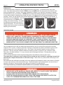
FLOOR PROTECTION
If the stove sits on a combustible fl oor, a non-combustible shield must be used underneath the
stove and extending 16” out from the front and 8” on either side of the fuel-loading door in the
USA. In Canada a non-combustible shield must be used underneath the stove and extending 8”
on either side and rear and 18” out in front of the loading door.
A non-combustible shield is also required underneath the chimney connector and extending at
least 2” (50.8mm) on either side of the chimney connector.
See the next page for minimum sizes depending on model. This fl oor protection is required
to prevent sparks from falling onto the combustible fl oor. See CSA B365-M87). This product
does not require thermal hearth pad protection.
Blaze King grants no warranty, implied or
stated, for the installation or maintenance of the
appliance and assumes no responsibility of any
consequential damage(s).
PARTS INCLUDED WITH THE ASHFORD
1. Poker
2. Manual kit (w/ warranty cards, thermometer, bypass handle)
OPTIONAL EQUIPMENT
1. Fan kit (Z2814) 2. Side shelf (Z2853)
3. Outside air kit (Z1726B)
• BEFORE INSTALLING THIS APPLIANCE, CONTACT THE LOCAL BUILDING OR FIRE OR OTHER
AUTHORITY HAVING JURISDICTION AND FOLLOW THEIR GUIDELINES.
• THIS APPLIANCE MUST BE INSTALLED BY A QUALIFIED INSTALLER. FOLLOW THE
INSTALLATION DIRECTIONS. DO NOT OPERATE WITHOUT FULLY ASSEMBLING ALL
COMPONENTS.
• IF THIS APPLIANCE IS NOT PROPERLY INSTALLED, A HOUSE FIRE MAY RESULT.
• THIS APPLIANCE IS HOT WHEN OPERATED AND CAN CAUSE SEVERE BURNS IF
CONTACTED. CHILDREN AND PETS MUST BE KEPT FROM TOUCHING THE APPLIANCE
WHEN IT IS HOT.
• COMBUSTIBLE MATERIAL SUCH AS FIRE WOOD, WET CLOTHING, ETC. PLACED TOO CLOSE
CAN CATCH FIRE. OBJECTS PLACED IN FRONT OF THE APPLIANCE MUST BE KEPT A
MINIMUM OF 48”(1219 MM) FROM THE FRONT OF THE APPLIANCE.

180-AF20.2 v1.03 August 20, 2019
Page 12
AF20.2
INSTALLATION INSTRUCTIONS
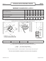
MINIMUM CLEARANCES for AF20.2
G = 2 5/8” (67mm) in USA
8” (203mm) in Canada
H = 16” (406mm) in USA
18” (456mm) in Canada
I = 0” (0mm) in USA
8” (203mm) in Canada
K = 18” (456mm) for single wall pipe in Canada
Ember protection shield (not required to have an insulation value)
is to be listed under UL 1618-2009 (type 1) and must have a minimum size of:
In USA: 32” x 40 1/8” (813 x 1019 mm)
In Canada: 42 3/4” x 50 1/8” (1086 x 1273 mm)
Min. Alcove minimum width 52”, maximum depth 48”, minimum height above stove top 37”
This stove must be installed in compliance with all local codes and regulations.
Residential Installations A B C D E F J
Roof exit, parallel and corner.
12.75”
324 mm
6.5”
166 mm
26.125”
664 mm
15.875”*
404 mm
6”
153 mm
18.125”*
461 mm
37”
940 mm
Wall exit, parallel and corner.
12.75”
324 mm
6.5”
166 mm
26.125”
664 mm
15.875”*
404 mm
6”
153 mm
18.125”*
461 mm
37”*
940 mm
Alcove, roof exit. Fan kit required.
12.75”
324 mm
6.5”
166 mm
26.125”
664 mm
15.875”*
404 mm
37”
940 mm
Mobile Home Installation
Roof exit, parallel and corner. Fan kit and outside air kit required.
12.75”
324 mm
6.5”
166 mm
26.125”
664 mm
15.875”*
404 mm
6”
153 mm
18.125”*
461 mm
37”
940 mm
* Check with local codes and pipe manufacturer for pipe clearances. In Canada, 18” clearances from single wall pipe is required.
Clearances may only be reduced by means approved by the regulatory authority

180-AF20.2 v1.03 August 20, 2019
Page 13
AF20.2
INSTALLATION INSTRUCTIONS
COMBUSTION AIR
Ensure adequate combustion air allowing for all other exhausting type appliances in the dwelling (range hoods,
dryers, etc.). In air tight homes and modern constructions, careful considerations must be taken into account
when using a wood burning appliance. Heat recovery ventilators (HRV) systems along with constant running
fan motors in air handlers must be taken into account when balancing the system. Failure to do so may
result in air starvation, smoke spillage and carbon monoxide threats. Consult a HVAC specialist for proper
installation. Ensure adequate combustion air allowing for all other exhausting type appliances in the dwelling
(range hoods, dryers, etc.). In airtight houses it is recommended to install a fresh air inlet into the room where
the appliance is located, to prevent air starvation.
ROLE OF THE CHIMNEY
Without a proper installed chimney, this appliance will not burn correctly.
The role of the chimney is to pull the proper amount of air into the fi rebox for the purpose of complete
combustion. Incomplete combustion will lead to more smoke and pollution of the outside air. A proper
operating chimney will allow the user to enjoy peak performance at all burn operating levels from low to high.
Blaze King therefore recommends vertical installations with a minimum length of 15’ from stove top to chimney
cap. In all freestanding stove installations, use double wall stove pipe from the stove top to the ceiling support
box. The use of double wall stove pipe does allow for reduced clearances, however most importantly, it helps
to keep the chimney warm and improve draft.
For wall exits, the same suggestion applies. With the addition of the recommendation to use two 45 degree
elbows rather than a single 90 degree elbow. The use of two 45 degree elbows will allow for both a smoother
transition to the exterior chimney and will also shorten the horizontal run to the outside chimney. A minimum
36” rise is recommended prior to any elbows being used. When possible, outside chimney systems should
be isolated from direct exposure to winter weather by building a chase around the chimney, observing all
clearances as specifi ed by the venting manufacturer. Doing so will help to keep the chimney warmer and
improve draft. (see RECOMMENDED FLUE HEIGHTS)
DRAFTING PERFORMANCE
Draft is the force which moves air into the appliance up through the chimney. The amount of draft created by
your chimney depends upon length, off sets, insulating properties, obstructions (such as architectural design,
trees), local geography and other factors.
External forces, such as outdoor temperature, wind, barometric pressure, topography, or factors inside the
home (negative pressure from exhaust fans, chimneys, air infi ltration, etc) may adversely aff ect draft.
Too much draft may cause excessive temperatures in the appliance and may damage the heater. An
uncontrollable burn or excessive temperature indicates excessive draft.
Inadequate draft may cause back puffi ng (spillage) into the room and plugging of the chimney, chimney cap or
spark arrestor screen. Inadequate draft may cause smoke to leak into the room through appliance or chimney
connector joints. Poor draft can also lead to poor heat production and the inability for the combustor to remain
active in lower burn rate settings.
High effi ciency appliances, such as your Blaze King stove, may require some fi ne tuning of your chimney
system in order to maximize performance.
Blaze King cannot be responsible for external forces leading to less than optimal performance.

180-AF20.2 v1.03 August 20, 2019
Page 14
AF20.2
VENTING SYSTEMS
The venting system consists of a chimney connector and a chimney. These get extremely hot during use.
Temperatures inside the chimney may exceed 2000 degrees in the event of a creosote fi re. To protect against
the possibility of a house fi re, the chimney connector and chimney must be properly installed and maintained.
A listed thimble must be used when a connection is made through a combustible wall to a chimney. A chimney
support package must be used when a connection is made through the ceiling to a listed prefabricated
chimney. These accessories are absolutely necessary to provide safe clearances to combustible wall and
ceiling material.
This stove may be connected to a lined masonry chimney or a listed factory built chimney suitable for use with
solid fuels and conforming to, ULC629 in Canada or UL-103HT in the USA. Do not connect it to a chimney
serving another appliance. To do so will aff ect the safe operation of both appliances, and will void the stove
warranty. You must comply with the local authority having jurisdiction and/or in Canada, CSA installation
standard B365-M87.
The chimney connector must be 6” diameter, 24 MSG Black/Blue steel. Do not use aluminum or galvanized
steel. They cannot properly withstand the extreme temperatures of a wood fi re. The chimney connector
between the stove and the chimney should be as short and direct as possible.
The chimney connector must be attached to either an approved masonry chimney or one of the listed factory
built chimneys suitable for use with solid wood fuel. All joints must be tight and fastened with sheet metal
screws.
THE CHIMNEY CONNECTOR IS TO BE USED ONLY WITHIN THE ROOM, BETWEEN THE STOVE
AND CEILING / WALL. NEVER USE A CHIMNEY CONNECTOR TO PASS THROUGH AN ATTIC
OR ROOF SPACE, CLOSET OR SIMILAR CONCEALED SPACE, OR A FLOOR, OR CEILING. AN
EFFECTIVE VAPOR BARRIER MUST BE MAINTAINED AT THE LOCATION WHERE THE CHIMNEY
OR COMPONENT PENETRATES TO THE EXTERIOR OF THE STRUCTURE. ALWAYS MAINTAIN
THE MINIMUM CLEARANCES TO COMBUSTIBLES AS REQUIRED BY THE APPLICABLE BUILDING
CODES.
INSTALLATION INSTRUCTIONS

180-AF20.2 v1.03 August 20, 2019
Page 15
AF20.2
INSTALLATION INSTRUCTIONS
CONNECTION TO A METAL PREFABRICATED CHIMNEY
Refer to “RECOMMENDED FLUE HEIGHTS” chart for minimum fl ue height recommendations and ULC629
in Canada or UL-103HT in the USA for installation codes. When a metal prefabricated chimney is used, the
manufacturer’s installation instructions must be followed precisely. You must also purchase (from the same
manufacturer) and install the ceiling support package or wall pass through and “T” section package, fi re
stops (when needed), insulation shield, roof fl ashing, chimney cap, etc. Maintain the proper clearance to the
structure as recommended by the manufacturer. This clearance is usually a minimum of 2 inches, although it
may vary by manufacturer or for certain components.
There are basically two methods of metal chimney installation. One method is to install the chimney inside
the residence through the ceiling(s) and the roof. The other method is to install an exterior chimney that runs
up the outside of the residence (not recommended). If it is necessary to run the chimney outside, build an
outside chase around the chimney.
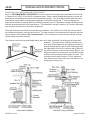
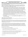
The chimney must be the required height above the roof or other obstruction for safety and for proper draft
operation. The requirement is that the chimney must
be at least 3 feet higher than the highest point where it
passes through the roof and at least 2 feet higher than
the highest part of the roof or structure that is within 10
feet of the chimney, measured horizontally (Fig. 1). The
height requirement is necessary in the interest of safety
and does not necessarily assure proper fl ue draft. Use
a minimum total system height of 15 feet, measured
from the stove fl ue collar to the top of the chimney, not
including the chimney cap.

180-AF20.2 v1.03 August 20, 2019
Page 16
AF20.2
INSTALLATION INSTRUCTIONS
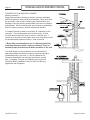
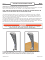
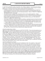
CONNECTION TO A MASONRY CHIMNEY
Masonry chimney***
Ensure that a masonry chimney meets the minimum standards
(NFPA) by having it inspected by a professional. Make sure there
are no cracks, loose mortar or other signs of deterioration and
blockage. Have the chimney cleaned before the stove is installed
and operated. When connecting the stove through a combustible
wall to a masonry chimney, special methods are needed.
In Canada, the wall cut away is to provide 18” clearance for the
connector. The resulting space must remain empty. A fl ush
mounted sheet metal cover may be used on one side only. If
covers are to be used on both sides, each cover must be mounted
on noncombustible spacers at least 1” clear of the wall.
***Blaze King recommends the use of a Stainless steel liner,
preferably insulated, inside a masonry chimney. This is to
maintain proper draft and overall better operation of the unit.
Your local dealer or local jurisdiction can provide details of
approved methods of passing a chimney connector through a
combustible wall in your area. In USA, the National Fire
Protection Association has minimum standards to comply
with. In Canada , this type of installation must conform to
CAN/CSA-B365, Installation Code for Solid Fuel Burning
Appliances and Equipment.

180-AF20.2 v1.03 August 20, 2019
Page 17
AF20.2
INSTALLATION INSTRUCTIONS
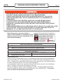
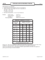
RECOMMENDED FLUE HEIGHTS
1. At sea level the minimum height is a 15 ft (4.6 m) straight run.
2. Add the following vertical height to the fl ue to compensate for:
45° elbow = 1.0 ft (.30 m)
90° elbow = 2.0 ft (.61 m)
“T” section= 3.0 ft (.91 m)
3. Each foot of horizontal run = 2 ft (.61 m) of vertical rise.
Example: One 90° elbow = 2ft (.61 m)
2ft Horizontal run = 4ft (1.2 m)
One base “T” = 3ft (.91 m)
Total height addition = 9ft (2.7 m) at sea level
MINIMUM RECOMMENDED FLUE HEIGHT
ELEVATION
ABOVE SEA
LEVEL
NUMBER OF ELBOWS
0 2 X 15° 2 X 30° 2 X 45°
0 - 1000 ft
0 - 305 m
15
4.6 m
16
4.9 m
18
5.5 m
19
5.8 m
1000 - 2000 ft
305 - 610 m
15.5
4.7 m
16.5
5.0 m
18.5
5.6 m
19.5
5.9 m
2000 - 3000 ft
610 - 914 m
16
4.9 m
17
5.2 m
19
5.8 m
20
6.1 m
3000 - 4000 ft
914 - 1219 m
16.5
5.0 m
17.5
5.3 m
19.5
5.9 m
20.5
6.2 m
4000 - 5000 ft
1219 - 1524 m
17
5.2 m
18
5.5 m
20
6.1 m
21
6.4 m
5000 - 6000 ft
1524 - 1829 m
17.5
5.3 m
18.5
5.6 m
20.5
6.2 m
21.5
6.6 m
6000-7000 ft
1829 - 2134 m
18
5.5 m
19
5.8 m
21
6.4 m
22
6.7 m
7000 - 8000 ft
2134 - 2438 m
18.5
5.6 m
19.5
5.9 m
21.5
6.6 m
22.5
6.9 m
NOTE: No more than one off set (two elbows allowed).
Two 45°elbows equal one 90° elbow
Please note: These are only guidelines. Please refer to the section in the manual pertaining to draft. Every
installation is unique and can be infl uenced by topographical and geographical phenomena.
The use of a manometer and an understanding of pressure planes and the stack eff ect are imperative in
planning and executing a successful installation.

180-AF20.2 v1.03 August 20, 2019
Page 18
AF20.2
INSTALLATION INSTRUCTIONS
In mobile home installations, the stove must be securely fastened to the fl oor using the tie-downs
provided in the outside air kit. Use the leg anchor kit (Z2872) to secure stove to fl oor.
ALSO, a #8 ground wire must be attached to the stove and an appropriate ground.
MOBILE HOME (AND RESIDENTIAL ALCOVE INSTALLATIONS)
Requires outside air kit, and either rear shield OR fan kit. (See next page for kits and part numbers). e outside
air kit is easiest to mount before the stove is installed. See instructions packed with each kit.
NOTE: UNDER NO CIRCUMSTANCES SHOULD THE FRESH AIR TUBE EVER BE INSTALLED
HIGHER THAN THE BOTTOM OF THE APPLIANCE FIREBOX FLOOR.
When a metal prefabricated chimney is used, the manufacturer’s installation instructions must be followed
precisely. You must also purchase (from the same manufacturer) and install the ceiling support package, re
stops (when needed), insulation shield, roof ashing, chimney cap, etc. Maintain the proper clearance to the
structure as recommended by the manufacturer.
e Chimney connector must be a listed double wall close clearance type. Insulated chimney components must
be a listed factory built chimney suitable for use with solid fuels and conforming to ULC629 in Canada and
UL-103HT in the USA. Single wall stove pipe is not allowed in mobile homes or alcove installations. For mobile
home, the chimney needs to be removable to allow for transportation of the mobile home.
DO NOT INSTALL IN SLEEPING ROOM. THE STRUCTURAL INTEGRITY OF THE MOBILE
HOME FLOOR, WALL AND CEILING / ROOF MUST BE MAINTAINED.

180-AF20.2 v1.03 August 20, 2019
Page 19
AF20.2
INSTALLATION INSTRUCTIONS
OPTIONAL ACCESSORIES
Outside air kit or fan kit are optional accessories, but are required for the following installations:
MOBILE HOME INSTALLATION — Requires outside air kit and fan kit
RESIDENTIAL ALCOVE — Requires fan kit
FAN KIT (Z2814)
The fan kit is REQUIRED FOR:
MOBILE HOME, any installation
RESIDENTIAL ALCOVE
NOTE: Fan kit should be installed before the stove is placed into position.
INSTALLATION: See instructions included with fan kit. Tools needed: Square (Robertson no. 2) screw
driver and a 5/32” allen wrench.
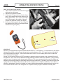
ELECTRICAL CONNECTION
Your Blaze King fan kit is equipped with a three-prong (grounded) plug to decrease shock hazard.
THIS PLUG SHOULD BE INSERTED DIRECTLY INTO A PROPERLY-GROUNDED, THREE-HOLE
RECEPTACLE. DO NOT CUT OR REMOVE THE GROUNDING PRONG FROM THIS PLUG. Do not
route the power cord in front or under the stove.
OUTSIDE AIR KIT (Z1726B)
REQUIRED FOR: MOBILE HOME (any installation)
The outside air inlet is a fl exible tube to bring outside air for combustion into the stove from outside the
residence, through the wall or up through the fl oor. The fl exible tube will allow some adjustment over or
around fl oor joists or plumbing. DO NOT CHANGE THE STRUCTURAL INTEGRITY OF THE FLOOR.
THE FRESH AIR TUBE AND OUTSIDE INLET SHOULD NEVER BE ABOVE THE BOTTOM LEVEL OF
THE FIREBOX. This air tube must be kept open at all times to provide outside air for combustion.
INSTALLATION:
See instructions included with the outside air kit. Tools needed: 1/4" or 3/8" drill motor, saber saw, saber
saw wood & metal blades, 5/16" nut driver or wrench, 7/16" wrench, small tube of hi-heat silicone.

180-AF20.2 v1.03 August 20, 2019
Page 20
AF20.2
INSTALLATION INSTRUCTIONS
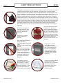
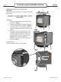
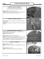
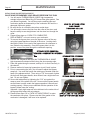
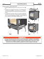
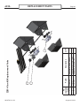
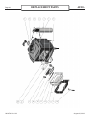
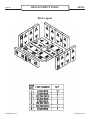
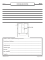
DOOR INSTALLATION AND CHANGE-OUT
(Z2910BK)
To install the door assembly or to change it out, follow
these steps:
WARNING: CAST PARTS ARE HEAVY, PLEASE
HOLD FIRMLY.
REMOVAL
1. Remove catalytic thermometer and cast top
from stove. (Fig A)
2. Remove left and right cast sides from stove
by lifting up and out from hangers. (Fig B) If
necessary use a 7/16” wrench to loosen the
top two bolts that secure the cast sides to the
fi rebox.
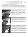
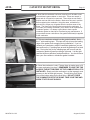
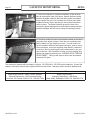
3. Remove the Cast iron front and door: This
operation requires two people as the cast
iron front is large and heavy. Loosen four
1/4-20 hex bolts and 1/4” spacer washers.
(Fig C) Use a 1/2” wrench. Have an
assistant support the front then remove the
bolts and washers
INSTALLATION
Perform the above tasks in reverse order.
La page est en cours de chargement...
La page est en cours de chargement...
La page est en cours de chargement...
La page est en cours de chargement...
La page est en cours de chargement...
La page est en cours de chargement...
La page est en cours de chargement...
La page est en cours de chargement...
La page est en cours de chargement...
La page est en cours de chargement...
La page est en cours de chargement...
La page est en cours de chargement...
La page est en cours de chargement...
La page est en cours de chargement...
La page est en cours de chargement...
La page est en cours de chargement...
La page est en cours de chargement...
La page est en cours de chargement...
La page est en cours de chargement...
La page est en cours de chargement...
La page est en cours de chargement...
La page est en cours de chargement...
La page est en cours de chargement...
La page est en cours de chargement...
La page est en cours de chargement...
La page est en cours de chargement...
La page est en cours de chargement...
La page est en cours de chargement...
La page est en cours de chargement...
La page est en cours de chargement...
La page est en cours de chargement...
La page est en cours de chargement...
-
 1
1
-
 2
2
-
 3
3
-
 4
4
-
 5
5
-
 6
6
-
 7
7
-
 8
8
-
 9
9
-
 10
10
-
 11
11
-
 12
12
-
 13
13
-
 14
14
-
 15
15
-
 16
16
-
 17
17
-
 18
18
-
 19
19
-
 20
20
-
 21
21
-
 22
22
-
 23
23
-
 24
24
-
 25
25
-
 26
26
-
 27
27
-
 28
28
-
 29
29
-
 30
30
-
 31
31
-
 32
32
-
 33
33
-
 34
34
-
 35
35
-
 36
36
-
 37
37
-
 38
38
-
 39
39
-
 40
40
-
 41
41
-
 42
42
-
 43
43
-
 44
44
-
 45
45
-
 46
46
-
 47
47
-
 48
48
-
 49
49
-
 50
50
-
 51
51
-
 52
52


Blaze King Ashford 20.2 Le manuel du propriétaire
- Catégorie
- Poêle à bois
- Taper
- Le manuel du propriétaire
dans d''autres langues
Documents connexes
-
 Blaze King Ashford 20.2 Le manuel du propriétaire
-
 Blaze King Chinook 30.2 Le manuel du propriétaire
-
 Blaze King AF30.1 Le manuel du propriétaire
-
 Blaze King Ashford 20.2 Le manuel du propriétaire
-
 Blaze King Sirocco 20.2 Le manuel du propriétaire
-
 Blaze King Sirocco 30.2 Le manuel du propriétaire
-
 Blaze King Sirocco 20.2 Le manuel du propriétaire
-
 Blaze King King 40 Le manuel du propriétaire
-
 Blaze King Chinook 20.2 Le manuel du propriétaire
-
 Blaze King King 40 Le manuel du propriétaire


Autres documents
-
DutchWest DW2500X02 Le manuel du propriétaire
-
DutchWest DutchWest CDW247001 Le manuel du propriétaire
-
-
-
 Malm Fireplaces Imperial Carousel Assembly And Installation Instructions Manual
-
 Frost King V447H Mode d'emploi
-
HOMCOM 844-713V81WT Mode d'emploi

