
Red Lion Controls 20 Willow Springs Circle York, PA 17406 USA 1.717.767.6511 [email protected]
USER MANUAL
SixTRAK IPm Controller
VersaTRAK IPm RTU
Installation and Maintenance
Contents at a Glance:
Section 1
Overview
3
Section 2
Assembly and Installation
7
Section 3
Power and ST-Bus Wiring
9
Section 4
Controller or RTUs
13
Section 5
Technical Specifications
16
Section 6
Maintenance Information
19
Section 7
Service Information
20
–
This manual applies to the following Red Lion products:
ST-IPM-####, VT-IPM-####

Red Lion Controls 20 Willow Springs Circle York, PA 17406 USA 1.717.767.6511 [email protected]
STATEMENT OF LIMITED WARRANTY
Red Lion, manufacturer of SixTRAK, VersaTRAK, RemoteTRAK and EtherTRAK products, warrants to Buyer that products
manufactured by Red Lion will be free from defects in material and workmanship. Red Lion’s obligation under this warranty will
be limited to repairing or replacing, at Red Lion’s option, the defective parts within 1 year of the date of installation, or within 18
months of the date of shipment from the point of manufacture, whichever is sooner. Products may be returned by Buyer only after
permission has been obtained from Red Lion. Buyer will prepay all freight charges to return any products to the repair facility
designated by Red Lion.
This limited warranty does not cover losses or damages that occur in shipment to or from Buyer or due to improper installation,
maintenance, misuse, neglect or any cause other than ordinary commercial or industrial applications, This limited warranty is in
lieu of all other warranties whether oral or written, expressed or implied. Red Lion’s liability shall not exceed the price of the
individual unit which is the basis of the claim. In no event shall Red Lion be liable for any loss of profits, loss of use of facilities or
equipment or other indirect, incidental or consequential damages.

Red Lion Controls 20 Willow Springs Circle York, PA 17406 USA 1.717.767.6511 [email protected]
INSTALLATION AND HAZARDOUS AREA WARNINGS
These products should not be used to replace proper safety interlocking. No software-based device (or any other solid-state device)
should ever be designed to be responsible for the maintenance of consequential equipment or personnel safety. In particular, Red
Lion disclaims any responsibility for damages, either direct or consequential, that result from the use of this equipment in any
application.
All power, input and output (I/O) wiring must be in accordance with Class I, Division 2 wiring methods and in accordance with the
authority having jurisdiction.
WARNING – EXPLOSION HAZARD – SUBSTITUTION OF COMPONENTS MAY IMPAIR SUITABILITY FOR CLASS
1, DIVISION 2.
WARNING – EXPLOSION HAZARD – WHEN IN HAZARDOUS LOCATIONS, DISCONNECT POWER BEFORE
REPLACING OR WIRING MODULES.
WARNING – EXPLOSION HAZARD – DO NOT DISCONNECT EQUIPMENT UNLESS POWER HAS BEEN SWITCHED
OFF OR THE AREA IS KNOWN TO BE NONHAZARDOUS.
AVERTISSEMENTS POUR INSTALLATION ET POUR ENDROITS DANGEREUX
Ces produits ne doivent pas être utilisés pour remplacer le verrouillage de sécurité approprié. Aucun dispositif basé sur un logiciel
(ou tout autre dispositif à l'état solide) devraient jamais être conçus pour être responsable de l'entretien de l'équipement consécutifs
ou la sécurité du personnel. En particulier, Red Lion décline toute responsabilité pour les dommages, directs ou indirects, résultant
de l'utilisation de cet équipement dans n'importe quelle application.
Tout courant, câblage entrée et sortie (I / O) doit être conforme aux méthodes de câblage à la Classe I, Division 2 et conformément
à l'autorité compétente.
AVERTISSEMENT – RISQUE D’EXPLOSION – LA SUBSTITUTION DE TOUT COMPOSANT PEUT NUIRE À LA
CONFORMITÉ DE CLASSE I, DIVISION 2.
AVERTISSEMENT – RISQUE D’EXPLOSION – LORSQUE DANS DES ENDROITS DANGEREUX, DÉBRANCHEZ LE
CORDON D'ALIMENTATION AVANT DE REMPLACER OU DE BRANCHER LES MODULES.
AVERTISSEMENT – RISQUE D’EXPLOSION – NE DÉBRANCHEZ PAS L'ÉQUIPEMENT À MOINS QUE
L'ALIMENTATION AIT ÉTÉ COUPÉE OU QUE L’ENVIRONNEMENT EST CONNU POUR ÊTRE NON DANGEREUX.
Note: All information in this document applies to SixTRAK IPm Open Controller, SixTRAK I/O
Controller, and VersaTRAK IPm RTU, except where otherwise noted. Refer to the Sixnet I/O
Tool Kit software online help system for detailed product specifications and configuration
settings.

Red Lion Controls 20 Willow Springs Circle York, PA 17406 USA 1.717.767.6511 [email protected]
Section 1
Overview
Introduction
The products covered by this manually are designed for use in industrial control and data
acquisition systems. Refer to the Sixnet Electronic catalog and the individual data sheets for
complete features and benefits. This user manual covers the aspects of hardware installation
and maintenance. For software features and capabilities please refer to Sixnet’s Electronic help
System accessible from within the Sixnet I/O Tool Kit software.
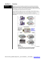
A typical Sixnet station consists of an AC to DC power supply; a Sixnet controller or RTU,
controller, or RTU; and modular I/O modules. The I/O modules can be interfaced via Ethernet
(EtherTRAK), RS485 (RemoteTRAK), or the ST-BUS (SixTRAK). Just about any
combination of these components along with third party hardware and software can be used to
make a system.
*more with an ET-GT-ST-# I/O concentrator
These Sixnet products offer practically unlimited
I/O expansion and communication connectivity.
Up to 20*
modules

Red Lion Controls 20 Willow Springs Circle York, PA 17406 USA 1.717.767.6511 [email protected]
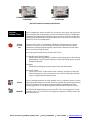
SixTRAK IPm Open Controller
ST-IPM-####
VersaTRAK IPm RTU
VT-IPM-####
Red Lion Products Covered by this Manual
Red Lion
Software Tools
Red Lion supplies the "mission oriented" tools you need for every step of your project from
the initial specification, through startup, and years of trouble free operation. Configuration
information flows between Sixnet Windows, saving you time (you don't have to enter data
multiple times) and dramatically reducing data entry errors. Refer to the on-line help in the
Sixnet I/O Tool Kit for complete details.
Sixnet
I/O Tool
Kit
The Sixnet I/O Tool Kit is a configuration, calibration and maintenance tool for Sixnet
hardware. Use the I/O Tool Kit to configure I/O features, perform channel-by-channel
calibrations in meaningful engineering units, and perform live diagnostics at each station.
Refer to the electronic help for details.
Here are the optional Feature Sets for the Sixnet I/O Tool Kit:
SCS (Scalable Control System) features
Includes importing, tag exporting, I/O transfers, advanced load options, and the IOmap
shared database. The SCS option is required to develop ISaGRAF programs, using the
ISaGRAF Workbench.
Datalogging
Includes Sixlog datalogging including automatic host and client transfers.
Open LINUX features
Gain access to LINUX-visible features in IPm controllers, including file loading and
advanced diagnostics. A library of functions to access the IPm I/O registers and other
services is supplied with this enhanced license.
Sixlog
Sixlog is datalogging software for Sixnet controller or RTUs, controllers, and RTUs. Data is
logged into protected memory in the unit. Then Sixlog uploads the data files and saves them
into ASCII format files that are easy to import into databases, spreadsheets and other
Windows applications. Access the Sixlog functions from within the Sixnet I/O Tool Kit.
ISaGRAF
The ISaGRAF Workbench allows you to write an IEC 61131 control program for a Sixnet
controller or RTU. All 5 of the IEC 61131 languages are supported, including Ladder Logic
and Function Blocks.

Red Lion Controls 20 Willow Springs Circle York, PA 17406 USA 1.717.767.6511 [email protected]
Getting Started
with Red Lion
Hardware
Following these steps will make installation and start-up easier.
Mount the Hardware
If you purchased a TrakPak packaged system, the complete enclosure is ready for
installation on any flat surface. If you purchased individual components, refer to the
following sections of this or the appropriate user manuals for information on installing
them into an enclosure.
Install ST-BUS or Communication Wiring to I/O Modules
Make ST-BUS wiring connections to any SixTRAK I/O modules. Refer to a following
section for ST-BUS wiring guidelines. Make the necessary communication connections
to any EtherTRAK or RemoteTRAK I/O modules. If you have a TrakPak packaged
system, all these connections have already been done for you.
Connect Power and I/O Wiring to the Modules
Connect AC power to the Red Lion or user supplied power supply. Make DC power
connections from the power supply to the Red Lion components. Make field wiring
connections to the Sixnet I/O modules and any peripheral equipment. Refer to the
appropriate user manuals for I/O connection details.
Install Communication Cabling
The units covered by this manual come with communication accessories. Snap the pre-
wired RJ45 to DB9 adapter to the RJ45 patch cord (not supplied). Connect this cable
between one of the serial RS232 ports (RJ45 connector) on your controller or RTU and
a serial RS232 port (DB9 connector) on your PC.
Fabricate and install RS232 and RS485 cables as needed to connect to other devices. If
you are using Ethernet units, install the correct cabling and peripherals. Refer to the
documentation for your Ethernet communication devices for details.
Apply Power
Power up the Red Lion components and related peripherals. Observe the status LED on
each unit. Typically a solid ON indicates proper operation. A blinking LED may
indicate that the unit needs to be configured. Refer to the appropriate Red Lion user
manual for details.
Configure Using the Sixnet I/O Tool Kit
Refer to the steps on the next page to create a hardware configuration for each Sixnet
station. Refer to the on-line help in the I/O Tool Kit for details.
Test the Hardware
Use the Test I/O window in the I/O Tool Kit program to verify proper I/O operation of
all Sixnet stations. Refer to the I/O Tool Kit on-line help system.
Configure Your PC Software to Communicate with the Sixnet station(s)
Refer to the documentation for your software.
If You Have Difficulty
If you experience startup trouble, refer to a following page in this document for some
troubleshooting tips or go to www.redlion.net. If you still need assistance then please
contact Red Lion.

Red Lion Controls 20 Willow Springs Circle York, PA 17406 USA 1.717.767.6511 [email protected]
Using Red Lion
Windows
Software
Below is a quick overview of using the Sixnet I/O Tool Kit. It is supplied on the Sixnet CD
and registering for Level 1 (basic features) is free.
Note: An expanded version of this page has been provided as on-line help. To access it,
click on the Getting Started icon in the I/O Tool Kit online help.
Basic Configuration: Run the Sixnet I/O Tool Kit program and create your panel layouts.
Then configure operating parameters for each Sixnet component, including channel tag
names. Link the SixTRAK I/O modules (if any) and load your configuration to the controller
or RTU. Assign virtual I/O modules and I/O transfers for any EtherTRAK or RemoteTRAK
modules you wish to have the controller or RTU poll. Save this information to a project file.
Using the Test I/O function, verify that you can read and write all your I/O.
Note: Set tag name restrictions in the Sixnet I/O Tool Kit program before creating tag
names to ensure compatibility when exporting them for usage in other Windows
applications.
Your Sixnet components are now ready to exchange I/O data with your Windows
applications via DDE, OPC, or direct DLL calls. (Refer to the "How to Access Sixnet I/O
From a Windows Application" topic in the Sixnet I/O Tool Kit online help.) If you will be
running a Windows application, then continue with the following steps.
Exporting I/O Definitions: (optional, requires the SCS feature set) Some Windows
applications, such as ISaGRAF, Citect and Intellution FIX, can import Sixnet tag names. If
your Windows application supports this feature, run the Sixnet I/O Tool Kit and open your
project file. Export your tag names to a file using the appropriate format.
Note: If you are exporting tag names for ISaGRAF, Citect or Intellution, you must create, or
already have, a project to export tag data into.
Datalogging: (optional, requires the Datalogging feature set) If you will be logging data in
the Sixnet controller or RTU, then create the appropriate datalog configuration(s) and load
them into the unit. Refer to the Sixlog topics in the Sixnet I/O Tool Kit online help for
details.
IEC 61131 Programming: (optional, requires the SCS feature set) If you are using the
ISaGRAF IEC1131 programming software, refer to the Sixnet ISaGRAF on-line help for
detailed instructions.
LINUX capabilities: (optional, requires the IPm Advanced feature set) If you are using
the advanced LINUX IPm capabilities, refer to the Sixnet I/O Tool Kit on-line help for
detailed instructions.

Red Lion Controls 20 Willow Springs Circle York, PA 17406 USA 1.717.767.6511 [email protected]
Safety
Standards
These industrial Ethernet Switches meet the following standards plus others:
Note: Some ratings may be pending on newer models. Contact Red Lion for latest info.
Sixnet, LLC is an ISO9001:2000 certified company (FM 65232) since 1996. These devices
are design, developed and manufactured per an ISO9001 quality management system.
Electrical safety –
CE per Low Voltage Directive and EN/IEC 61010-1
UL recognition per UL508 (UL File # E179490)
CSA per C22.2/14 (cUL File # E179490)
Markings:
Direct Current: 10-30VDC (minimum/maximum)
Protective Conductor Terminal
See warnings below.
Install the Managed Switches in accordance with local and national electrical codes.
Lightning Danger: Do not work on equipment during periods of lightning activity.
Do not connect a telephone line into one of the Ethernet RJ45 connectors.
EMC (emissions and immunity) –
CE per the EMC directive, EN 55022 or IEC 61326-1 or EN 61000-6-2/4
FCC part 15 and ICES 003; Class A. See FCC statement on previous page.
Marine, maritime and offshore –
These devices, when installed in an appropriately IP rated enclosure, comply with the ABS
standards which is similar to DNV No. 2.4 and equivalent Lloyds. See warning below.
For marine and maritime compliance, do not install this product within 5 meters of a
standard or a steering magnetic compass.
WEEE compliance –
These devices comply with the WEEE directive. Do not throw away these devices in the
standard trash. Contact Red Lion regarding proper disposal.
RoHS
RoHS compliance –
These devices comply with the RoHS directive and are consider lead and other hazardous
substance free.

Red Lion Controls 20 Willow Springs Circle York, PA 17406 USA 1.717.767.6511 [email protected]
Hazardous Locations –
CE per ATEX directive and EN60079-0/EN60079-15 (Zone 2);
For T4 rating, please see unit label or Declaration of Conformity
UL per UL1604 (Class I, Div. 2), Groups A,B,C,D (UL File # E192531)
CSA per C22.2/213 (Class 1, Div. 2), Groups A,B,C,D (cUL File # E192531)
See warnings below.
Consultez les avertissements ci-dessous.
WARNING
(EXPLOSION HAZARD)
SUBSTITUTION OF COMPONENTS MAY IMPAIR SUITABILITY
FOR CLASS 1, DIVISION 2 (ZONE 2).
WARNING
(EXPLOSION HAZARD)
WHEN IN HAZARDOUS LOCATIONS, DISCONNECT POWER
BEFORE REPLACING OR WIRING UNITS.
WARNING
(EXPLOSION HAZARD)
DO NOT DISCONNECT EQUIPMENT UNLESS POWER HAS BEEN
SWITCHED OFF OR THE AREA IS KNOWN TO BE
NONHAZARDOUS.
WARNING
(EXPLOSION HAZARD)
IN HAZARDOUS OR POTENTIALLY HAZARDOUS LOCATIONS,
DO NOT SEPARATE ANY PART OF THE UNIT WHEN
ENERGIZED. USE THE UNIT FOR INTERNAL CONNECTIONS
ONLY.
WARNING
USE THE FOLLOWING POWER SUPPLIES: RM-PS-024-01F AND
ST-PS-024-02 WITH SIXNET’S RECOGNIZED PROGRAMMABLE
CONTROLLERS, OR THEIR EQUIVALENT.
AVERTISSEMENT
(RISQUE D’EXPLOSION)
LA SUBSTITUTION DE TOUT COMPOSANT PEUT NUIRE À LA
CONFORMITÉ DE CLASSE I, DIVISION 2 (ZONE 2).
AVERTISSEMENT
(RISQUE D’EXPLOSION)
LORSQUE DANS DES ENDROITS DANGEREUX, DÉBRANCHEZ
LE CORDON D'ALIMENTATION AVANT DE REMPLACER OU DE
BRANCHER LES MODULES.
AVERTISSEMENT
(RISQUE D’EXPLOSION)
NE DÉBRANCHEZ PAS L'ÉQUIPEMENT À MOINS QUE
L'ALIMENTATION AIT ÉTÉ COUPÉE OU QUE L’ENVIRONNEMENT
EST CONNU POUR ÊTRE NON DANGEREUX.
AVERTISSEMENT
(RISQUE D’EXPLOSION)
DANS LES ENDROITS DANGEREUX OU POTENTIELLEMENT
DANGEREUX, NE PAS SEPARER UNE PARTIE DE L'UNITE SOUS
TENSION. SEULEMENT UTILISEZ L'APPAREIL POUR LES
CONNEXIONS INTERNES.
AVERTISSEMENT
UTILISEZ LES ALIMENTATIONS SUIVANTES: RM-PS-024-01F ET
ST-PS-024-02 AVEC CONTROLEURS PROGRAMMABLE SIXNET
RECONNUS, OU LEUR EQUIVALENT.

Red Lion Controls 20 Willow Springs Circle York, PA 17406 USA 1.717.767.6511 [email protected]
Section 2
Assembly and Installation
SixTRAK Panel
Assembly
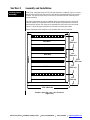
Most Sixnet components snap onto DIN rail strips fastened to a subpanel. Figure 2-1 shows a
sample panel with DIN rail strips and wire duct attached. Recommended DIN rail spacing is
8 inches. This spacing allows room for wire duct to be installed without obstructing field
wiring installation.
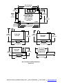
The Sixnet components are typically installed against one another, but space may be left
between modules to accommodate other DIN rail mounted components such as terminal
blocks and fuse holders. End clamps are recommended to restrict side-to-side movement.
Figure 2-2 shows the physical dimensions of the units covered by this manual.
Sixnet components can be installed in any orientation and order on your panel.
Sample Layout For a 36” x 30” Enclosure
(Figure 2-1)
Wire Duct
Wire Duct
Wire Duct
Wire Duct
Wire Duct
Wire Duct
27.0" (68.6 cm)
33.0"
(83.8 cm)
8.0"
(20.3 cm)
6.5"
(16.5 cm)
8.0"
(20.3 cm)
8.0"
(20.3 cm)

Red Lion Controls 20 Willow Springs Circle York, PA 17406 USA 1.717.767.6511 [email protected]
IPm Controllers and RTU Dimensions
(Figure 2-2)
0.25"
[0.64 cm]
2.92"
[7.42 cm]
0.17"
[0.43]
(clear for
#8 screw)
DIN EN
50022
(not
included)
4.47" [11.35 cm]
4.75" [12.07 cm]
3.17" [8.05 cm]
1.85"
[4.70 cm]
1.65"
[4.19 cm]
SixTRAK IPm,
VersaTRAK IPm,
and SixTRAK
I/O Controller
Front View
ST-GT SIXNET
ST-GT-####
Side View
3.00"
[7.63 cm]
3.17" [8.05 cm]
2.55"
[6.48 cm]
ST-IPM-####
Side View
2.49"
[6.33 cm]
3.17" [8.05 cm]
2.04"
[5.19 cm]
VT-IPM-####
Side View
4.27" [10.83 cm]
4.47" [11.35 cm]
2.92"
[7.42 cm]
3.17"
[8.05 cm]
4.27" [10.83 cm]
1.38" [3.5 cm]
1.06" [2.7 cm]
0.30" [0.76 cm]
DIN EN50022
(not included with units)
(not shown to scale)
(for reference only)

Red Lion Controls 20 Willow Springs Circle York, PA 17406 USA 1.717.767.6511 [email protected]
Section 3
Power and ST-Bus Wiring
Power
Requirements
Sixnet IPm controllers and RTU accept 24 VDC power from a Sixnet power supply (ST-PS-
024-02N or RM-PS-024-01F) or from a user DC power source of 10 to 30 VDC.
ST-PS-024-02N
(24VDC @ 2A)
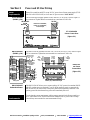
The SixTRAK power supply operates on 90 to 260VAC (47 to 63 Hz.). Refer to Figure 3-1
for connections. Tighten these screw terminals to a maximum of 3.48 in-lbs.
ST-PS-024-02N
Power Connections
(Figure 3-1)
RM-PS-024-01F
(24VDC @ 1A)
The RM-PS-024-01F operates on 85-264 VAC (47-63 Hz) or 120-370 VDC. Refer to Figure
3-2 for connections. Tighten the screw terminals to a maximum of 3.48 in-lbs.
RM-PS-024-
01F Power
Connections
(Figure 3-2)
RM-PS-024-01F
Redundant Power
The RM-PS-024-01F allows you to connect auxiliary 24 VDC power (from another RM-PS-
024-01F or other source) to terminals 17 and 18. When auxiliary power is connected, the
RM-PS-024-01F will source most of the power, under normal operating conditions. If the
primary power fails then the auxiliary power will immediately take over.
Current
Requirements
To calculate the current requirements, add the wattage required for the Sixnet controller or
RTU, and modules in use. Then divide the total wattage by the DC power source voltage.
Then add any current needed for user instrumentation loops.
90-260 VAC
Power for controllers,
RTUs, I/O, expanders,
or user loops
Line
Neutral
+
+
-
-
-
-
24 VDC
Line
Line
Neutral
Neutral
Chassis GND
DC +
DC +
DC --
DC --
Chassis GND
Optional
Auxiliary
DC Input
AC
Power
Input
DC
Power
Output
DC Power for controllers,
RTUs, I/O, and user loops
Optional Auxiliary
DC Power Input
GND DC+
Extra terminals
for 4-20 loops,
fields devices
and more
DC GND
DC + IN
DC GND
DC GND
DC GND
DC GND
DC GND
DC GND
DC GND
DC GND
DC+ OUT
DC+ OUT
DC+ OUT
DC+ OUT
DC+ OUT
DC+ OUT
DC+ OUT
DC+ OUT
Chassis
DC GND
DC GND
DC+ OUT
DC+ OUT
DC GND
DC+ IN
Line
Line
Neutral
Neutral
Chassis
4-20
Input
Field
Device
Discrete
Output
Discrete
Input
Wiring Base
Opt. Auxiliary
Power Input

Red Lion Controls 20 Willow Springs Circle York, PA 17406 USA 1.717.767.6511 [email protected]
DC Power Wiring
All Sixnet units and user instrumentation loops may be powered from a single DC source.
Refer to Figure 3-3 and 3-4 for typical DC power connections. The user DC power source
must be between 10 to 30 volts.
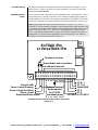
Redundant Power
Inputs
The SixTRAK IPm and VersaTRAK IPm have redundant power + input terminals. (There is
one common power – terminal.) This allows you to connect two separate power supplies. If
one fails then the other will take over powering your hardware. The SixTRAK I/O Controller
can also have redundant power inputs but requires an externally wired diode. See figure 3-4.
Note: In the SixTRAK IPm and VersaTRAK IPm, the ST C (+) and ST D (-) of the
SixTRAK ST-BUS are internally connected to only the primary power input (terminals 2 and
4). Therefore, when running on only auxiliary power (terminals 3 and 4) then there will be no
power on terminals 16 and 17 (ST C and ST D). If redundant power is desired for the ST-
BUS it is recommended that the auxiliary power + be connected to terminal 16 through an
external diode. The diode should be appropriately sized (current rating) for the number of
SixTRAK I/O modules being powered. See figure 3-3.
SixTRAK IPm and VersaTRAK IPm Power Connections
(Figure 3-3)
or VersaTRAK IPm
SixTRAK IPm
1 2
3
4
5
6
7
8 9 10
11 12
13
14
15 16
17
SixTRAK I/O (ST-BUS)
ST D (-)
ST C (+)
Shield GND
ST B
ST A
Chassis GND
Power + Input (Primary)
Power + Input (Auxiliary)
Power - Input
Redundant Power Inputs
To internal circuitry
Optional external
diode required
for ST-BUS
redundant power
These diodes and connections
are internal to the unit.

Red Lion Controls 20 Willow Springs Circle York, PA 17406 USA 1.717.767.6511 [email protected]
ST-Bus Wiring
Guidelines
ST-Bus wiring connects the SixTRAK I/O modules and expanders to the controller or RTU.
Follow the upcoming guidelines for reliable performance.
ST-Bus
Capability
Max. modules controlled by one controller or RTU ........................................................ 128
Max. modules or expanders connected directly to controller or RTU ............... 20 (any mix)
Max. modules connected to expander output .................................................... 20 (any mix)
Required cable type ........................... Any with 2 individually shielded pairs, 22AWG min.
Recommended cables .......................................... Alpha 2466C, Belden 8723, Carol C1352
Max. cabling off each controller, RTU or expander ........................................... 50 ft. (16M)
ST-EX-001-20U
I/O Expander
See the SixTRAK I/O User manual for details on using the ST-EX-001-20U I/O expander.

Red Lion Controls 20 Willow Springs Circle York, PA 17406 USA 1.717.767.6511 [email protected]
Connect up to 20 I/O modules or expanders directly to the
controller or RTU with a maximum total cabling of 50 feet.
Likewise, connect up to 20 I/O modules to each expander.
All expanders must be connected directly to the controller or
RTU. (Expanders cannot be cascaded in series.)
ST-Bus connections may form star configurations without
any restrictions.
Route ST-Bus wiring away from power wiring and sources of
electrical interference.
Expanders may be used in cabinets with more than 20 I/O modules as long as the total length of wire
stays within the 50-foot limit. Extending ST-Bus wiring to additional cabinets is not recommended.
Instead, use a gateway, RTU or I/O concentrator in each additional cabinet and run Ethernet, RS232 or
RS485 wiring between the cabinets.
Use the supplied ST-Bus jumpers between adjacent SixTRAK components. Otherwise, use the recommended cable.
I/O
Maximum cabling (total combined)
directly off RTU or Controller: 50 ft. (16m)
RTU or
Controller
I/O
I/O
I/O
I/O I/O
Maximum cabling (total combined)
off each Expander: 50 ft. (16m)
Expander
I/O
Expander
I/O
RTU or
Controller
Expander
Expander
I/O
I/O
I/O
I/O
I/O
I/O I/O
I/O
I/O
I/O
RTU or
Controller
I/O
I/O I/O
ST-BUS
Power & Control Wiring
Route
Separately
17 18 24 25 26 27 28
ST ST ST ST
A B C D
GND
19 20 21 22 23 17 18 24 25 26 27 28
ST ST ST ST
A B C D
GND
ST ST ST ST
A B C D
GND
ST ST ST ST
A B C D
GND
19 20 21 22 23 17 18
With adjacent SixTRAK I/O modules
use the supplied jumper wires
For distances up to 50 ft.
use the recommended cable
SixTRAK I/O module SixTRAK I/O moduleSixTRAK I/O module

Red Lion Controls 20 Willow Springs Circle York, PA 17406 USA 1.717.767.6511 [email protected]
Section 4
Communications
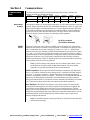
Communication
ports
The Sixnet controllers and RTUs covered by this manual have various combinations of
Ethernet and serial ports. See the chart below.
Product
RS232
Port A
RS232
Port B
RS485
Port C
RS232
Port D
Ethernet
Port 1
Ethernet
Port 2
Built-in
Switch
ST-IPM-####
X
X
X
-
X
X
X
VT-IPM-####
X
X
X
X
X
-
-
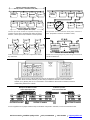
RS232 Ports
A and B
These ports are identical in connection and functionality. A RJ45 female connector is provided
for each. The pin-outs follow the EIA/TIA-561standard (See figures 4-1 and 4-2). A pre-wired
DB9F to RJ45F adapter is included with these units. Use this adapter along with a RJ45 male
to RJ45 male straight-thru wired patch cable (not included) to make a connection between a
com port on your PC (DB9 male) and either Port A or B (RJ45 female). Refer to the Sixnet
Electronic catalog for more information on connecting to other equipment.
RJ45 Pin Locations
(for RS232 or Ethernet)
RS485
Port C
This port is found on all units. It provides a RS485 (2-wire, half duplex only) connection to
Sixnet’s RemoteTRAK I/O modules or other equipment. Four terminals (for signal gnd, 485+,
485-, & termination) are provided. Generally, you connect + to + and – to – between units.
However, since there is no standard for RS485 terminal designations you may need to connect
+ to – and – to + in some cases. No damage will result if you connect incorrectly. It is highly
recommended that you tie the signal ground to an appropriate ground (if available) between all
RS485 units. Make sure to use a good quality communication cable with three conductors
(twisted is preferred) plus a shield. To prevent ground loops, the shield should be connected to
chassis ground on only one end of any cable run.
Note: If you have existing wiring that has only two conductors and a shield, you can
use the shield to connect the signal grounds between stations. This is not optimal
(especially for long cable runs) but should work in most situations.
RS485 Termination: All these units have RS485 termination components (150 ohm resistor
and a 0.1 F capacitor connected in series) already inside. To terminate your RS485 network
just tie the “T” terminal to the RS485 – terminal. Make sure to use the same type and size
conductor as used already used for your RS485 – connection. It is recommended that both end
stations of your RS485 network be terminated. Avoid terminating more than two stations.
Refer to the RemoteTRAK I/O User Manual on how to terminate a RemoteTRAK I/O Module.
For 3
rd
party devices, please refer to their user manual for termination instructions.
Bias Resistors: On a RS485 2-wire network, a pair of bias resistors (1K ohm typically)
acting upon the transmit/receive wires may be required. If bias resistors are not present, the
receive inputs on some RS485 devices may react to noise on the floating wires. The bias
resistors will force the transmit/receive wires to a known (non-floating) state when none of the
RS485 devices are transmitting data. Some RS485 devices have bias resistors built-in, and are
enabled through DIP-switch or jumper settings. Make sure there is only one pair of bias
resistors acting upon the network.
Note: If your RS485 network is made up exclusively of Sixnet devices then these bias
resistors are not necessary.

Red Lion Controls 20 Willow Springs Circle York, PA 17406 USA 1.717.767.6511 [email protected]
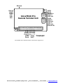
RS232
Port D
This port is found only on the VersaTRAK IPm. Five screw terminals (for TD, RD, RTS, CTS,
and GND) are provided to make your connections. Note: The 5
th
terminal is signal ground and
is shared by the adjacent RS485 Port C. Refer to figure 4-2 for the exact connections.
Ethernet Port 1
(Primary)
This port is found on all units. It is a 10/100BaseTx auto-detecting and auto-crossover Ethernet
port. This means it will auto-detect the speed, and work with either a straight-thru or cross-
wired Ethernet cable. A standard shielded RJ45 connector is provided. See the figures below
for the pin-outs. This port has a fixed unique MAC address. The IP address can be set with the
Sixnet I/O Tool Kit software. Refer to the on-line help for details.
Ethernet Port 2 with
Built-in Switch
This port is found on only the SixTRAK IPm. It is internally tied to an industrial Ethernet
switch (equivalent to Sixnet’s ET-GT-5ES-1). This provides four switched ports (standard
shielded RJ45 connectors) to connect to peripheral equipment such as Sixnet’s EtherTRAK
Ethernet I/O modules. All are 10/100BaseTx auto-detecting and auto-crossover Ethernet ports.
This means they will auto-detect the speed, and work with either a straight-thru or cross-wired
Ethernet cable. This port has a fixed unique MAC address. The IP address can be set with the
Sixnet I/O Tool Kit software. Refer to the on-line help for details.
Note: The primary Ethernet port is not internally tied to the internal Ethernet switch or the
second Ethernet port. The first and second Ethernet ports act independently from each other.
Refer to the Sixnet Electronic Help system for more details and usage tips.
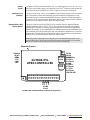
SixTRAK IPm Communication Connections (Figure 4-1)
OPEN CONTROLLER
SixTRAK IPm
1 2
3
4
5 6
7
8 9 10
11 12
13
14
15 16
17
RS232
(RJ45)
1 RI/DSR in
2 DCD in
3 DTR out
4 GND
5 RXD in
6 TXD out
7 CTS in
8 RTS out
(EIA/TIA-561)
G + - T
RS485
Port C
Ethernet
(RJ45)
1 TX+
2 TX-
3 RX+
6 RX-
Ethernet (5 ports)
RS232
Port A
RS232
Port B

Red Lion Controls 20 Willow Springs Circle York, PA 17406 USA 1.717.767.6511 [email protected]
VersaTRAK IPm Communication Connections (Figure 4-2)
Remote Terminal Unit
VersaTRAK IPm
1 2
3
4
5
6
7
8 9 10
11 12
13
14
15 16
17
RS232
(RJ45)
1 RI/DSR in
2 DCD in
3 DTR out
4 GND
5 RXD in
6 TXD out
7 CTS in
8 RTS out
(EIA/TIA-561)
G + - T
RS485
Port C
TD
RD
RTS
CTS
Ethernet
(RJ45)
1 TX+
2 TX-
3 RX+
6 RX-
Ethernet
RS232
Port A
RS232
Port B
RS232
Port D
(These ports share
a common GND.)

Red Lion Controls 20 Willow Springs Circle York, PA 17406 USA 1.717.767.6511 [email protected]
Section 5
Technical Specifications
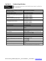
Technical
Specifications
Here are the technical specifications for the SixTRAK IPm Open Controller, VersaTRAK IPm
RTU, and SixTRAK I/O.
General
Industrial PowerPC (32 bit data bus)
Compatibility with legacy VersaTRAK RTU and SixTRAK
Programmable I/O Gateway
Fully (except there is no on-board I/O)
Operating system
Embedded LINUX
Unique station addresses (unit Ids)
16,000+ (Sixnet) or 247 (Modbus)
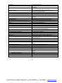
Dynamic memory (RAM)
(for program execution, dynamic variables, dynamic file
system, etc.)
32bit, 0 wait states
xT-IPM-1### 16 Megabytes
xT-IPM-2### 16 Megabytes
xT-IPM-6### 64 Megabytes
Program memory (Flash)
(for Linux OS, program storage, and file system)
xT-IPM-1### 16 Megabytes
xT-IPM-2### 16 Megabytes
xT-IPM-6### 16 Megabytes
Additional Flash memory
xT-IPM-6### 128 Megabytes
Datalogging memory (RAM)
(for datalogging and retained variables)
Battery-backed – Rechargeable Lithium
xT-IPM-1### 512K bytes
xT-IPM-2### 2 Megabytes
xT-IPM-6### 2 Megabytes
Battery-backup time / life
1 year / 10+ years
Real-time clock resolution
10 mS
Real-time clock accuracy
+/-15 seconds per month
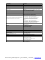
I/O expansion
SixTRAK, EtherTRAK, RemoteTRAK
Maximum local I/O (via ST-Bus port)
1,024 (128 SixTRAK modules) (expander required after every 20
modules)
Maximum distributed I/O (application dependent)
50,000+
Datalogging support
Yes – Sixnet Sixlog
Datalogging modes
Trending, alarm logging, sequence of events, event initiated, client
transfers, and others
LINUX capabilities
Practically unlimited (standard option for ST-IPm and VT-IPm)
(OEM only option for ST-GT-####)
Programming
High level C and others
Number of applications allowed
As many as there is memory for
Available FREE source code
Practically unlimited
IEC 61131 PLCopen programming
Yes – Sixnet ISaGRAF
Languages supported
Ladder logic, function chart, function block, instruction list,
structured text, and flow chart
Number of programs allowed to be run in IPm at same
time
1 for ST-GT-####
2 for VT-IPM-####
4 for ST-IPM-####
Cycle time
10 mS minimum (user settable)
Communication capabilities
Master, slave, peer to peer, report on exception, store and forward
and more
Communication media supported
Ethernet, telemetry, telephone (dialup and leased line), radio (dumb
and smart), other wireless, fiber optic, short haul and more

Red Lion Controls 20 Willow Springs Circle York, PA 17406 USA 1.717.767.6511 [email protected]
Redundancy
Various levels supported
Redundant Ethernet links (ST-IPm only)
Yes – 2 unique MAC & IP addresses allow for 2 unique network
connections
Redundant I/O modules
Yes – multiple modules can interface to the same I/O; an internal
discrete bit reports on-line status of each module
Redundant controllers
Yes – automatic controller switch-over is supported (user
application programming required)
Redundant power inputs (ST-IPM and VT-IPM only)
Yes – automatic switch-over on failure
Backup RS485 communications
Yes – especially with EtherTRAK modules
Watchdogs and Monitors
For run-time diagnostics
CPU watchdog
CPU automatically resets if error is detected; status LED flashes
error code
Communications watchdog
Settable timeout and output action (force off or freeze)
Heartbeat watchdog
Settable timeout & output action (force off or freeze)
Ethernet Port(s)
10/100BaseTx (auto-detecting)
Connection
RJ45 (auto-crossover)
Isolation
1500 Volts RMS 1 minute (60 Hz.)
Message response time (typical)
5 mS
Diagnostic LEDs on each port
Indicates speed, link and activity
Protocols supported
TCP/IP, ARP, UDP, ICMP, DHCP, Modbus/TCP, Sixnet, and more
Independent networks
VT-IPm & ST-GT = 1 w/ unique MAC & IP address
ST-IPm = 2 w/ unique MAC & IP addresses
Network port 1
1 shielded RJ45 connector
Network port 2 (ST-IPm only)
4 shielded RJ45 connectors (linked via integrated Ethernet switch)
Integrated Ethernet switch features
Same as Sixnet’s ET-GT-5ES-1
Serial Ports
300 to 115,200 baud
RS232 Port A
RJ45 (TD, RD, CTS, RTS, CD, DTR, DSR/RI , GND)
RS232 Port B
RJ45 (TD, RD, CTS, RTS, CD, DTR, DSR/RI , GND)
RS485 Port C
Screws (GND, 485+, 485-, termination) (2-wire half-duplex) (GND
common with port D)
RS485 network
Up to 32 (full-load) stations
RS485 distance
Up to 0.5 miles (1 km)
RS232 Port D (VT-IPm only)
Screws (TD, RD, RTS, CTS, GND)
Protocols (master & slave)
Sixnet & Modbus (RTU and ASCII); Many others available in
LINUX
Diagnostic LEDs on each port
Transmit Data (TD) & Receive Data (RD)
Flow Control
Hardware, software, RTS-party (for radios and RS485)
ST-BUS (local I/O) port
Full line of analog and discrete I/O
Modules
Up to 128 (including expanders)
I/O channels
Up to 1,024
Scan time
5 mS minimum (varies depending on quantity and type of I/O
modules)
Benchmark 1: 48 discretes & 8 analog
10 mS
Benchmark 2: 512 discretes
30 mS
Benchmark 3: 128 analogs
40 mS
Benchmark 3: 512 discretes & 128 analogs
80 mS
La page est en cours de chargement...
La page est en cours de chargement...
La page est en cours de chargement...
-
 1
1
-
 2
2
-
 3
3
-
 4
4
-
 5
5
-
 6
6
-
 7
7
-
 8
8
-
 9
9
-
 10
10
-
 11
11
-
 12
12
-
 13
13
-
 14
14
-
 15
15
-
 16
16
-
 17
17
-
 18
18
-
 19
19
-
 20
20
-
 21
21
-
 22
22
-
 23
23


dans d''autres langues
- English: Sixnet IPm Installation guide
Documents connexes
Autres documents
-
red lion ST Manuel utilisateur
-
-
-
Alarm Lock Trilogy Networx AL-IME2-PIE Installation Instructions Manual
-
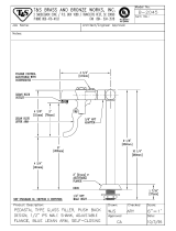 T & S Brass & Bronze Works B-2045 Fiche technique
-
-
red lion RAM-99x1 Series Manuel utilisateur
-
-
red lion E3 Guide de démarrage rapide
-
Allworx Tx 92/24 Guide d'installation
