Hikoki WR36DE Manuel utilisateur
- Catégorie
- Clés à chocs électriques
- Taper
- Manuel utilisateur

Designed for operating in USA & Canada only.
When this product is used in areas other than the USA & Canada,
we cannot guarantee the product quality and performance.
SAFETY INSTRUCTIONS AND INSTRUCTION MANUAL
WARNING
IMPROPER OR UNSAFE use of this power tool can result in death or serious bodily injury!
This manual contains important information about product safety. Please read and understand
this manual BEFORE operating the power tool. Please keep this manual available for other
users and owners before they use the power tool. This manual should be stored in safe place.
INSTRUCTIONS DE SECURITE ET MODE D’EMPLOI
AVERTISSEMENT
Une utilisation INCORRECTE OU DANGEREUSE de cet outil motorisé peut entraîner la mort
ou de sérieuses blessures corporelles!
Ce mode d’emploi contient d’importantes informations à propos de la sécurité de ce produit.
Prière de lire et de comprendre ce mode d’emploi AVANT d’utiliser l’outil motorisé. Garder ce
mode d’emploi à la disponibilité des autres utilisateurs et propriétaires avant qu’ils utilisent
l’outil motorisé. Ce mode d’emploi doit être conservé dans un endroit sûr.
INSTRUCCIONES DE SEGURIDAD Y MANUAL DE INSTRUCCIONES
ADVERTENCIA
¡La utilización INAPROPIADA O PELIGROSA de esta herramienta eléctrica puede resultar
en lesiones de gravedad o la muerte!
Este manual contiene información importante sobre la seguridad del producto. Lea y
comprenda este manual ANTES de utilizar la herramienta eléctrica. Guarde este manual para
que puedan leerlo otras personas antes de utilizar la herramienta eléctrica. Este manual debe
ser guardado en un lugar seguro.
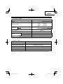
Model
Modèle
Modelo WR 36DE
Cordless Impact Wrench
Clé à choc sans fi l
Llave de impacto a batería

IMPORTANT SAFETY INSTRUCTIONS
Read and understand all of the safety precautions, warnings and operating instructions in the Instruction Manual before
operating or maintaining this power tool.
Most accidents that result from power tool operation and maintenance are caused by the failure to observe basic safety
rules or precautions. An accident can often be avoided by recognizing a potentially hazardous situation before it occurs,
and by observing appropriate safety procedures.
Basic safety precautions are outlined in the “SAFETY” section of this Instruction Manual and in the sections which
contain the operation and maintenance instructions.
Hazards that must be avoided to prevent bodily injury or machine damage are identifi ed by WARNINGS on the power
tool and in this Instruction Manual.
NEVER use this power tool in a manner that has not been specifi cally recommended by metabo HPT.
MEANINGS OF SIGNAL WORDS
WARNING indicates a potentially hazardous situations which, if ignored, could result in death or serious injury.
CAUTION indicates a potentially hazardous situations which, if not avoided, may result in minor or moderate injury, or
may cause machine damage.
NOTE emphasizes essential information.
SAFETY
GENERAL POWER TOOL SAFETY WARNINGS
WARNING
Read all safety warnings and all instructions.
Failure to follow the warnings and instructions may result in electric shock, fi re and/or serious injury.
Save all warnings and instructions for future reference.
The term “power tool” in the warnings refers to your mains-operated (corded) power tool or battery-operated
(cordless) power tool.
1) Work area safety
a) Keep work area clean and well lit.
Cluttered or dark areas invite accidents.
b) Do not operate power tools in explosive
atmospheres, such as in the presence of
fl ammable liquids, gases or dust.
Power tools create sparks which may ignite the
dust or fumes.
c) Keep children and bystanders away while
operating a power tool.
Distractions can cause you to lose control.
2) Electrical safety
a) Power tool plugs must match the outlet.
Never modify the plug in any way.
Do not use any adapter plugs with earthed
(grounded) power tools.
Unmodifi ed plugs and matching outlets will reduce
risk of electric shock.
b) Avoid body contact with earthed or grounded
surfaces such as pipes, radiators, ranges and
refrigerators.
There is an increased risk of electric shock if your
body is earthed or grounded.
c) Do not expose power tools to rain or wet
conditions.
Water entering a power tool will increase the risk
of electric shock.
d) Do not abuse the cord. Never use the cord
for carrying, pulling or unplugging the power
tool.
Keep cord away from heat, oil, sharp edges or
moving parts.
Damaged or entangled cords increase the risk of
electric shock.
e) When operating a power tool outdoors, use
an extension cord suitable for outdoor use.
Use of a cord suitable for outdoor use reduces the
risk of electric shock.
f) If operating a power tool in a damp location
is unavoidable, use a residual current device
(RCD) protected supply.
Use of an RCD reduces the risk of electric shock.
2
English

3) Personal safety
a) Stay alert, watch what you are doing and use
common sense when operating a power tool.
Do not use a power tool while you are tired
or under the infl uence of drugs, alcohol or
medication.
A moment of inattention while operating power
tools may result in serious personal injury.
b) Use personal protective equipment. Always
wear eye protection.
Protective equipment such as dust mask, non-skid
safety shoes, hard hat, or hearing protection used
for appropriate conditions will reduce personal
injuries.
c) Prevent unintentional starting. Ensure the
switch is in the off -position before connecting
to power source and/or battery pack, picking
up or carrying the tool.
Carrying power tools with your fi nger on the switch
or energising power tools that have the switch on
invites accidents.
d) Remove any adjusting key or wrench before
turning the power tool on.
A wrench or a key left attached to a rotating part of
the power tool may result in personal injury.
e) Do not overreach. Keep proper footing and
balance at all times.
This enables better control of the power tool in
unexpected situations.
f) Dress properly. Do not wear loose clothing or
jewellery. Keep your hair, clothing and gloves
away from moving parts.
Loose clothes, jewellery or long hair can be caught
in moving parts.
g) If devices are provided for the connection
of dust extraction and collection facilities,
ensure these are connected and properly
used.
Use of dust collection can reduce dust-related
hazards.
4) Power tool use and care
a) Do not force the power tool. Use the correct
power tool for your application.
The correct power tool will do the job better and
safer at the rate for which it was designed.
b) Do not use the power tool if the switch does
not turn it on and off .
Any power tool that cannot be controlled with the
switch is dangerous and must be repaired.
c) Disconnect the plug from the power source
and/or the battery pack from the power tool
before making any adjustments, changing
accessories, or storing power tools.
Such preventive safety measures reduce the risk
of starting the power tool accidentally.
d) Store idle power tools out of the reach of
children and do not allow persons unfamiliar
with the power tool or these instructions to
operate the power tool.
Power tools are dangerous in the hands of
untrained users.
e) Maintain power tools. Check for misalignment
or binding of moving parts, breakage of parts
and any other condition that may aff ect the
power tool’s operation.
If damaged, have the power tool repaired
before use.
Many accidents are caused by poorly maintained
power tools.
f) Keep cutting tools sharp and clean.
Properly maintained cutting tools with sharp
cutting edges are less likely to bind and are easier
to control.
g) Use the power tool, accessories and tool bits
etc. in accordance with these instructions,
taking into account the working conditions
and the work to be performed.
Use of the power tool for operations diff erent
from those intended could result in a hazardous
situation.
5) Battery tool use and care
a) Recharge only with the charger specifi ed by
the manufacturer.
A charger that is suitable for one type of battery
pack may create a risk of fi re when used with
another battery pack.
b) Use power tools only with specifi cally
designated battery packs.
Use of any other battery packs may create a risk of
injury and fi re.
c) When battery pack is not in use, keep it away
from other metal objects like paper clips,
coins, keys, nails, screws, or other small
metal objects, that can make a connection
from one terminal to another.
Shorting the battery terminals together may cause
burns or a fi re.
d) Under abusive conditions, liquid may be
ejected from the battery; avoid contact. If
contact accidentally occurs, fl ush with water.
If liquid contacts eyes, additionally seek
medical help.
Liquid ejected from the battery may cause irritation
or burns.
6) Service
a) Have your power tool serviced by a
qualifi ed repair person using only identical
replacement parts.
This will ensure that the safety of the power tool is
maintained.
3
English

12. Do not use power tools if the plastic housing or
handle is cracked.
Cracks in the tool’s housing or handle can lead to
electric shock. Such tools should not be used until
repaired.
13. Blades and accessories must be securely
mounted to the tool.
Prevent potential injuries to yourself or others. Blades,
cutting implements and accessories which have been
mounted to the tool should be secure and tight.
14. NEVER use a tool which is defective or operating
abnormally.
If the tool appears to be operating unusually, making
strange noises, or otherwise appears defective, stop
using it immediately and arrange for repairs by a
metabo HPT authorized service center.
15. Carefully handle power tools.
Should a power tool be dropped or struck against
hard materials inadvertently, it may be deformed,
cracked, or damaged.
16. Do not wipe plastic parts with solvent.
Solvents such as gasoline, thinner benzine, carbon
tetrachloride, and alcohol may damage and crack
plastic parts. Do not wipe them with such solvents.
Wipe plastic parts with a soft cloth lightly dampened
with soapy water and dry thoroughly.
17. Always wear eye protection that meets the
requirement of the latest revision of ANSI
Standard Z87.1.
18. Do not use the product if the tool or the battery
terminals (battery mount) are deformed.
Installing the battery could cause a short circuit that
could result in smoke emission or ignition.
19. Keep the tool’s terminals (battery mount) free of swarf
and dust.
○
Prior to use, make sure that swarf and dust have not
collected in the area of the terminals.
○
During use, try to avoid swarf or dust on the tool from
falling on the battery.
○
When suspending operation or after use, do not leave
the tool in an area where it may be exposed to falling
swarf or dust.
Doing so could cause a short circuit that could result
in smoke emission or ignition.
20. Defi nitions for symbols used on this tool
V ............ volts
—
---
......... direct current
no .......... no load speed
---/min .... revolutions or reciprocation per minute
– WARNING –
To reduce the risk of injury, user must read
instruction manual.
SPECIFIC SAFETY RULES AND SYMBOLS
1. Hold power tools by insulated gripping surfaces,
when performing an operation where the
fastener may contact hidden wiring.
Fasteners contacting a “live” wire may make exposed
metal parts of the power tool “live” and could give the
operator an electric shock.
2. ALWAYS wear ear protectors when using the tool
for extended periods.
Prolonged exposure to high intensity
noise can cause hearing loss.
3. NEVER place hands or other body parts near the drill
bit or chuck during operation. Hold the impact wrench
by its handle only.
4. Because the cordless impact wrench operates by
battery power, be aware of the fact that it can begin to
operate at any time.
5. When working at elevated locations, clear the area
of all other people and be aware of conditions below
you.
6. NEVER touch moving parts.
NEVER place your hands, fi ngers or other body parts
near the tool’s moving parts.
7. NEVER operate without all guards in place.
NEVER operate this tool without all guards or safety
features in place and in proper working order. If
maintenance or servicing requires the removal of a
guard or safety feature, be sure to replace the guard or
safety feature before resuming operation of the tool.
8. Use right tool.
Don’t force small tool or attachment to do the job of a
heavy-duty tool.
Don’t use tool for purpose not intended —for
example— don’t use circular saw for cutting tree
limbs or logs.
9. NEVER use a power tool for applications other
than those specifi ed.
NEVER use a power tool for applications other than
those specifi ed in the Instruction Manual.
10. Handle tool correctly.
Operate the tool according to the instructions provided
herein. Do not drop or throw the tool. NEVER allow the
tool to be operated by children, individuals unfamiliar
with its operation or unauthorized personnel.
11. Keep all screws, bolts and covers tightly in place.
Keep all screws, bolts, and plates tightly mounted.
Check their condition periodically.
4
English

IMPORTANT SAFETY INSTRUCTIONS
FOR USE OF THE CORDLESS IMPACT
WRENCH
WARNING
Death or serious bodily injury could result from
improper or unsafe use of the cordless impact
wrench. To avoid these risks, follow these basic
safety instructions:
1. Never use this impact wrench handle for any
application other than those in this manual.
2. When working in high places, always make sure that
ther is no one below before starting to work.
3. Always wear eye and ear protection when you work.
4. Confi rm whether the socket has any crack in it.
5. Attach the hex. socket securely onto the anvil. Be sure
to fasten the socket with the pin and O-ring before
use. If the hex. socket is insuffi ciently secured, it
may drop out and cause an accident. For hex. socket
attachment refer to “OPERATION”.
6. Confi rm the tightening torque by a torque wrench
before use in order to ascertain the correct tightening
torque to be used.
7. If a universal joint is used, be sure not to operate the
unit in a no-load condition. Operating in this condition
is dangerous. When the socket section spins around
it may cause injury to hands or bodies, or the resulting
intense vibration may cause the user to drop the tool.
IMPORTANT SAFETY INSTRUCTIONS
FOR BATTERY CHARGER
WARNING
Death or serious bodily injury could result from
improper or unsafe use of battery chargers.
To avoid these risks, follow these basic safety
instructions:
READ ALL INSTRUCTIONS
1. This manual contains important safety and operating
instructions for battery charger Model UC18YSL3.
2. Before using battery charger, read all instructions
and cautionary markings on (1) battery charger, (2)
battery, and (3) product using battery.
3. To reduce risk of injury, charge metabo HPT
rechargeable battery models of the multi volt series
and the BSL18 series. Other models of batteries may
burst causing personal injury and damage.
4. Use of an attachment not recommended or sold by
the battery charger manufacturer may result in a risk
of fi re, electric shock, or injury to persons.
5. To reduce risk of damage to electric plug and cord,
pull by plug when disconnecting battery charger.
6. Make sure cord is located so that it will not be stepped
on, tripped over, or otherwise subjected to damage or
stress.
7. An extension cord should not be used unless
absolutely necessary. Use of improper extension
cord could result in a risk of fi re and electric shock.
If extension cord must be used make sure:
a. That blades of extension cord are the same
number, size, and shape as those of plug on
battery charger:
b. That extension cord is properly wired and in good
electrical condition; and
c. That wire size is large enough for AC ampere
rating of battery charger as specifi ed in Table 1.
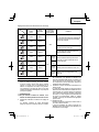
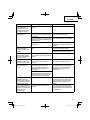
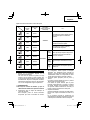
Table 1
RECOMMENDED MINIMUM AWG SIZE FOR
EXTENSION CORDS FOR BATTERY CHARGERS
AC Input Rating Amperes* AWG Size of Cord
Equal to or
greater than but less
than
Length of Cord, Feet (Meter)
25 (7.5) 50 (15) 100 (30) 150 (45)
0 2 18 18 18 16
2 3 18 18 16 14
3 4 18 18 16 14
5
English

7. NEVER connect two battery chargers together.
8. NEVER insert foreign objects into the hole for the
battery or the battery charger.
9. NEVER use a booster transformer when charging.
10. NEVER use DC power to charge.
11. NEVER store the battery or battery charger in places
where the temperature may reach or exceed 104°F
(40°C) such as inside metal box or car.
12. NEVER expose the battery or battery charger to rain
or wet conditions.
13. ALWAYS operate charger on standard household
electrical power (120 volts). Using the charger on any
other voltage may overheat and damage the charger.
14. ALWAYS wait at least 15 minutes between charges to
avoid overheating the charger.
15. ALWAYS disconnect the power cord from its
receptacle when the charger is not in use.
CAUTION ON LITHIUM-ION BATTERY
To extend the lifetime, the lithium-ion battery equips with
the protection function to stop the output.
In the cases of 1 to 3 described below, when using this
product, even if you are pulling the switch, the motor may
stop. This is not the trouble but the result of protection
function.
1. When the battery power remaining runs out, the motor
stops.
In such case, charge it up immediately.
2. If the tool is overloaded, the motor may stop. In this
case, release the switch of tool and eliminate causes
of overloading. After that, you can use it again.
3. If the battery is overheated under overload work, the
battery power may stop.
In this case, stop using the battery and let the battery
cool. After that, you can use it again.
Furthermore, please heed the following warning and
caution.
WARNING
In order to prevent any battery leakage, heat generation,
smoke emission, explosion and ignition beforehand,
please be sure to heed the following precautions.
1. Make sure that swarf and dust do not collect on the
battery.
○
During work make sure that swarf and dust do not fall
on the battery.
○
Make sure that any swarf and dust falling on the power
tool during work do not collect on the battery.
○
Do not store an unused battery in a location exposed
to swarf and dust.
○
Before storing a battery, remove any swarf and dust
that may adhere to it and do not store it together with
metal parts (screws, nails, etc.).
* If the input rating of a battery charger is given in watts
rather than in amperes, the corresponding ampere
rating is to be determined by dividing the wattage
rating by the voltage rating–for example:
1,250 watts = 10 amperes
125 volts
8. Do not operate battery charger with damaged cord or
plug-replace them immediately.
9. Do not operate battery charger if it has received a
sharp blow, been dropped, or otherwise damaged in
any way; take it to a qualifi ed serviceman.
10. Do not disassemble battery charger; take it to a
qualifi ed serviceman when service or repair is
required. Incorrect reassembly may result in a risk of
electric shock or fi re.
11. To reduce risk of electric shock, unplug charger from
receptacle before attempting any maintenance or
cleaning. Removing the battery will not reduce this
risk.
IMPORTANT SAFETY INSTRUCTIONS
FOR USE OF THE BATTERY AND
BATTERY CHARGER
You must charge the battery before you can use the power
tool. Before using the model UC18YSL3 battery charger,
be sure to read all instructions and cautionary statements
on it, the battery and in this manual.
CAUTION
USE ONLY metabo HPT BATTERY MODELS OF
THE MULTI VOLT SERIES. OTHER MODELS OF
BATTERIES MAY BURST AND CAUSE INJURY!
Follow these instructions to avoid the risk of injury:
WARNING
Improper use of the battery or battery charger
can lead to serious injury. To avoid these injuries:
1. NEVER disassemble the battery.
2. NEVER incinerate the battery, even if it is damaged or
is completely worn out. The battery can explode in a
fi re.
3. NEVER short-circuit the battery.
4. NEVER insert any objects into the battery charger’s
air vents. Electric shock or damage to the battery
charger may result.
5. NEVER charge outdoors. Keep the battery away
from direct sunlight and use only where there is low
humidity and good ventilation.
6. NEVER charge when the temperature is below 32°F
(0°C) or above 104°F (40°C).
6
English

2. Do not pierce battery with a sharp object such as a
nail, strike with a hammer, step on, throw or subject
the battery to severe physical shock.
3. Do not use an apparently damaged or deformed
battery.
4. Do not use the battery in reverse polarity.
5. Do not connect directly to an electrical outlets or car
cigarette lighter sockets.
6. Do not use the battery for a purpose other than those
specifi ed.
7. If the battery charging fails to complete even when a
specifi ed recharging time has elapsed, immediately
stop further recharging.
8. Do not put or subject the battery to high temperatures
or high pressure such as into a microwave oven,
dryer, or high pressure container.
9. Keep away from fi re immediately when leakage or foul
odor are detected.
10. Do not use in a location where strong static electricity
generates.
11. If there is battery leakage, foul odor, heat generated,
discolored or deformed, or in any way appears
abnormal during use, recharging or storage,
immediately remove it from the equipment or battery
charger, and stop use.
12. Do not immerse the battery or allow any fl uids to fl ow
inside. Conductive liquid ingress, such as water, can
cause damage resulting in fi re or explosion. Store your
battery in a cool, dry place, away from combustible
and fl ammable items. Corrosive gas atmospheres
must be avoided.
CAUTION
1. If liquid leaking from the battery gets into your eyes,
do not rub your eyes and wash them well with fresh
clean water such as tap water and contact a doctor
immediately.
If left untreated, the liquid may cause eye-problems.
2. If liquid leaks onto your skin or clothes, wash well with
clean water such as tap water immediately.
There is a possibility that this can cause skin irritation.
3. If you fi nd rust, foul odor, overheating, discolor,
deformation, and/or other irregularities when using
the battery for the fi rst time, do not use and return it to
your supplier or vendor.
WARNING
If an electrically conductive foreign object enters the
terminals of the lithium ion battery, a short-circuit may
occur resulting in the risk of fi re. Please observe the
following matters when storing the battery.
○
Do not place electrically conductive cuttings,
nails, steel wire, copper wire or other wire in the
storage case.
○
Either install the battery in the power tool or store
by securely pressing into the battery cover until
the ventilation holes are concealed to prevent
short-circuits (See Fig. 3).
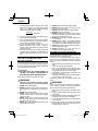
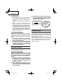
REGARDING LITHIUM-ION BATTERY
TRANSPORTATION
When transporting a lithium-ion battery, please observe
the following precautions.
WARNING
Notify the transporting company that a package
contains a lithium-ion battery, inform the company
of its power output and follow the instructions of the
transportation company when arranging transport.
●
Lithium-ion batteries that exceed a power output
of 100 Wh are considered to be in the freight
classifi cation of Dangerous Goods and will
require special application procedures.
●
For transportation abroad, you must comply with
international law and the rules and regulations of
the destination country.
●
If the BSL36B18 is installed in the power tool, the
power output will exceed 100 Wh and the unit
will be classifi ed as Dangerous Goods for freight
classifi cation.
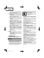
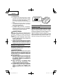
Wh
Power Output
2 to 3 digit number
Fig. 1
USB DEVICE CONNECTION
PRECAUTIONS
When an unexpected problem occurs, the data in a USB
device connected to this product may be corrupted or lost.
Always make sure to back up any data contained in the
USB device prior to use with this product.
Please be aware that our company accepts absolutely no
responsibility for any data stored in a USB device that is
corrupted or lost, nor for any damage that may occur to a
connected device.
7
English

PRECAUTIONS REGARDING THE DUST-RESISTANCE AND WATER-PROOFING
FUNCTIONS
This product conforms to IP56 protection class ratings (dust-resistance and water-proofi ng) for electrical equipment as
stipulated by the international IEC regulations. (Only the main unit conforms to the IP56 protection class ratings when
equipped with a battery.)
[Descriptions of IP Codes]
IP56 Protection rating for water penetration
Must be no adverse eff ects on the equipment when sprayed with powerful jets of water from all directions
(water-proofed).
(100 L of water per minute sprayed for approximately three minutes from a distance of approximately three
meters with the use of a spray nozzle with a diameter of 12.5 mm.)
Protection rating for external assault by solid objects
Dust that may cause adverse eff ects on the equipment must not be able to enter (dust-resistance).
(The equipment to be left non-operable in a test chamber in which particles of talcum powder with a diameter
of less than 75 μm are fl oating in the air with the use of an agitation pump at a rate of 2 kg per cubic meter for
eight hours.)
The equipment has been designed to withstand the eff ects of dust and water, but there is no guarantee that it will not
malfunction. Do not use or leave the equipment in locations where it is subject to excessive amounts of dust, or in
locations where it is submerged in water or subject to rainwater.
SAVE THESE INSTRUCTIONS
AND
MAKE THEM AVAILABLE TO OTHER USERS
AND
OWNERS OF THIS TOOL!
8
English

FUNCTIONAL DESCRIPTION
NOTE
The information contained in this Instruction Manual is designed to assist you in the safe operation and maintenance
of the power tool.
NEVER operate, or attempt any maintenance on the tool unless you have fi rst read and understood all safety
instructions contained in this manual.
Some illustrations in this Instruction Manual may show details or attachments that diff er from those on your own
power tool.
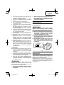
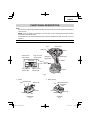
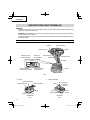
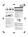
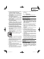
NAME OF PARTS
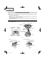
1. Cordless Impact Wrench
Push button
Battery
Motor
Switch panel Handle
Hook
High / Low mode
selector switch
Auto stop mode
selector switch
Auto stop mode
indicator lamp
Anvil Hammer case
Trigger switch
LED-Light
Friction ring
High / Low mode
indicator lamp
Fig. 2
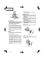
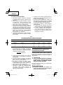
2. Battery 3. Battery Charger
Display panel
Battery
Ventilation holes
Terminals
Battery cover
Latch
Ventilation
holes
Body
Cord
Nameplate
Charge indicator lamp
Guide rail
<BSL36A18X>
Fig. 3
<UC18YSL3>
Fig. 4
9
English

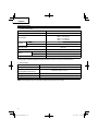
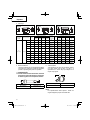
SPECIFICATIONS
1. Cordless Impact Wrench
Model WR36DE
Motor DC brushless motor
No-load speed
Mode 4 0–2,400 /min
Mode 3 0–2,100 /min
Mode 2 0–1,800 /min
Mode 1 0–1,500 /min
Capacity Ordinary bolt 3/8" (M10)–1" (M24)
High tension bolt 3/8" (M10)–3/4" (M20)
Tightening torque Maximum 568 ft-lbs
{770 N∙m}
Square Drive 1/2" (12.7 mm)
Battery* Type* Li-ion battery Model BSL36A18X
Voltage DC 36 V / 18 V
Weight 6.0 lbs. (2.7 kg)
* Existing batteries (BSL3660/3626/3620, BSL18xx and BSL14xx series, etc.) cannot be used with this tool.
2. Battery Charger
Model UC18YSL3
Input power source Single phase: AC 120 V 60 Hz
Charging time
(At a temperature of 68°F (20°C)) BSL36A18X : Approx. 32 min
Charging voltage DC 14.4–18 V
Charging current DC 8.0 A
Weight 1.3 lbs. (0.6 kg)
NOTE: The charging time may vary according to temperature and power source voltage.
10
English

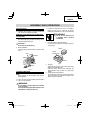
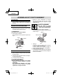
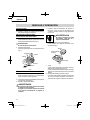
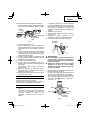
ASSEMBLY AND OPERATION
1. Connect the charger’s power cord to a receptacle.
When the power cord is connected, the charge
indicator lamp will blink in red. (At 1-second intervals)
WARNING
Do not use the electrical cord
if damaged. Have it repaired
immediately.
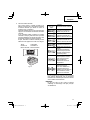
2. Insert the battery to the battery charger.
Firmly Insert the battery into the battery charger as
shown in Fig. 6.
Charge
indicator lamp
Guide rail
Battery
Fig. 6
3. Charging
When inserting a battery in the charger, the charge
indicator lamp will blink in blue.
When the battery becomes fully recharged, the
charge indicator lamp will light up in green.(See
Table 2)
(1) Charge indicator lamp indication
The indications of the charge indicator lamp will be
as shown in Table 2, according to the condition of the
battery charger or the battery.
APPLICATIONS
○
Tightening and loosening of all types of bolts and
nuts, used for securing structural items
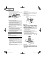
REMOVAL AND INSTALLATION METHOD
OF BATTERY
1. Battery removal
Hold the handle tightly and push the battery latch to
remove the battery (see Fig. 5).
CAUTION
Never short-circuit the battery.
2. Battery installation
Insert the battery while observing its polarities (see
Fig. 5).
Battery
Pull out
Insert
Handle
Latch
Push
Fig. 5
CHARGING METHOD
NOTE
Before plugging into the receptacle, make sure the
following points.
○
The power source voltage is stated on the nameplate.
○
The cord is not damaged.
WARNING
Do not charge at voltage higher than indicated
on the nameplate.
If charged at voltage higher than indicated on the
nameplate, the charger will burn out.
11
English

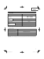
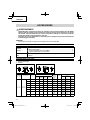
Table 2
Indications of the charge indicator lamp
Charge
indicator
lamp
(RED /
BLUE /
GREEN /
PURPLE)
Before
charging Blinks
(RED)
Lights for 0.5 seconds. Does not light
for 0.5 seconds.
(off for 0.5 seconds) Plugged into power source
While
charging
Blinks
(BLUE)
Lights for 0.5 seconds. Does not light
for 1 second.
(off for 1 second) Battery capacity at less than
50%
Blinks
(BLUE)
Lights for 1 second. Does not light for
0.5 seconds.
(off for 0.5 seconds) Battery capacity at less than
80%
Lights
(BLUE) Lights continuously Battery capacity at more than
80%
Charging
complete Lights
(GREEN)
Lights continuously
(Continuous buzzer sound: about
6 seconds)
Overheat
standby Blinks
(RED)
Lights for 0.3 seconds. Does not light
for 0.3 seconds.
(off for 0.3 seconds)
Battery overheated. Unable
to charge. (Charging will
commence when battery cools)
Charging
impossible Flickers
(PURPLE)
Lights for 0.1 seconds. Does not light
for 0.1 seconds.
(off for 0.1 seconds)
(Intermittent buzzer sound: about
2 seconds)
Malfunction in the battery or the
charger
NOTE
The recharging time may vary according to the
ambient temperature.
4. Disconnect battery charger from the receptacle.
CAUTION
Do not pull the plug out of the receptacle by
pulling on the cord.
Make sure to grasp the plug when removing from
receptacle to avoid damaging cord.
5. Remove the battery from the battery charger.
Supporting the battery charger with hand, pull out the
battery from the battery charger.
NOTE
Be sure to pull out the battery from the battery charger
after use, and then keep it.
(2) Regarding the temperature of the rechargeable
battery.
The temperatures for rechargeable batteries are
as shown in the Table 3, and batteries that have
become hot should be cooled for a while before being
recharged.
Table 3
Rechargeable
batteries Temperatures at which the battery
can be recharged
BSL36A18X 32°F–122°F
(0°C–50°C)
(3) Regarding recharging time (At 68°F (20°C))
Table 4 Charging time
Charger
Battery UC18YSL3
BSL36A18X Approx. 32 min
12
English

Regarding electric discharge in case of new
batteries, etc.
As the internal chemical substance of new batteries
and batteries that have not been used for an extended
period is not activated, the electric discharge might
be low when using them the fi rst and second time.
This is a temporary phenomenon, and normal time
required for recharging will be restored by recharging
the batteries 2–3 times.
How to make the batteries perform longer
(1) Recharge the batteries before they become
completely exhausted.
When you feel that the power of the tool becomes
weaker, stop using the tool and recharge its battery.
If you continue to use the tool and exhaust the electric
current, the battery may be damaged and its life will
become shorter.
(2) Avoid recharging at high temperatures.
A rechargeable battery will be hot immediately after
use. If such a battery is recharged immediately after
use, its internal chemical substance will deteriorate,
and the battery life will be shortened. Leave the
battery and recharge it after it has cooled for a while.
CAUTION
●
When the battery charger has been continuosly
used, the battery charger will be heated, thus
constituting the cause of the failures. Once the
charging has been completed, give 15 minutes
rest until the next charging.
●
If the battery is charged while it is heated
because it has been left for a long time in a
location subject to direct sunlight or because the
battery has just been used, the charge indicator
lamp of the charger lights for 0.3 seconds, does
not light for 0.3 seconds (off for 0.3 seconds). In
such a case, fi rst let the battery cool, then start
charging.
●
When the charge indicator lamp fl ickers (at
0.2–second intervals), check for and take out
any foreign objects in the charger’s battery
installation hole. If there are no foreign objects,
it is probable that the battery or charger is
malfunctioning. Take it to your authorized
Service Center.
HOW TO RECHARGE USB DEVICE
When an unexpected problem occurs, the data in a USB
device connected to this product may be corrupted or lost.
Always make sure to back up any data contained in the
USB device prior to use with this product.
Please be aware that our company accepts absolutely no
responsibility for any data stored in a USB device that is
corrupted or lost, nor for any damage that may occur to a
connected device.
WARNING
○
Prior to use, check the connecting USB cable for
any defect or damage.
Using a defective or damaged USB cable can
cause smoke emission or ignition.
○
When the product is not being used, cover the
USB port with the rubber cover.
Buildup of dust etc. in the USB port can cause
smoke emission or ignition.
NOTE
○
The time required for charging will be longer when
a USB device and battery are being simultaneously
charged.
○
There may be an occasional pause during USB
recharging.
○
When a USB device is not being charged, turn the
USB power switch OFF and remove the USB device
from the charger.
Failure to do so may not only reduce the battery life
of a USB device, but may also result in unexpected
accidents.
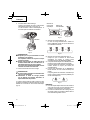
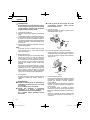
(1) Select a charging method
Depending on the charge method selected, either the
battery is inserted into the charger or the power cord
is plugged into an outlet.
○
Charging a USB device by battery (Fig. 7-a)
○
Charging a USB device from a electrical outlet
(Fig. 7-b)
○
Charging a USB device and battery from a
electrical outlet (Fig. 7-c)
abc
Fig. 7
13
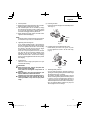
English

2. Installing a socket
(1) Align the square portions of the socket and the anvil
with each other.
(2) Make sure to fi rmly install the socket by pushing it all
the way into the anvil.
(3) When removing the socket, pull it out of the anvil.
Hexagonal
socket Anvil
Fig. 9
CAUTION
●
Please use the designated attachments
which are listed in the operations manual and
metabo HPT’s catalog. Accidents or injuries
could result from not doing so.
●
Make sure to fi rmly install the socket in the anvil.
If the socket is not fi rmly installed it might come
out and cause injuries.
3. Confi rm that the battery is mounted correctly.
4. Check the rotational direction
The bit rotates clockwise (viewed from the rear side)
by pushing the R-side of the push button.
The L-side of the push button is pushed to turn the
bit counterclockwise. (See Fig. 10). (The and
marks are engraved on the body.)
Trigger switch
Push button
Push
Push
marks marks
Fig. 10
CAUTION
The push button can not be switched while the
impact wrench is turning. To switch the push
button, stop the impact wrench, then set the
push button.
(2) Turn the USB power switch ON (Fig. 8)
When you turn the USB power switch ON, the USB
power indicator lamp will light up.
USB power
switch
USB power
indicator lamp
Rubber cover
USB port
USB cable
Fig. 8
(3) Connect the USB cable. (Fig. 8)
Pull back the rubber cover and fi rmly plug in a
commercially available USB cable (appropriate to the
device being charged) into the USB port.
○
When the power cord is not plugged into an outlet and
the battery runs out of power, power output will stop
and the USB power indicator lamp will shut off .
○
When the USB power indicator lamp goes out, change
the battery or plug the power cord into an electrical
outlet.
(4) When charging is completed
○
The USB power indicator lamp will not go out when a
USB device has been completely charged.
To verify charge status, check the USB device.
○
Turn the USB power switch OFF and unplug the power
cord from the electrical outlet. (Fig. 8)
○
Remove the battery from the charger and place the
rubber cover over the USB port.
BEFORE USE
Check the work area to make sure that it is clear of debris
and clutter.
Clear the area of unnecessary personnel. Ensure that
lighting and ventilation is adequate.
OPERATION
1. Selecting the socket matched to the bolt
Be sure to use a socket which is matched to the bolt
to be tightened. Using an improper socket will not only
result in insuffi cient tightening but also in damage to
the socket or nut.
A worn or deformed hex. or square-holed socket will
not give an adequate tightness for fi tting to the nut
or anvil, consequently resulting in loss of tightening
torque.
Pay attention to wear of socket hole, and replace
before further wear has developed.
14
English

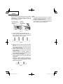
(1) Removing the hook.
Remove the screws fi xing the hook with Philips screw
driver. (Fig. 11)
Screw
Hook
Fig. 11
(2) Replacing the hook and tightening the screws.
Install securely the hook in the groove of power
tool and tighten the screws to fi x the hook fi rmly.
(Fig. 12)
Groove
Screw
Hook
Fig. 12
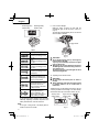
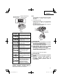
8. Remaining battery indicator
You can check the battery’s remaining capacity by
pressing the remaining battery indicator switch to light
the indicator lamp. (Fig. 13, Table 5)
The indicator will shut off approximately 3 seconds
after the remaining battery indicator switch is pressed.
It is best to use the remaining battery indicator as
a guide since there are slight diff erences such as
ambient temperature and the condition of the battery.
Also, the remaining battery indicator may vary from
those equipped to a tool or charger.
5. Switch operation
○
When the trigger switch is depressed, the tool rotates.
When the trigger is released, the tool stops.
○
The rotational speed can be controlled by varying
the amount that the trigger switch is pulled. Speed
is low when the trigger switch is pulled slightly and
increases as the trigger switch is pulled more.
○
When releasing the trigger switch, the brake will be
applied for immediate stopping.
NOTE
A buzzing noise is produced when the motor is about
to rotate; this is only a noise, not a machine failure.
6. Tightening and loosening bolts
A hex. socket matching the bolt or nut must fi rst be
selected. Then mount the socket on the anvil, and grip
the nut to be tightened with the hex. socket. Holding
the wrench in line with the bolt, press the trigger
switch to impact the nut for several seconds.
If the nut is only loosely fi tted to the bolt, the bolt
may turn with the nut, therefore mistaking proper
tightening. In this case, stop impact on the nut and
hold the bolt head with a wrench before restarting
impact, or manually tighten the bolt and nut to prevent
them slipping.
7. Using the hook
The hook is used to hang up the power tool to your
waist belt while working.
CAUTION
●
When using the hook, hang up the power tool
fi rmly not to drop accidentally.
If the power tool is dropped, it may lead to an
accident.
●
When electing to carry the tool hooked to your
hip belt, make sure to detach the tool bit.
Failure to do so may result in unexpected injury.
●
Install securely the hook. Unless the hook is
securely installed, it may cause an injury while
using.
15
English

Display panel
Remaining battery
indicator lamp Remaining battery
indicator switch
Fig. 13
Table 5
State of lamp Battery Remaining Power
Lights ;
The battery remaining power is
over 75%.
Lights ;
The battery remaining power is
50%–75%.
Lights ;
The battery remaining power is
25%–50%.
Lights ;
The battery remaining power is
less than 25%.
Blinks ;
The battery remaining power
is nearly empty. Recharge the
battery soonest possible
Blinks ;
Output suspended due to high
temperature. Remove the
battery from the tool and allow
it to fully cool down.
Blinks ;
Output suspended due to
failure or malfunction. The
problem may be the battery so
please contact your dealer.
As the remaining battery indicator shows somewhat
diff erently depending on ambient temperature and
battery characteristics, read it as a reference.
NOTE
Do not give a strong shock to the display panel or
break it. It may lead to a trouble.
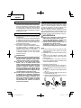
9. How to use the LED light
While the switch is pulled, the LED light will
automatically light up the tip portion of the tool.
(Fig. 14)
The LED light will automatically turn off 10 seconds
after the switch is released.
Trigger switch
Fig. 14
CAUTION
●
Do not expose directly your eye to the light by
looking into the LED light.
If your eye is continuously exposed to the light,
your eye will be hurt.
●
Wipe off any dirt or grime attached to the lens of
the LED light with a soft cloth, being careful not
to scratch the lens.
Scratches on the lens of the LED light can result
in decreased brightness.
10. Tightening mode selector function
CAUTION
●
Do not subject the switch panel to shock or
damage.
●
Select tightening mode while the trigger switch
is released. Failure to do so could result in
malfunction.
Tightening torque can be adjusted according to the type
of work by combined use of the High / Low mode selector
switch and the auto stop mode selector switch. (Fig. 15)
Auto stop mode
selector switch High / Low mode
selector switch
Fig. 15
16
English

(1) High / Low mode selector switch (Fig. 16)
The tightening mode switches between 4 diff erent
rotation speeds each time the High / Low mode
selector switch is pressed.
123 4
Fig. 16
(2) Auto stop mode selector switch (Fig. 17)
Each time the auto stop mode selector switch is
pressed, the auto stop function will switch between
ON and OFF.
○
When auto stop is OFF (auto stop mode indicator
lamp is OFF):
When the trigger switch is pulled, the power tool will
continue to apply impact. (Will not auto stop)
○
When auto stop is ON (auto stop mode indicator lamp
is ON):
When the trigger switch is pulled, the power tool will
apply impact for a preset amount of time and then
auto stop.
Fig. 17
NOTE
○
The appropriate mode diff ers depending on the bolt
and the material being screwed. Tighten in a few test
bolts and adjust the mode setting accordingly.
○
The tightening mode selector function can only be set
after the battery has been installed in the wrench and
the trigger switch has been pulled once.
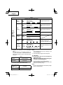
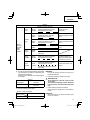
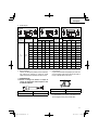
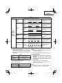
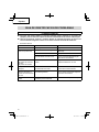
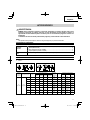
Tightening mode selector function settings
Rotation speed
(/min)
High / Low
mode
Auto stop mode
(Auto Stop Time) Use
1,500 Mode 1
OFF
For work that requires fi ne adjustments such
as when tightening small diameter bolts.
1,800 Mode 2
2,100 Mode 3 For work that requires the power to be
suppressed during tightening.
2,400 Mode 4 For work that requires power and speed
during tightening.
1,500 Mode 1
ON
Approx.
0.5 sec. Tasks including the temporary fastening of
wheel nuts for vehicles or pipe fi ttings
1,800 Mode 2 Approx.
1 sec.
2,100 Mode 3 Approx.
1.5 sec. Temporary fastening of steel frames, etc.
2,400 Mode 4 Approx.
2 sec. Temporary fastening of heavy machinery,
bridges, etc.
17
English

OPERATIONAL CAUTIONS
1. Resting the unit after continuous work
After use for continuous bolt-tightening work, rest the
unit for 15 minutes or so when replacing the battery.
The temperature of the motor, switch, etc., will rise
if the work is started again immediately after battery
replacement, eventually resulting in burnout.
CAUTION
Do not touch the hammer case as it gets very hot
during continuous work.
2. Cautions on use of the speed control switch
This switch has a built-in, electronic circuit which
steplessly varies the rotation speed. Consequently,
when the trigger switch is pulled only slightly (low
speed rotation) and the motor is stopped while
continuously driving in screws, the components of
the electronic circuit parts may overheat and be
damaged.
3. Work at a tightening torque suitable for the bolt under
impact
The optimum tightening torque for nuts or bolts
diff ers with material and size of the nuts or bolts. An
excessively large tightening torque for a small bolt
may stretch or break the bolt. The tightening torque
increases in proportion to the operation time. Use the
correct operating time for the bolt.
4. Holding the tool
Hold the tool fi rmly with both hands. In this case hold
the tool in line with the bolt.
It is not necessary to push the tool very hard. Hold the
tool with a force just suffi cient to counteract the impact
force.
5. Confi rm the tightening torque
The following factors contribute to a reduction of the
tightening torque. So confi rm the actual tightening
torque needed by screwing up some bolts before the
job with a hand torque wrench. Factors aff ecting the
tightening torque are as follows.
(1) Voltage
When the discharge margin is reached, voltage
decreases and tightening torque is lowered.
(2) Operating time
The tightening torque increases when the operating
time increases. But the tightening torque does not
increase above a certain value even if the tool is
driven for a long time.
(3) Diameter of bolt
The tightening torque diff ers with the diameter of the
bolt. Generally a larger diameter bolt requires larger
tightening torque.
(4) Tightening conditions
The tightening torque diff ers according to the torque
ratio; class, and length of bolts even when bolts with
the same size threads are used. The tightening torque
also diff ers according to the condition of the surface of
workpiece through which the bolts are to be tightened.
When the bolt and nut turn together, torque is greatly
reduced.
(5) Using optional parts
The tightening torque is reduced a little when an
extension bar, universal joint or a long socket is used.
(6) Clearance of the socket
A worn or deformed hex. or a square-holed socket will
not give an adequate tightness to the fi tting between
the nut or anvil, consequently resulting in loss of
tightening torque.
Using an improper socket which does not match to the
bolt will result in an insuffi cient tightening torque.
(7) Tightening torque varies, depending on the battery’s
charge level.
18
English

MAINTENANCE AND INSPECTION
WARNING
Pull out battery before doing any inspection or maintenance.
1. Checking the condition of the socket
A worn or deformed hex. or a square-holed socket
will not give an adequate tightness to the fi tting
between the nut or anvil, consequently resulting in
loss of tightening torque. Pay attention to wear of a
socket holes periodically, and replace with a new one
if needed.
2. Check the Screws
Loose screws are dangerous. Regularly inspect them
and make sure they are tight.
CAUTION
Using this power tool with loosened screws is
extremely dangerous.
3. Maintenance of the motor
The motor unit winding is the very “heart” of the power
tool.
Exercise due care to ensure the winding does not
become damaged and/or wet with oil or water.
4. Check for Dust
Dust may be removed with a soft cloth or a cloth
dampened with soapy water.
Do not use bleach, chlorine, gasoline or thinner, for
they may damage the plastics.
5. Inspection of terminals (tool and battery)
Check to make sure that swarf and dust have not
collected on the terminals.
On occasion check prior, during and after operation.
CAUTION
Remove any swarf or dust which may have collected
on the terminals.
Failure to do so may result in malfunction.
6. Disposal of the exhausted battery
WARNING
Do not dispose of the exhausted battery. The
battery must explode if it is incinerated. The
product that you have purchased contains a
rechargeable battery. The battery is recyclable.
At the end of it’s useful life, under various state
and local laws, it may be illegal to dispose of this
battery into the municipal waste stream. Check
with your local solid waste offi cials for details
in your area for recycling options or proper
disposal.
7. Storage
Storing in a place below 104°F (40°C) and out of the
reach of children.
NOTE
Storing lithium-ion batteries
Make sure the lithium-ion batteries have been fully
charged before storing them.
Prolonged storage (3 months or more) of batteries with
a low charge may result in performance deterioration,
signifi cantly reducing battery usage time or rendering
the batteries incapable of holding a charge.
However, signifi cantly reduced battery usage time
may be recovered by repeatedly charging and using
the batteries two to fi ve times.
If the battery usage time is extremely short despite
repeated charging and use, consider the batteries
dead and purchase new batteries.
8. Service and repairs
All quality power tools will eventually require servicing
or replacement of parts because of wear from normal
use. To assure that only authorized replacement parts
will be used, all service and repairs must be performed
by a metabo HPT AUTHORIZED SERVICE CENTER,
ONLY.
CAUTION
In the operation and maintenance of power tools,
the safety regulations and standards prescribed
in each country must be observed.
Important notice on the batteries for the
metabo HPT cordless power tools
Please always use one of our designated genuine
batteries. We cannot guarantee the safety and
performance of our cordless power tool when used
with batteries other than these designated by us, or
when the battery is disassembled and modifi ed (such
as disassembly and replacement of cells or other
internal parts).
19
English

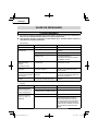
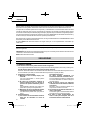
TROUBLESHOOTING GUIDE
WARNING
●
To avoid injury from an accidental start, turn the switch OFF and remove the plug from the power source
or remove the battery from the main body before making any adjustments.
●
All electrical or mechanical repairs should be done only by qualifi ed service technicians. Contact
metabo HPT Authorized Service Center.
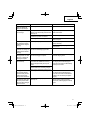
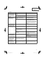
1. Power tool
Problem Possible Cause Possible Solution
Tool doesn’t run No remaining battery power Charge the battery.
Tool suddenly stopped Tool was overburdened Get rid of the problem causing the
overburden.
The battery is overheated. Let the battery cool down.
The trigger switch was held down for
5 minutes or more. This is not a malfunction.
The motor was automatically stopped to
prevent failure of the tool.
Tool sockets
-can’t be attached
-fall off
-can’t be removed
The shape of the attachment portion
doesn’t match Be sure to use 12.7 mm square drive
sockets.
Switch can’t be pulled Forward/reverse selector button is
positioned halfway Press the button fi rmly into position for the
desired direction of rotation.
An abnormal high-pitched
noise occurs when the
trigger switch is pulled.
The trigger switch is being pulled only
slightly. This is not a malfunction.
It does not occur if the trigger switch is
pulled more fully.
Battery cannot be
installed Attempting to install a battery other than
that specifi ed for the tool. Please install a multi volt type battery.
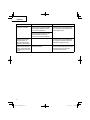
2. Charger
Symptom Possible cause Remedy
The charge indicator lamp
is rapidly fl ickers purple,
and battery charging
doesn’t begin.
The battery is not inserted all the way. Insert the battery fi rmly.
There is foreign matter in the battery
terminal or where the battery is attached. Remove the foreign matter.
The charge indicator lamp
blinks red, and battery
charging doesn’t begin.
The battery is not inserted all the way. Insert the battery fi rmly.
The battery is overheated. If left alone, the battery will automatically
begin charging if its temperature
decreases, but this may reduce battery
life. It is recommended that the battery be
cooled in a well-ventilated location away
from direct sunlight before charging it.
20
English
La page charge ...
La page charge ...
La page charge ...
La page charge ...
La page charge ...
La page charge ...
La page charge ...
La page charge ...
La page charge ...
La page charge ...
La page charge ...
La page charge ...
La page charge ...
La page charge ...
La page charge ...
La page charge ...
La page charge ...
La page charge ...
La page charge ...
La page charge ...
La page charge ...
La page charge ...
La page charge ...
La page charge ...
La page charge ...
La page charge ...
La page charge ...
La page charge ...
La page charge ...
La page charge ...
La page charge ...
La page charge ...
La page charge ...
La page charge ...
La page charge ...
La page charge ...
La page charge ...
La page charge ...
La page charge ...
La page charge ...
La page charge ...
La page charge ...
La page charge ...
La page charge ...
La page charge ...
La page charge ...
La page charge ...
La page charge ...
La page charge ...
La page charge ...
La page charge ...
La page charge ...
La page charge ...
La page charge ...
La page charge ...
La page charge ...
-
 1
1
-
 2
2
-
 3
3
-
 4
4
-
 5
5
-
 6
6
-
 7
7
-
 8
8
-
 9
9
-
 10
10
-
 11
11
-
 12
12
-
 13
13
-
 14
14
-
 15
15
-
 16
16
-
 17
17
-
 18
18
-
 19
19
-
 20
20
-
 21
21
-
 22
22
-
 23
23
-
 24
24
-
 25
25
-
 26
26
-
 27
27
-
 28
28
-
 29
29
-
 30
30
-
 31
31
-
 32
32
-
 33
33
-
 34
34
-
 35
35
-
 36
36
-
 37
37
-
 38
38
-
 39
39
-
 40
40
-
 41
41
-
 42
42
-
 43
43
-
 44
44
-
 45
45
-
 46
46
-
 47
47
-
 48
48
-
 49
49
-
 50
50
-
 51
51
-
 52
52
-
 53
53
-
 54
54
-
 55
55
-
 56
56
-
 57
57
-
 58
58
-
 59
59
-
 60
60
-
 61
61
-
 62
62
-
 63
63
-
 64
64
-
 65
65
-
 66
66
-
 67
67
-
 68
68
-
 69
69
-
 70
70
-
 71
71
-
 72
72
-
 73
73
-
 74
74
-
 75
75
-
 76
76


Hikoki WR36DE Manuel utilisateur
- Catégorie
- Clés à chocs électriques
- Taper
- Manuel utilisateur
dans d''autres langues
- English: Hikoki WR36DE User manual
- español: Hikoki WR36DE Manual de usuario
Documents connexes
-
Hikoki CR18DB Manuel utilisateur
-
-
-
-
-
-
-
-
Hikoki M3612DA Manuel utilisateur
-