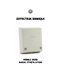
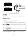
SEISMIC DETECTOR
MODEL: RK66S
INSTALLATION INSTRUCTIONS
EN
EN
FR
IT
CN
ES

2
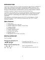
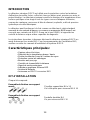
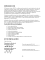
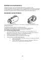
INTRODUCTION
The RISCO Seismic Detector is used for the protection against break-in attempts of
vaults, safes, reinforced concrete walls, steel armored cabinets and doors. The
seismic detector monitors the vibration and temperature of a specific surface and
will react to all known types of intruder attacks, such as sledge hammers, diamond
head drills, explosives, hydraulic pressure tools and thermal tools.
The detector can operate both as a regular relay detector connected to any control
panel, or as a BUS accessory when connected to RISCO Group's control panels
via the RS485 BUS, empowering it with unique remote control and diagnostic
capabilities.
The instructions set forth below describe the RISCO seismic detector in Stand
Alone & BUS mode. For BUS installation programming, see RISCO System
installation manuals
Main Features:
• Piezo sensor
• Low/High temperature detection
• Detection range up to 5 meters (16 feet) radius
• Tamper protection
• Anti drilling shield
• Remote sensitivity control
• Analogue signal output
• Bar graph LED indicator
• Remote self test
• Stand-alone or RISCO BUS connection
INSTALLATION KIT
Each kit includes:
Wall structure fastening sets:
Expanding plugs M6 x 16
Flat head machining screw M6 X 16
Metallic structure fastening sets:
Inner Tooth Washer M4
Pan Head Machining Screw M4 X 10

3
External Test Generator
Detector
Mounting Plate
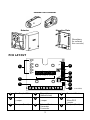
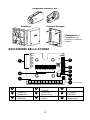
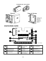
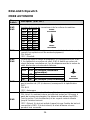
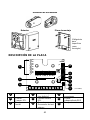
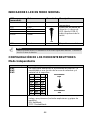
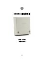
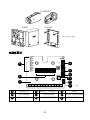
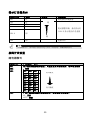
PCB LAYOUT
Bar Graph LEDs
Dipswitches
(default state)
Terminal Blocks
Tamper EOL
Jumper
Alarm EOL
Jumper
Stand
Alone/BUS
Jumper
Tamper (Front )
External Test
Generator
Connector
Tamper (Back)
ON
1 2 3 4
ON
1 2 3 4
ON
1 2 3 4
+ 12V -YEL GRN NO C NC TAMPER SENS A.OUT TEST
Tamper EOL
Alarm EOL
S.A/Bus
Ext. Test
LD1
LD2
LD3
LD4
LD5
LD6
LD7
LD8
LD9
J15
J13
J12
J2
1
2
3
4
5
6
8
7
SW1
SW2
SW3
SW4
SW5
SW6
SW7
SW8
SW9
SW10
SW11
SW12
9
1
2
3
4
5
6
7
8
9
(Mandatory
for surfaces
like concrete)
(not visible)

4
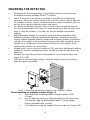
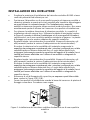
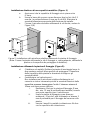
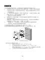
MOUNTING THE DETECTOR
• Determine the mounting position. Potential false alarm sources must be
accounted for when installing RK66S, Therefore:
• Attach the sensor to a surface as isolated as possible from extraneous
vibrations, with close contact between the concrete surface and the detector.
For metallic surfaces, remove residual paint from sensor installation site. Do
not use silicon grease between sensor and object!
• For maximum vibration detection, the concrete surface should be smooth.
Use the mounting plate (see Figure 2) when mounting on drill-resistant steel,
brick or concrete surfaces. The plate can also be welded onto metallic
surfaces.
• Adjust dipswitch settings for sensitivity; time and other parameters (see
Dipswitch settings, below) for background vibration – bearing in mind the
inverse relation between detection range and sensitivity and the construction
material of the object to be monitored. Detectors with high sensitivity can be
spaced up to 5m apart on secure protected surfaces (for example, steel),
confirmed by hammer or scratch tests.
• Hinged doors, such as those on safes or ATM, and other attachments without
continuous acoustic transmission paths, should be protected with their own
detectors.
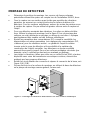
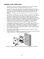
• Remove the cover fixing screws to separate the cover from the base, see
Figure 1(A) / 2(B).
• Drill holes on the mounting surface, using the detector base or mounting
plate as a guide, as follows:
Figure 1: Mounting the detector directly onto a metallic surface
Direct mounting on a metallic surface (Figure. 1)
a. Ensure that the mounting surface is level to within 1/128”
(0.1mm).
b. Use the detector base as a drilling template for the three holes
(3.2 mm dia.) and tap M4 thread at least ¼” (6 mm) deep.
Deburr threaded holes in metal.
c. Fit the detector using the supplied fixing screws, see Figure 1(B).
A
B

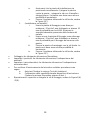
5
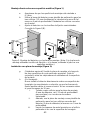
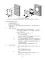
Figure 2: Mounting the detector using the mounting plate. (Note: Affix the mounting
plate using fixing screws or optionally, by welding the plate to a metallic surface.)
Installation using mounting plate (Figure 2):
a. (Optional metal welding) Weld the mounting plate along the two
provided vertical oblong cutout surfaces. Tap off slag and
remove weld splatter from the plate surface.
b. (On concrete) :
Never install the detector directly on a bare or plastered concrete
surface, since bending forces may cause damage to the seismic
sensor. Plaster of less than 10mm need not be removed.
i. Drill four holes for mounting plate (8 mm dia, min 35
mm depth for anchor; using a sintered carbide bit.
ii. Also, use the mounting plate as a drilling template
for the three threaded detector holes (5 mm dia) at
least 3 mm deep.
iii. Insert supplied metal plugs into drilled hole flush
with the concrete surface
iv. Ensure that the mounting plate is correctly
positioned. Press the mounting plate onto surface,
knock in screw with plug and tighten well. The plate
should not be capable of rotation.
v. Fit the detector using the supplied fixing screws, see
Figure 2(C).
c. (On metal) :
i. Use the mounting plate as a drilling template for the
four holes (5 mm dia.) and tap M6 thread at least 10
mm deep. Deburr threaded holes in metal.
ii. Also, use the mounting plate as a drilling template
for the three threaded detector holes (5 mm dia) at
least 3 mm deep.
iii. Affix the mounting plate with the supplied screws.
The plate should not be capable of rotation
iv. Fit the detector using the supplied fixing screws, see
Figure 2(C).
A
B
C

6
• Connect wiring; Refer to Terminal Blocks section.
• Set Jumpers; Refer to Jumper Selection section.
• Set Dipswitches; Refer to Dipswitch Settings section.
• To verify detector operation, perform:
a. A self test (See Testing the Detector section).
b. Sensitivity calibration using an external test generator (See
External Test Generator section).
• Replace the cover and tighten the cover fixing screws; See Figure 1(A) / 2(B).
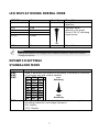
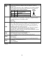
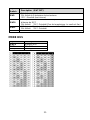
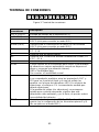
TERMINAL BLOCK LAYOUT
Figure 3: Terminal Block Layout
Terminal
Block
Description
+12V (RED)
Power supply positive (+) input voltage
- (BLK)
Power supply negative (-) input voltage
YEL
Used for data communication with RISCO panels (only for
BUS connection)
GRN
Used for data communication with RISCO panels (only for
BUS connection)
NO
Alarm Normally Opened relay output, 24VDC.0.1A
C
Alarm Common relay output
NC
Alarm Normally Closed relay output, 24VDC.0.1A
TAMPER
N.C. Tamper Switch, 24VDC.0.1A
SENS
Remote sensitivity control for lowering vibration sensitivity for
ATM-type dispensers when cash is being disbursed and
internal vibration generated.
GND = Low sensitivity
Not Connected = Reguler sensitivity
A.OUT
Analog signal output: Connect a multimeter/scope or an
analogic tester between the A.OUT and -12V terminals, to
view the noise and signal voltage levels (in parallel to the LED
bar representation). In the absence of vibrations, the voltage
signal is 0V, and it increases as it detects vibrations.
If the voltage measured (in absence of vibrations) doesn't
remain stable but continues to increase, it means that
environmental noise is being captured and therefore the
detector sensitivity must be reduced.
TEST
A short between TEST and GND activates the Remote Test
(see Dipswitch Settings 8 and 9).
(Not relevant for BUS mode.)
SENS A.OUT TEST
+ 12V - YEL GRN NO C NC TAMPER

7
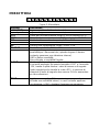
LED DISPLAY DURING NORMAL MODE
LED ON
Color
Severity
Description
LD1
Red
Temperature alarm
detection
LD2
Red
Vibration alarm
detection: Bar graph
(from LED8–2) indicating
signal power.
LD3
Yellow
LD4-8
Green
LD9
Green
Power On
NOTE:
During Test mode the LED displays have a different meaning. Refer to the section:
Testing the detector.
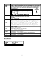
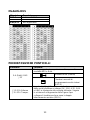
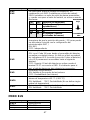
DIPSWITCH SETTINGS
STANDALONE MODE
Dipswitch
Description (SW7 OFF)
SW1
SW2
SW3
Used to determine the detector's sensitivity. Sensitivity is a function
of coverage area and surface material.
SW1
SW2
SW3
*OFF
*OFF
*OFF
ON
OFF
OFF
OFF
ON
OFF
ON
ON
OFF
OFF
OFF
ON
ON
OFF
ON
OFF
ON
ON
ON
ON
ON
SW4
Used to detect single and extremely brief and intense signals
(including explosions and sledge hammers).
ON: Enable
*OFF: Disable
LOW
HIGH
High
Sensitivity
Low
Sensitivity

8
Dipswitch
Description (SW7 OFF)
SW5
SW6
Used to adjust the integration time. In combination with SW1-3 they
establish a threshold value; SW5-6 establishes a cumulative alarm
signal value which, when exceeding the threshold value, triggers
an alarm event.
SW5
SW6
Duration (in sec.)
*OFF
*OFF
10 (example: vending machine)
ON
OFF
26
OFF
ON
46
ON
ON
80 (example: bank vault)
SW7
Used to determine Stand Alone or BUS mode (Ensure that the J12
position (as below) matches the SW7 spec. )
ON: BUS
*OFF: Stand Alone
SW8
Used to determine Local or Remote Test
ON: Local. An internal self test is performed every 24 hours from
power-up. Test failure lights up the LEDs (see the Testing the
Detector section) and the LEDs remain lit until the next self test.
*OFF: Remote. A test is activated whenever the TEST input is
connected to GND. If the test passes, the alarm relay opens for
three seconds.
SW9
External test generator
ON: Enable External Test Generator
*OFF: Disable (internal test)
SW10
Used to enable the temperature sensor (alarm temperature
threshold of +85°C (+185°F))
ON: Enable *OFF: Disable (No temp. threshold is set)
SW11
Used to determine LEDs operation
ON: Enable *OFF: Disable
SW12
Not used
BUS MODE
Dipswitch
Description
SW1-5
BUS Address
SW7
ON: BUS
SW6,8-12
Not Applicable
Low
Sensitivity
High
Sensitivity

9
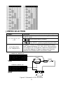
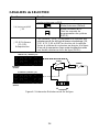
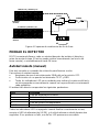
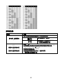
JUMPER SELECTION
Jumper
Function
S.A (Stand Alone) /BUS
J12
Used to enable tamper indication during Stand Alone
or BUS mode.
Stand Alone mode (Default).
BUS connection mode.
(See RISCO system programming manuals).
J13: Alarm EOL
J15: Tamper EOL
Jumpers J13 and J15 allow for the selection of Alarm
and Tamper resistance (1K, 2.2K, 4.7K, 5.6K and 6.8K)
according to the control panel. Follow the terminal block
connection diagram in Figure 4 when connecting the
detector to a Double End Of Line (DEOL) zone.
Figure 4: Schematic of EOL Resistors
Panel DEOL
TAMPER
ALARM
C NC TAMPER
NO
RESISTOR
(Default)
1K 2.2K 4.7K 5.6K 6.8K
TAMPER EOL JUMPERS (J15)
NO
RESISTOR
(Default)
1K 2.2K 4.7K 5.6K 6.8K
ALARM EOL JUMPERS (J13)

10
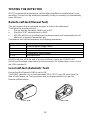
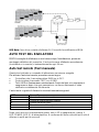
TESTING THE DETECTOR
RISCO recommends performing a self test after installation and before final cover
mounting. The test can be performed manually (locally or remotely) or automatically
every 24 hours
Remote self-test (Manual Test)
This test requires that a command be given in order to be performed.
To activate the remote self-test:
• Ensure that the Dipswitch SW8 is set to OFF.
• Short the TEST terminal block to GND.
• All LEDs will turn on to indicate test commencement and sequentially turn off
after each successful parameter test.
The detector unit self test examines the following parameters:
LED
Trouble
1
External power supply failure
2
Internal voltage faulty
4
Piezo sensor failure
5
Temperature sensor failure
3, 6-9
Not Applicable
All LEDs will turn off at the end of a successful test, except the POWER LED
(LED9) and the alarm relay opens for three seconds. If a malfunction occurs, one of
the LEDs remains lit.
Local self-test (Automatic Test)
Ensure that the Dipswitch SW8 is set to ON.
The RK66S detector runs a local/automatic SELF-TEST every 24 hours from the
time of initial power on. Test procedure and result presentation is as per the
Remote self-test above.
Front view
Rear view

11
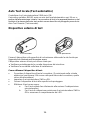
Attach to the concrete surface, using the supplied mounting screw in this hole
opening.
The external test generator can be used to:
Periodically verify proper functioning of the detector
Observe the detector’s sensitivity during installation
To use the test generator:
• Connect the test generator to J2 on the PC board (with the polarity resulting
from the red wire connected to the plug pin closest to the terminal block, in
other words, the lowest)
• Switch SW9 to ON.
• Attach the test generator to the concrete surface.
• Perform test, as follows:
a. For remote test, see the DIPSWITCH Settings section
b. For calibration test, Switch SW8 to ON and observe the LEDs
Specifications
In order to continue improving the product, RISCO Group reserves the right to
change specifications and/or designs without prior notice.
Ordering Information
Model
Description
RK66S
Seismic Detector
Coverage
Up to 5 meters (16 feet) radius
Operating voltage
9 to 16 VDC
Current consumption
Typically 20mA @ 12VDC
RFI immunity
According to EN50130-4
Alarm contacts
24VDC, 0.1A, N/C and N/O
Tamper contacts
24VDC, 0.1A
Alarm contact hold time
2.5 seconds
Operating temperature
-40°C to +70°C (-40°F to 158°F)
Storage temperature
-50°C to +70°C (-58°F to 158°F)
Ingress protection (IP) rating
IP43
Impact Rating
IK08
RFI immunity
According to EN50130-4
Dimensions (L x H x W)
102 X 27.5 X 80.2 mm
(4.0” X 1.1” X 3.2”)
Weight
220 g ( 7.7 oz)

12
NOTES

MICROFONO SELETTIVO
MODELLO: RK66S
ISTRUZIONI DI INSTALLAZIONE
IT

14
INTRODUZIONE
Il microfono selettivo di RISCO è utilizzato per la protezione di caveau, casseforti,
mura di cemento armato, armadi e porte blindate. Il microfono selettivo rileva la
vibrazione e la temperatura di una specifica superficie e reagisce a tutte le
tipologie di attacco conosciute come ad esempio punte di diamante, esplosivi, colpi
di mazza, lancia termica e dispositivi idraulici di pressione.
Il rivelatore può funzionare sia tramite connessione a relè ad una qualsiasi centrale
antifurto o tramite connessione BUS RS485 con le centrali antifurto RISCO. In
quest’ultimo caso il microfono selettivo può essere configurato e testato tramite
tastiera del sistema o tramite PC.
Le istruzioni che seguono descrivono il microfono selettivo RISCO sia nella
modalità a Relè che in quella BUS. Per il collegamento via BUS far riferimento
anche al manuale di installazione della centrale RISCO utilizzata.
Caratteristiche principali
• Sensore piezoelettrico
• Rilevazione temperatura Bassa/Alta
• Portata fino a 2.5 metri di raggio
• Protezione tamper
• Schermo anti-perforazione
• Controllo remoto della sensibilità
• Uscita segnale analogico
• Indicatore grafico a LED
• Auto-test remoto
• Collegamento a relè o via BUS RISCO
KIT DI INSTALLAZIONE
Ogni kit include:
Set di fissaggio comprendente:
Tasselli per viti M6 x 16
Viti a testa piatta tipo M6 X 16
Set metallico di fissaggio comprendente:
Rondella dentata per viti M4
Viti per metallo a testa cilindrica
tipo M4 X 10

15
Dispositivo esterno di test
Rivelatore
Piastra di fissaggio
DESCRIZIONE DELLA SCHEDA
Indicatori LED
Microinterruttori
(default)
Morsettiera
Ponticello
Tamper EOL
Ponticello
Allarme EOL
Ponticello
Relè/BUS
Tamper
(Apertura)
Connettore Test
esterno
Tamper
(Rimozione)
ON
1 2 3 4
ON
1 2 3 4
ON
1 2 3 4
+ 12V -YEL GRN NO C NC TAMPER SENS A.OUT TEST
Tamper EOL
Alarm EOL
S.A/Bus
Ext. Test
LD1
LD2
LD3
LD4
LD5
LD6
LD7
LD8
LD9
J15
J13
J12
J2
1
2
3
4
5
6
8
7
SW1
SW2
SW3
SW4
SW5
SW6
SW7
SW8
SW9
SW10
SW11
SW12
9
1
2
3
4
5
6
7
8
9
(Obbligatoria per
l’installazione su
superfici in cemento
armato)
(non visibile)

16
INSTALLAZIONE DEL RIVELATORE
• Scegliere la posizione di installazione del microfono selettivo RK66S e tener
conto dei potenziali falsi allarmi per cui:
• Posizionare il dispositivo su di una superficie quanto più immune possibile a
vibrazioni estranee e quanto più vicino possibile alla superficie da proteggere
se quest’ultima è in cemento armato. Per l’installazione su superfici
metalliche rimuovere da queste ultime eventuali residui di vernice. Non usare
assolutamente pasta di silicone tra il sensore e la superficie di installazione.
• Per ottenere la migliore rilevazione di vibrazione possibile, le superfici di
installazione devono essere lisce. Utilizzare la piastra di montaggio (vedere
la Figura 2) quando si effettua l’installazione su di una superficie di mattoni,
calcestruzzo o su di una superficie metallica resistente al trapano. La piastra
di fissaggio può anche essere saldata sulle superfici metalliche.
• Regolare tramite i microinterruttori la sensibilità, il tempo di intervento e gli
altri parametri (vedere la sezione Predisposizione dei microinterruttori).
Ricordare la relazione tra la sensibilità ed il materiale componente la
superficie da proteggere considerando che i microfoni configurati per un’alta
sensibilità possono essere distanziati fino a 5 metri dalla superficie da
proteggere (ad esempio quando la superficie dell’oggetto è di metallo) la cui
verifica può essere effettuata con l’utilizzo di un martello o sfregando la
superficie stessa.
• Rimuovere le viti di fissaggio del coperchio per separare quest’ultimo dalla
base, vedere la Figura 1(A) / 2(B).
• Forare la superficie di installazione usando la base del sensore o la piastra di
fissaggio come dima. Procedere come segue:
Figura 1: Installazione del microfono selettivo direttamente su di una superficie
metallica
A
B

17
Installazione diretta su di una superficie metallica (Figura. 1)
a. Assicurarsi che la superficie di fissaggio sia in piano entro
0.1mm.
b. Usare la base del sensore come dima per fare tre fori (da 3.2
mm dia.) e profondi almeno 6 mm per le viti M4. Eliminare le
eventuali sbavature provocate dalla foratura del metallo.
c. Fissare il microfono selettivo utilizzando le viti fornite, vedere la
Figura 1(B).
Figura 2: Installazione del microfono selettivo utilizzando la piastra di fissaggio.
(Nota: Fissare la piastra utilizzando le viti di fissaggio o, opzionalmente, saldando la
piastra se la superficie da proteggere è metallica).
Installazione utilizzando la piastra di fissaggio (Figura 2):
d. (Saldatura sul metallo) Saldare la piastra di montaggio lungo le
due aperture verticali alla superficie da proteggere. Rimuovere
dalla superficie della piastra le sbavature di stagno e gli
eventuali detriti.
e. (Installazione sul calcestruzzo) :
Non installare mai il microfono selettivo direttamente sul
cemento a vista o intonacato poiché le eventuali flessioni della
superficie possono danneggiare l’unità. L’intonaco minore di
10mm non deve essere rimosso.
i. Realizzare 4 fori per la piastra di fissaggio (8 mm
dia., min. 35 mm di profondità per tassello) usando
una punta specifica per il calcestruzzo.
ii. Usare la piastra di fissaggio come dima per
realizzare i 3 fori da 5 mm di diametro e almeno 3
mm di profondità per il fissaggio del sensore sulla
piastra.
iii. Inserire i tasselli in metallo in dotazione a filo foro
con la superficie del calcestruzzo.
A
B
C

18
iv. Assicurarsi che la piastra di installazione sia
posizionata correttamente. Spingere la piastra
contro la parete, , spingere le vite con il tassello e
stringerle bene. La piastra non deve avere alcuna
possibilità di movimento.
v. Fissare il rivelatore utilizzando le viti fornite, vedere
la Figura 2(C).
f. (Installazione sul metallo) :
i. Usare la piastra di fissaggio come dima per
realizzare i 3 fori da 5 mm di diametro e almeno 10
mm di profondità per le viti M6. Eliminare le
eventuali sbavature provocate dalla foratura del
metallo.
ii. Usare ancora la piastra di fissaggio come dima per
realizzare i 3 fori da 5 mm di diametro e almeno 3
mm di profondità per il fissaggio del sensore sulla
piastra.
iii. Fissare la piastra di montaggio con le viti fornite. La
piastra non deve avere alcuna possibilità di
movimento.
iv. Fissare il rivelatore utilizzando le viti fornite, vedere
la Figura 2(C).
• Cablaggio; far riferimento alla sezione Morsettiera.
• Impostare i ponticelli; far riferimento alla sezione Predisposizione dei
ponticelli.
• Impostare i microinterruttori; far riferimento alla sezione Predisposizione
microinterruttori.
• Per verificare il funzionamento del microfono selettivo procedere come
segue:
a. Auto-test (Vedere la sezione Test del rivelatore).
b. Calibrazione della sensibilità tramite dispositivo di test esterno
(Vedere la sezione Dispositivo esterno di test ).
• Riposizionare il coperchio e stringere le viti di fissaggio, vedere la Figura 1(A)
/ 2(B).

19
MORSETTIERA
Figura 3: Morsettiera
Morsetti
Descrizione
+12V (RED)
Ingresso positivo di alimentazione (+)
- (BLK)
Ingresso negativo di alimentazione (-)
YEL
Usato per la comunicazione via BUS con le centrali RISCO
GRN
Usato per la comunicazione via BUS con le centrali RISCO
NO
Uscita a relè normalmente aperta, 24Vcc. 0.1A
C
Riferimento comune del relè
NC
Uscita a relè normalmente chiusa, 24VDC.0.1A
TAMPER
Uscita Tamper N.C. , 24Vcc. 0.1A
SENS
Controllo remoto della sensibilità (usato per diminuire la
sensibilità per i Bancomat che, quando erogano il denaro
contante, generano una vibrazione interna).
GND = Bassa sensibilità
Non collegato = sensibilità Reguler
A.OUT
Uscita segnale analogico: usato per connettere un multimetro
o un tester analogico tra questo morsetto A.OUT e il morsetto
-12V, tramite il quale rilevare i valori di rumore e di segnale
(valori riportati anche tramite la scala LED) . In assenza di
vibrazioni il livello di segnale deve essere 0 Volt e aumentare
se rileva vibrazioni.
TEST
Applicare un negativo (0V) a questo ingresso quando si
richiede una sensibilità minore, in caso contrario applicare
una tensione (+12V) o lasciare l’ingresso non connesso.
SENS A.OUT TEST
+ 12V - YEL GRN NO C NC TAMPER

20
DISPLAY LED NEL NORMALE FUNZIONAMENTO
LED ON
Colore
Gravità
Descrizione
LD1
Rosso
Rilevazione allarme
temperatura
LD2
Rosso
Rilevazione allarme
vibrazione: La scala LED
(LED da 8 a 2) indicano
il livello di segnale.
LD3
Giallo
LD4-8
Verde
LD9
Verde
Alimentazione
NOTA:
Nella modalità Test il display a LED ha una funzione differente. Fare riferimento alla
sezione: Test del microfono selettivo.
PREDISPOSIZIONE MICROINTERRUTTORI
Modalità a Relè
Microint.
Descrizione (SW7 OFF)
SW1
SW2
SW3
Usato per impostare la sensibilità del rivelatore.
La sensibilità dipende dall’area e al materiale della superficie ove è
fissato il rivelatore.
SW1
SW2
SW3
*OFF
*OFF
*OFF
ON
OFF
OFF
OFF
ON
OFF
ON
ON
OFF
OFF
OFF
ON
ON
OFF
ON
OFF
ON
ON
ON
ON
ON
SW4
Usato per rilevare segnali estremamente corti ed intensi (incluso
esplosioni e colpi di mazza).
ON: Abilitato
*OFF: Disabilitato
Alta
sensibilità
Bassa
sensibilità
La page est en cours de chargement...
La page est en cours de chargement...
La page est en cours de chargement...
La page est en cours de chargement...
La page est en cours de chargement...
La page est en cours de chargement...
La page est en cours de chargement...
La page est en cours de chargement...
La page est en cours de chargement...
La page est en cours de chargement...
La page est en cours de chargement...
La page est en cours de chargement...
La page est en cours de chargement...
La page est en cours de chargement...
La page est en cours de chargement...
La page est en cours de chargement...
La page est en cours de chargement...
La page est en cours de chargement...
La page est en cours de chargement...
La page est en cours de chargement...
La page est en cours de chargement...
La page est en cours de chargement...
La page est en cours de chargement...
La page est en cours de chargement...
La page est en cours de chargement...
La page est en cours de chargement...
La page est en cours de chargement...
La page est en cours de chargement...
La page est en cours de chargement...
La page est en cours de chargement...
La page est en cours de chargement...
La page est en cours de chargement...
La page est en cours de chargement...
La page est en cours de chargement...
La page est en cours de chargement...
La page est en cours de chargement...
La page est en cours de chargement...
La page est en cours de chargement...
La page est en cours de chargement...
La page est en cours de chargement...
La page est en cours de chargement...
La page est en cours de chargement...
La page est en cours de chargement...
La page est en cours de chargement...
La page est en cours de chargement...
La page est en cours de chargement...
La page est en cours de chargement...
La page est en cours de chargement...
-
 1
1
-
 2
2
-
 3
3
-
 4
4
-
 5
5
-
 6
6
-
 7
7
-
 8
8
-
 9
9
-
 10
10
-
 11
11
-
 12
12
-
 13
13
-
 14
14
-
 15
15
-
 16
16
-
 17
17
-
 18
18
-
 19
19
-
 20
20
-
 21
21
-
 22
22
-
 23
23
-
 24
24
-
 25
25
-
 26
26
-
 27
27
-
 28
28
-
 29
29
-
 30
30
-
 31
31
-
 32
32
-
 33
33
-
 34
34
-
 35
35
-
 36
36
-
 37
37
-
 38
38
-
 39
39
-
 40
40
-
 41
41
-
 42
42
-
 43
43
-
 44
44
-
 45
45
-
 46
46
-
 47
47
-
 48
48
-
 49
49
-
 50
50
-
 51
51
-
 52
52
-
 53
53
-
 54
54
-
 55
55
-
 56
56
-
 57
57
-
 58
58
-
 59
59
-
 60
60
-
 61
61
-
 62
62
-
 63
63
-
 64
64
-
 65
65
-
 66
66
-
 67
67
-
 68
68


dans d''autres langues
- italiano: Risco RK66S Manuale utente
- English: Risco RK66S User manual
- español: Risco RK66S Manual de usuario
Documents connexes
-
Risco RK66S Manuel utilisateur
-
Risco WatchOUT XTreme 315DT Installation Instructions Manual
-
Ris Ind. LuNAR 200DTG3 Manuel utilisateur
-
-
-
Risco Industrial LuNAR RK200DTG3 Guide d'installation
-
-
-