La page est en cours de chargement...

DS80PS55-001D LBT80779
Libretto istruzioni
Instruction manual
Livret d'instructions
Bedienungsanleitung
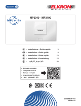
AS500/RPT
Unità di Alimentazione
Supplementare con ripetitore
Additional Power Supply with
repeater
Alimentation supplémentaire avec
répétiteur
Zusätzliches Netzteil mit Verstärker
F
GB
I
D

2 AS500/RPT
ITALIANO
ATTENZIONE: In questo documento sono riportate solo alcune indicazioni essenziali sul
prodotto. Per ulteriori e dettagliate informazioni fare riferimento ai manuali delle centrali MP500.
Alimentatore in CAT II 2500 V. L’alimentatore che, una volta installato, è soggetto a tensioni
transitorie superiori a quelle della categoria di sovratensione di progetto, necessita di una
protezione supplementare delle tensioni transitorie esterne all’apparecchiatura.
DESCRIZIONE GENERALE
L’unità di alimentazione supplementare AS500 è un dispositivo opzionale delle centrali MP500/8 e
MP500/16. È dotata di una scheda elettronica che integra al suo interno un’espansione tipo
EP508 collegata direttamente al BUS di centrale, un modulo repeater per estendere la tratta del
BUS di centrale e un’unità supplementare di alimentazione in grado di alimentare i dispositivi
connessi al sistema.
L’unità AS500 è dotata di:
8 ingressi;
1 ingresso SAB bilanciato;
3 uscite (1 uscita a relè e 2 elettriche).
1 alimentatore switching;
alloggiamento interno per batteria;
alloggiamento interno per 2 espansioni.
INSTALLAZIONE
Posizionare il tamper in posizione A o S, in funzione del tipo di applicazione desiderata:
in posizione A, per la sola protezione contro l’apertura
in posizione S, per la protezione contro l’apertura e l’asportazione, utilizzando in questo caso
la vite con tassello per il sostegno del contatto.
In entrambi i casi occorre collegare il connettore del tamper alla scheda.
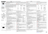
T Fori di fissaggio a parete
Il fissaggio a parete avviene tramite 3 tasselli
autobloccanti della dimensione massima di 8mm.
D Fori di fissaggio per 2 espansioni EP508 opzionali
F Anello di fissaggio fascetta per cavo di alimentazione
F
D
F
T

AS500/RPT 3
COLLEGAMENTO RETE E BATTERIA
Il collegamento deve essere effettuato tramite cavo con guaina a 3 conduttori (fase-neutro-terra).
Dal cavo deve essere opportunamente rimossa la guaina, i conduttori di L, N, e Terra dopo essere
stati opportunamente spellati, dovranno essere collegati ai corrispondenti morsetti della
morsettiera dell’ AC/DC converter.
Il cavo dovrà poi essere fissato, tramite una fascetta, all’apposito anello di fissaggio.
Per il cavo di alimentazione di rete deve essere previsto un mezzo di sezionamento esterno alla
centrale con opportuna distanza di separazione tra i contatti (min. 3 mm).
Il mezzo di sezionamento deve disconnettere contemporaneamente Fase e Neutro.
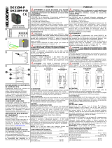
1. Per effettuare il collegamento di terra dell’apparecchiatura, crimpare il terminale faston “A”
(fornito a corredo) sul cavo di terra che andrà inserito in uno dei terminali faston sulla parete del
cassonetto (C).
2. Collegare il cavetto di terra al faston del coperchio (B).
3. Bloccare i cavi fissandoli con la fascetta fornita a corredo al punto di ancoraggio (F).
I cavi impiegati devono rispondere alla norma IEC 60332-1-2 se di sezione 0,5 mm² o
superiore, oppure alla norma IEC 60332-2-2 se di sezione inferiore a 0,5 mm².
A
F
C
B

4 AS500/RPT
Nell’alimentatore è previsto l’uso di una batteria di tipo ricaricabile al piombo da 12 V, 18 Ah.
La batteria da utilizzare deve:
Essere di tipo VRLA (Valve Regulated Lead Acid)
Avere un involucro con classe di infiammabilità UL94V-1 o migliore
Essere conforme alle normative IEC 60896-21:2004, IEC 60896-22:2004
La sostituzione della batteria deve essere eseguita esclusivamente da personale qualificato.
CIRCUITO AS500/RPT
Morsettiera
Gruppo
Morsetto
Collegamento/ Funzione
LED dati
IN
TX
LED verde (TX BUS centrale)
(trasmissione dati verso la centrale)
RX
LED giallo (RX BUS centrale)
(ricezione dati dalla centrale)
OUT
TX
LED verde (TX BUS esteso)
(trasmissione dati verso il BUS esteso)
RX
LED giallo (RX BUS esteso)
(ricezione dati dal BUS esteso)
LED
Verde
PWR
Presenza rete/batteria
Giallo
BL
Stato batteria
Giallo
FUSE
Anomalia alimentazioni +SR; +; +BUS OUT; +D

AS500/RPT 5
COLLEGAMENTI
IMPIANTO CON PIU’ ALIMENTATORI SUPPLEMENTARI
Somma delle tratte di ciascun BUS (BUS primario = BUS secondario) = 400 m
Distanza BUS punto/punto = (BUS primario + BUS secondario) = 1200 m
Somma delle tratte di tutti i BUS = 6400 m
ATTENZIONE! Non è consentito collegare in serie tra loro due unità di alimentazione.
MP500/8

6 AS500/RPT
COLLEGAMENTO DEI SENSORI COLLEGATI ALL’ESPANSIONE
Per il collegamento degli ingressi nelle varie tipologie (NC – NO – a singolo/doppio bilanciamento)
fare riferimento al manuale delle centrali MP500.
Attenzione: non unire le masse della sezione BUS IN con quelle della sezione BUS OUT, al
fine di garantire una migliore immunità ai disturbi RF.
Nel caso si debba alimentare un sensore dall’alimentazione locale, perché quella proveniente
dalla centrale è insufficiente, occorre utilizzare dei dispositivi a relè per mantenere la separazione
galvanica.
La sezione BUS IN è galvanicamente isolata dalla sezione BUS OUT.
L’espansione integrata è alimentata dalla centrale. Di conseguenza lo sono anche i sensori
collegati ad essa.
Lo schema che segue illustra come deve essere effettuato il collegamento.

AS500/RPT 7
CARATTERISTICHE TECNICHE
Sezione - BUS IN
Tensione nominale di alimentazione
13,8 V⎓ (forniti dal BUS della centrale)
Tensione di funzionamento dell’espansione
9 V⎓ - 15 V⎓
Corrente massima assorbita dall’espansione a 12 V⎓
(con relè eccitati, condizione di fabbrica)
50 mA a riposo con ingressi bilanciati
55 mA con ingressi NC
Corrente massima assorbita dall’espansione a 12 V⎓
(con relè diseccitati)
40 mA con ingressi bilanciati
45 mA con ingressi NC
Tensione nominale sul morsetto +V1
13,2 V⎓ (forniti dal BUS della centrale)
Corrente max. erogabile dal morsetto +V1
500 mA (con protezione dai sovraccarichi)
Tensione nominale sui morsetti +V2
13,2 V⎓ (forniti dal BUS della centrale)
Corrente max. complessiva erogabile dai morsetti +V2
500 mA (con protezione dai sovraccarichi)
Corrente e tensione max. di commutazione del contatto di
relè dell’uscita U1
1 A – 24 V⎓ con carico resistivo
Corrente max. erogabile dalle uscite elettriche U2 e U3
10 mA
Lunghezza max. complessiva della linea BUS seriale
centrale-periferiche (BUS primario)
400 m
Lungh. max. colleg. tra ciascun sensore o attuatore e
l’espansione
500 m
Lunghezza max. del collegamento tra un sensore veloce
(tapparella, inerziale, ...) e l’espansione
100 m
Sezione di alimentazione supplementare e BUS OUT
Alimentazione di rete
100-240 V~ -15/+10%, 50/60 Hz
Assorbimento max. di corrente (PS534–MW RS-50-15)
1,3 A
Tensione nominale di uscita alimentatore PS534 (MW RS-
50-15) alimentatore di Tipo A
14,4 V⎓
Corrente max. erogabile
3,4 A
Corrente max. assorbita dall’elettronica alimentazione e repeater
100 mA
Accumulatore collocabile
12 V – 18 Ah
Tensione nominale di carica batteria Nota 1)
13,8 V⎓
Corrente massima fornita per la carica della batteria
500 mA
Tempo massimo di ricarica all’80%
48 ore
Soglia batteria scarica
11,5 V
Soglia di sgancio della batteria
10,5 V
Test batteria automatico (comandato dalla centrale)
ogni 24 ore (in condizione di presenza rete)
Corrente max per dispositivi esterni (tastiere, sensori, sirene):
prelevata dai morsetti + (BUS OUT), +, +
Grado 2 – con comunicatore SP2 e autonomia 12 ore
(complessivi 1150 mA, di cui 100 mA per l’elettronica)
1050 mA
Tensione nominale sul morsetto +SR Nota 3)
14,4 V⎓
Corrente max. erogabile dal morsetto +SR
200 mA (con protezione dai sovraccarichi)
Tensione nominale sul morsetto + (BUS OUT)
13,8 V⎓ ±1,5%
Corrente max. erogabile dal morsetto + (BUS OUT)
1100 mA (con protezione dai sovraccarichi)
Tensione nominale sui morsetti +
13,8 V⎓ ±1,5%
Corrente max. complessiva erogabile dai morsetti +V
750 mA ciascuno (con protezione dai
sovraccarichi)
Lunghezza max. complessiva della linea BUS OUT seriale
alimentatore – periferiche (BUS secondario)
400 m
Grado di inquinamento
Grado 2
Categoria sovratensione
CAT II
Dimensioni (l x h x p)
435 x 320 x 93 mm
Peso (senza la batteria)
5200 g

8 AS500/RPT
Nota 1): se la batteria non è collegata, ai capi del morsetto +BT -BT non c’è tensione.
Nota 3): in caso di mancanza di alimentazione di rete, +SR non fornisce tensione.
LEGENDA SIMBOLI
Simbolo
Spiegazione
Tensione di alimentazione continua
~
Tensione di alimentazione alternata
Riferirsi al manuale d’installazione del dispositivo
ENGLISH
WARNING: In this document, just a number of basic indications on the product are present
For further detailed information, refer to MP500 control panel manuals.
Power supply in CAT II 2500 V. Once installed, the power supply is subject to transient voltages
higher than those of the overvoltage category for which is was designed. For this reason, an
additional transient voltage protection is required outside the device.
GENERAL DESCRIPTION
AS500 additional power supply unit is an optional device of MP500/8 and MP500/8 control panel.
AS500 unit is provided with an electronic board integrating inside itself an EP508 type expansion
that is directly connected to control panel BUS, a repeater module to extend control panel BUS
length and an additional power supply unit able to feed devices connected to the system.
The AS500 unit is provided with:
8 inputs;
1 balanced SAB input;
3 outputs (1 relay output and two electric outputs);
1 switching power unit;
battery housing;
housing for two expansions.
INSTALLATION
T Wall fixing holes.
The control panel is fastened to the wall by
means of 3 screw anchors with maximum
dimension of 8mm.
D Fixing holes for 2 optional EP508 expansions
F Strip fixing ring for power supply cable.
F
D
F
T

AS500/RPT 9
Locate tamper in position A or S, depending on the type of desired application:
in position A, just for protection against opening
in position S, for protection against opening and burglary, in this case using the screw with a
plug to support the contact.
Connect the tamper connection to the board in both cases.
MAINS AND BATTERY CONNECTION
The connection must be carried out with a sheathed cable with 3 conductors (line – neutral –
earth). Remove the sheath from the cable and connect the conductors L, N and Earth to the
correspondent terminals on the AC/DC converter. Then, fasten the cable properly with a small
band.
For the supply cable, a manually operated power supply switching device externally to the control
panel must be used; this switching device must have a 3 mm minimum distance between contacts.
The switching equipment must disconnect simultaneously the Line and the Neutral conductor.
BATTERY
POWER SUPPLY
MAINS POWER

10 AS500/RPT
1. To make the ground connection of the equipment, crimp the spade terminal "A" (supplied) to
the ground wire that should be inserted into one of the spade terminals on the wall of the
container (C).
2. Connect ground cable to cover Faston connector (B).
3. Secure the wires by fastening them in anchoring point (F) with the strip provided.
Wires with cross-section area of 0.5 mm² or larger must comply with IEC 60332-1-2; wires
with cross-section area smaller than 0.5 mm² must comply with IEC 60332-2-2.
In the power supply must be used one rechargeable battery of 12 V, 18 Ah.
The battery must be:
Type VRLA (Valve Regulated Lead Acid)
Casing: UL94V-1 or higher flammability rating
Comply to IEC 60896-21: 2004, IEC 60896-22: 2004
The battery replacement must be performed on by qualified personnel.
A
6,3 x 0,8 mm female
faston terminal
A
F
C
B
6,3 x 0,8 mm female
faston terminal

AS500/RPT 11
AS500/RPT CIRCUIT
Terminal board
Group
Terminal
Connection/Function
Data LED
IN
TX
Green LED (control panel TX BUS)
(data transmission to control panel)
RX
Yellow LED (control panel RX BUS)
(data reception from control panel)
OUT
TX
Green LED (extended TX BUS)
(data transmission to extended BUS)
RX
Yellow LED (extended RX BUS)
(data reception from extended BUS)
LED
Green
PWR
Mains/battery presence
Yellow
BL
Battery state
Yellow
FUSE
Power fault +SR; +; +BUS OUT; +D

12 AS500/RPT
CONNECTIONS
SYSTEM WITH MORE additional power supply units
Total lengths of each BUS (primary BUS = secondary BUS) = 400 m
Point-to-point BUS distance (primary BUS + secondary BUS) = 1200 m
Total lengths of all BUSes = 6400 m
Warning! It is not allowed to connect two power supply units in series between each other.
MP500/16
MP500/8

AS500/RPT 13
CONNECTING DETECTORS TO THE EXPANSION
For the connection of the inputs of various types (NC - NO - single / double balancing) refer to the
manual of the MP500 control panel.
Warning: do not join the ground points of BUS IN section to the ground points of BUS OUT
section, in order to assure better immunity to RF noise.
If you need to power a detector on local power unit, because the one coming from the control
panel is low, you should use relay devices to maintain electrical isolation.
The BUS IN section is galvanically isolated from the BUS OUT section.
The built-in expansion is powered by the control panel. Consequently so are the detectors
connected to it.
The following diagram illustrates how the connection is to be made.

14 AS500/RPT
TECHNICAL CHARACTERISTICS
BUS IN - Section
Nominal power voltage
13,8 V⎓ (supplied by control panel BUS)
Expansion operating voltage
9 V⎓ - 15 V⎓
Maximum current draw of expansion at 12 V⎓
(with relays energised, factory setting)
50 mA stand-by with balanced inputs
55 mA with NC inputs
Maximum current draw of expansion at 12 V⎓ (with
relays de-energised)
40 mA with balanced inputs
45 mA with NC inputs
Nominal voltage on pin +V1:
13,2 V⎓ (supplied by control panel BUS)
Max. current that can be supplied from pin +V1:
500 mA (with overload protection)
Nominal voltage on pins +V2:
13,2 V⎓ (supplied by control panel BUS)
Max. overall current that can be supplied from pins +V2:
500 mA (with overload protection)
U1 output relay contact switching max. current and voltage:
1 A – 24 V⎓ with resistive load
Max. current that can be supplied from U2 and U3
electric outputs:
10 mA
Max. total length of control panel-peripheral BUS line
(primary BUS)
400 m
Max. connection length between each sensor or
actuator and expansion
500 m
Max. length of connection between a fast (roller,
shock, ...) detector and the expansion:
100 m
Supplementary power section and BUS OUT
AC Mains
100-240 V~ -15/+10%, 50/60 Hz
Max. current absorption (PS534–MW RS-50-15)
1.3 A
PS534 power output nominal voltage (MW RS-50-15)
type A power supply
14,4 V⎓
Max. current that can be supplied:
3,4 A
Max. current absorbed from power supply / repeater
electronics
100 mA
Allocable battery
12 V – 18 Ah
Battery charging nominal voltage Note 1)
13,8 V⎓
Max. current supply to charge battery
500 mA
Max. time for recharging battery to 80%
48 hours
Battery low threshold
11,5 V
Battery release threshold
10,5 V
Automatic battery test (controlled by control panel)
every 24 hours (with mains)
Max. current for external devices (keypads, sensors, sirens):
taken from + (BUS OUT), +, + terminals
Degree2–with SP2 communication and 12 hrs autonomy
(total 1150 mA, of which 100 mA for electronics)
1050 mA
Nominal voltage on pin +SR Note 3)
14,4 V⎓
Max. current that can be supplied from pin +SR:
200 mA (with overload protection)
Nominal voltage on pin + (BUS OUT)
13,8 V⎓ ±1,5%
Max. current deliverable from + (BUS OUT) terminal
1100 mA (with overload protection)
Nominal voltage on pins +
13,8 V⎓ ±1,5%
Max. total current deliverable from +V terminals
750 mA each (with overload protection)
Max. total length of serial power supply-peripheral
BUS OUT line (secondary BUS)
400 m
Pollution grade
Grade 2
Overvoltage category
CAT II

AS500/RPT 15
Dimensions (w x h x d)
435 x 320 x 93 mm
Weight (battery not included)
5200 g
Note 1): if battery is disconnected, at the ends of pin +BT –BT, no voltage is present.
Note 3): in case of lack of power supply, +SR provides no voltage.
KEY TO SYMBOLS
Symbol
Description
Direct input voltage
~
Alternating input voltage
See the installation manual of the device
FRANÇAIS
ATTENTION: Dans ce document sont reportées uniquement quelques indications essentielles
sur le produit. Pour d’autres informations détaillées consulter les manuels des centrales MP500.
Alimentation en CAT II 2500 V. L’alimentateur, qui une fois installé peut subir des tensions
transitoires supérieures à celles de la catégorie de surtension de projet, nécessite une protection
supplémentaire des tensions transitoires externes à l’équipement.
DESCRIPTION GENERALE
L’unité d’alimentation supplémentaire AS500 est un dispositif optionnel de la centrale MP500/8 et
MP500/16. Elle est dotée d’une carte électronique qui possède à l’intérieur une extension type
EP508 raccordée directement au BUS de centrale, un module repeater pour étendre le tronçon du
BUS de centrale et une unité supplémentaire d’alimentation en mesure d’alimenter les dispositifs
raccordés au système.
L’unité d’alimentation AS500 est équipée des éléments suivants:
8 entrées;
1 entrée SAB équilibré;
3 sorties (1 sortie à relais et 2 sorties électriques).
1 alimentation à commutation switching;
logement interne pour batterie;
logement interne pour 2 extension.
INSTALLATION
T Trous de fixation murale.
La fixation murale se fait par 3 chevilles à blocage.
automatique de la taille maximum de 8 mm.
D Trous de fixation pour 2 extensions EP508 en option.
F Bague de fixation collier pour câble d’alimentation.
F
D
F
T

16 AS500/RPT
Positionner le tamper en position A ou S, en fonction du type d’application voulue:
en position A, pour la seule protection contre l’ouverture
en position S, pour la protection contre l’ouverture et l’enlèvement, en utilisant dans ce cas la
vis avec tasseau pour le soutien du contact.
Dans les deux cas, brancher le connecteur du tamper sur la carte.
RACCORDEMENT RESEAU ET BATTERIE
La connexion doit être réalisée au moyen d'un câble gainé à 3 conducteurs (phase-neutre-terre).
La gaine doit être correctement retirée du câble, les conducteurs L, N et Terre après avoir été
dénudés de manière appropriée, doivent être connectés aux bornes correspondantes du bornier
du convertisseur AC / DC.
Le câble doit ensuite être fixé, au moyen d'une collier de câblage, à la bague de fixation
appropriée.
Pour le câble d'alimentation secteur, un dispositif de sectionnement externe à la centrale avec une
distance de séparation appropriée entre les contacts (min. 3 mm) doit être fourni.
Le milieu de coupe doit déconnecter la phase et le neutre simultanément.
BATTERIE
ALIMENTATEUR
RÉSEAU D’ALIMENTATION

AS500/RPT 17
1. Pour faire la mise à la terre de l'équipement, sertir la cosse "A" (fourni) pour le fil de terre qui
doit être insérée dans l'une des cosses sur la paroi du boitier (C).
2. Raccorder le petit câble de terre au Faston du couvercle (B).
3. Bloquer les câbles en les fixant au point d’ancrage (F) à l’aide du collier livré de série.
Les câbles utilisés doivent satisfaire la norme IEC 60332-1-2 si la section mesure au moins
0,5 mm², ou la norme IEC 60332-2-2 si la section mesure moins de 0,5 mm².
L'alimentation nécessite l'utilisation d'une batterie plomb-acide rechargeable de 12 V, 18 Ah.
La batterie à utiliser doit être:
Type VRLA (Valve Regulated Lead Acid)
avec un boîtier UL94V-1 ou une classe d'inflammabilité supérieure
Être conforme aux normes IEC 60896-21: 2004, IEC 60896-22: 2004
Le remplacement de la batterie doit être effectué uniquement par du personnel qualifié.
A
Connecteur fastons
female 6,3 x 0,8 mm
F
C
B

18 AS500/RPT
CIRCUIT AS500/RPT
Plaque à bornes
Groupe
Borne
Raccordement/Fonction
LED données
IN
TX
LED vert (TX BUS centrale)
(transmission des données vers la centrale)
RX
LED jaune (RX BUS centrale)
(réception des données depuis la centrale)
OUT
TX
LED vert (TX BUS étendu)
(transmission des données vers le BUS étendu)
RX
LED jaune (RX BUS étendu)
(réception des données depuis le BUS étendu)
LED
Vert
PWR
Présence secteur/batterie
Jaune
BL
Etat batterie
Jaune
FUSE
Anomalie alimentations +SR; +; +BUS OUT; +D

AS500/RPT 19
RACCORDEMENTS
SYSTEME AVEC PLUSIEURS ALIMENTATEURS SUPPLEMENTAIRES
Somme des tronçons de chaque BUS (BUS primaire = BUS secondaire) = 400 m
Distance BUS point/point = (BUS primaire + BUS secondaire) = 1200 m
Somme des tronçons de tous les BUS = 6400 m
ATTENTION! Il est interdit de raccorder en série entre elles deux unités d’alimentation.
MP500/16
MP500/8

20 AS500/RPT
CONNEXION DETECTEURS RELIES A L'EXPANSION
Pour le raccordement des entrées de divers types (NF - NO - simple ou double équilibrage) se
référer au manuel des les centrales MP500.
Attention: ne pas unir les masses de la section BUS IN avec celles de la section BUS OUT,
afin de garantir une meilleure immunité aux perturbations RF.
Si vous devez alimenter un détecteur sur l’unité d’alimentation locale, parce que celui provenant
de la centrale est faible, vous devez utiliser les dispositifs relais pour maintenir l'isolation
électrique.
La section BUS IN est isolée galvaniquement de la section BUS OUT.
L'expansion intégré est alimenté par la centrale. Par conséquent ils sont alimenté aussi les
détecteurs connectés.
Le schéma suivant montre comment la connexion doit être faite.
/