Warmup Loose Wire – NADWS Guide d'installation
- Taper
- Guide d'installation

120V & 240V
NADWS
Loose Cable Installation Manual
Manuel d’Installation du Câble
pour Plancher Chauffant
The world’s best-selling electric floor heating brand™
La marque de plancher chauffant la plus vendue au monde™
Technical helpline:
Assistance Technique en ligne:
US:1-888-927-6333
Canada:1-888-592-7687
IMPORTANT
Read this manual before attempting
to install your Warmup heater.
Incorrect installation could damage the
heater and will invalidate the warranty.
IMPORTANT
Lisez ce manuel avant de commencer
l’installation de la maille chauffante.
Une mauvaise installation pourrait
endommager le système chauffant
et annuler la garantie.
v2.1 04/2018

2
ITEMS INCLUDED IN THE Warmup® KIT:
• NADWS Loose Heating Cable
• Installation Manual
• Fixing Strips
ITEMS REQUIRED FOR SYSTEM
INSTALLATION:
• A Warmup thermostat with an inte-
grated Ground Fault Circuit Interrupter
or separate GFCI breaker installed in the
household panel
• Digital ohmmeter (multi-meter)
• Electrical housing boxes/switch plates
• Electrical conduit
• Adhesive or hot melt glue
Before you Begin
Product Information
Do’s and Dont’s
Heating Cable Specification
Thermal Insulation
Floor Coverings
Subfloor Preparation
Controlling Your System
Wiring Diagram 120V
Wiring Diagram 240V
Electrical Provisions
Testing the System
Planning your Installation
Installing the Fixing Guides
Spacing Guide
Heating Cable Installation
Installing the Floor Sensor
Installing the Thermostat
Floor Coverings - Tile and Stone
Carpet, Vinyl and Laminate flooring
Floor Coverings - Hardwood Flooring
Points to Remember
Operating Tips
Troubleshooting
Notes
Control Card
Floor Plan
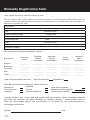
Warranty and Warranty
Registration Form
3
6
7
8
13
12
14
15
16
17
4 5
-
9
10
11
18
19
20
21
22
23
24
25
-
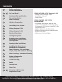
Contents
If these instructions are followed you should not have any problems during
installation. However, if you require assistance at any stage, please call our helpline :
US:1-888-927-6333 Canada:1-888-592-7687

3
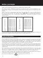
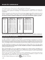
Thank you for purchasing the Warmup® NADWS Loose Heating Cable.
This manual contains IMPORTANT information regarding the safe use and installation of your
heating cable. Please read through the entire manual carefully before you install or use the
product.
Double check your measurements and ensure that you have the correct heating cable for
the area you wish to heat. The heating element MUST NOT be installed under appliances
or permanent fixtures such as refrigerators, cabinets,tubs, vanity units etc. Below is a quick
reference guide.
Area (sq ft)
10
15
20
25
30
40
50
60
75
90
110
120
120V Cables
NADWS-120-140
NADWS-120-210
NADWS-120-280
NADWS-120-350
NADWS-120-420
NADWS-120-560
NADWS-120-700
NADWS-120-840
NADWS-120-1050
NADWS-120-1260
NADWS-120-1540
NADWS-120-1620
Area (sq ft)
25
40
50
75
90
110
150
180
220
240
240V Cables
NADWS-240-350
NADWS-240-560
NADWS-240-700
NADWS-240-1050
NADWS-240-1260
NADWS-240-1540
NADWS-240-2100
NADWS-240-2520
NADWS-240-3080
NADWS-240-3240
If you are missing any items from the box or believe that you have the incorrect heaters to
cover the area required, please call the helpline for further assistance.
Product Information
The Warmup heating Cable consists of:
A twin conductor resistance heating cable with a primary insulation of Fluoropolymer with high
dielectric strength and high temperature properties. The conductors are covered by metallic
sheath providing additional mechanical strength and a ground path. A final outer jacket of
Fluoropolymer is given to make it sturdier and provide corrosion protection.
The heating cable is terminated at one end with a 10’ cold lead. The conductor cores and ground
braid are factory joined in a water resistant joint assembly to each supply conductor and ground
conductor of the unheated lead. The heater is terminated at the other end with a smaller water
resistant joint.
We recommend you do not alter the length of the unheated lead, however if necessary, the
wire can be extended using a suitable UL-approved wire and connector box. This must be
carried out by a qualified electrician in accordance with local/state laws and guidelines.
Inspect the entire heating cable for damage, this includes the factory made joint and end
termination. If any parts are damaged contact the technical helpline.
The Warmup Heating Cable is approved (File No. E303230).
Before you Begin

4
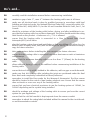
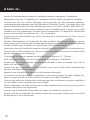
Do’s and...
DO carefully read this installation manual before commencing installation.
DO maintain a gap of min. 3”, max. 4” between the heating cable runs at all times.
DO make sure all electrical work is done by qualified persons in accordance with local
building and electrical codes, the National Electrical Code (NEC), especially article 424,
Part V of the NEC, ANSI/NFPA 70, for the US and Canadian Electrical Code, Part 1, for
Canada.
DO check the resistance of the heating cable before, during, and after installation to en-
sure that the heating cable has not been damaged. The value should match the rating
label found on the product. A tolerance of +/- 5% is allowed.
DO ensure that the heating cable is connected to a Class A Ground Fault Circuit
Interrupter(GFCI) at all times.
DO plan the heating system layout and installation so that any drilling after tiling (e.g. for
fixtures such as vanity units, tubs) will not damage the wiring. Remember to keep a
copy for future reference.
DO take some pictures before installing the floor covering for future reference.
DO ensure that the heating cable is separated from other heat sources such as luminaires
and chimneys.
DO ensure that the minimum bending radius is no less than 1” (25mm) for the heating
cable.
DO allow sufficient drying/curing of the subfloor before commencing installation of the
heating cable.
DO ensure that each tile is solidly bedded in tile adhesive, with no gaps or voids beneath.
DO make sure that ALL heating cable including the joints are positioned under the final
floor finish and completely embedded in thinset/adhesive.
DO remember to install the floor probe for the Warmup® thermostat. The floor sensor
should be located in the centre of two heating element runs. Ensure that the sensor
does not touch or cross over any of the heating cables.
DO ensure that you have electrical provisions to run the heating system at 120VAC /or
240VAC depending on the system being installed.
DO check the wattage and voltage of the heating cable to ensure you have the correct
system for your application.
DO ensure that the cold tail conduit is kept separate from the sensor conduit.
DO remember to attach the rating labels included within this manual to the circuit break-
er and thermostatics controls.

5
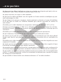
...Dont’s
DON’T allow the heating cables on the mat to cross over or touch each other at any point as
this can cause the cable to overheat. Always use the fixing strips to avoid this.
DON’T cut or shorten the heating cable at any time.
DON’T install the heating cables with any staples or other metal fixings that can damage the
heating cable.
DON’T store tiles, sharp or heavy objects on any of the wiring while tiling or bang a trowel
on the installation area to remove excess mortar from the trowel.
DON’T install the heating mat below 5°F (-15°C) ambient temperature.
DON’T attempt to bypass the GFCI if it trips and cannot be reset during normal operation.
Consult a qualified electrician or call the helpline for further assistance.
DON’T install the heating element under permanent fixtures.
DON’T commence installation on a mud job/screed that has not been fully cured.
DON`T
use the heating system until you have allowed sufficient drying period for the
finished floor.
DON’T cover the cold lead joint or termination joint with tape when securing the subfloor.
This may cause air pockets resulting in the joints overheating.
DON’T install the heating mat beyond the room or area in which they originate.
DON’T attempt to repair the heating cable if it becomes damaged. Call the technical helpline
for further instructions.
DON`T allow the thermostat to exceed the maximum temperature for your final floor
finish. Always check the maximum temperatures allowed with the floor covering
manufacturer.
DON’T switch on the installed heating system until tile adhesive has fully cured (1 - 3 weeks
minimum), check adhesive manufacturer’s instructions.
DON’T install the cold leads closer than 2” from the heating cable on the mat.

6
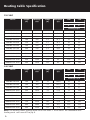
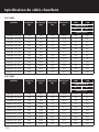
120 VOLT
Model Length
(ft)
Wattage
(W)
Amps
(A)
Resistance
(Ω)
14W 11W
Cable Spacing
3” 4”
Coverage sq ft
NADWS-120-140 40 140 1.2 102.9 10 13
NADWS-120-210 60 210 1.8 68.6 15 20
NADWS-120-280 80 280 2.3 51.4 20 27
NADWS-120-350 100 350 2.9 41.1 25 33
NADWS-120-420 120 420 3.5 34.3 30 40
NADWS-120-560 160 560 4.7 25.7 40 53
NADWS-120-700 200 700 5.8 20.6 50 67
NADWS-120-840 240 840 7.0 17.1 60 80
NADWS-120-1050 300 1050 8.8 13.7 75 100
NADWS-120-1260 360 1260 10.5 11.4 90 120
NADWS-120-1540 440 1540 12.8 9.4 110 147
NADWS-120-1620 480 1620 13.5 8.9 120 160
240 VOLT
Model Length
(ft)
Wattage
(W)
Amps
(A)
Resistance
(Ω)
14W 11W
Cable Spacing
3” 4”
Coverage sq ft
NADWS-240-350 100 350 1.5 164.6 25 33
NADWS-240-560 160 560 2.3 102.9 40 53
NADWS-240-700 200 700 2.9 82.3 50 67
NADWS-240-1050 300 1050 4.4 54.9 75 100
NADWS-240-1260 360 1260 5.3 45.7 90 120
NADWS-240-1540 440 1540 6.4 37.4 110 147
NADWS-240-2100 600 2100 8.8 27.4 150 200
NADWS-240-2520 720 2520 10.5 22.9 180 240
NADWS-240-3080 880 3080 12.8 18.7 220 293
NADWS-240-3240 960 3240 13.5 17.8 240 320
Note: The heating cables spacing must be no less than 3” at all times. The maximum area
loading must not exceed 15w/sq ft.
Heating Cable Specification

7
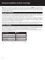
Note: The UL Listing for this product covers use in wet locations for CANADA only. Wet location
installation in United States shall be in accordance with the National Electric Code, NFPA 70 and
any other applicable jurisdictional code and final acceptance is to be made by the Authority
having Jurisdiction (AHJ).
Thermal Insulation
The insulation levels of a floor will affect both the performance & running costs of under tile
heating. Using the heating cable without thermal insulation can take up to 5 hours to heat a
room whereas a system with thermal insulation takes less than an hour.
If the Warmup heating cable is being installed onto a concrete base it is highly recommended
that a layer of insulation is used prior to installing the heating cable. The thermal insulation
reflects the heat upwards instead of allowing heat to penetrate into the subfloor, greatly
improving the warm-up times & running costs.
The Warmup insulation boards are fixed to the base using screws or tile adhesive. The thickness
of insulation required will depend on whether it is for floor renovation or a new floor.
Floor coverings
All floor finishes should be installed as per the manufacturer´s instructions. With radiant heat-
ing, the floor covering is essentially part of the heating system. The most suitable floor cover-
ings are those with a low thermal resistance, normally referred to as the R-value.
The Type and thickness of floor covering materials used with this product must not exceed a
thermal insulation “R” value of 1.
Floor covering R Value
Carpet 1.0
Ceramic, Mosaic Tile 0.15
Laminate Flooring 0.675
Natural Stone 0.38 - 0.114
Wood Flooring 0.80
Thermal Insulation & Floor Coverings

8
Ensure that the subfloor is smooth, dry and free from dust. Visually check that there are no
objects on the floor that might damage the heating mat.
Where necessary an appropriate smoothing compound should be applied and allowed to cure.
If the cable is being fitted to a solid floor it is essential that the concrete slab has been allowed
to cure.
If using the Warmup insulation boards use a suitable cement based adhesive and screws to fix
boards to the subfloor as per the instructions.
If installing in a wet room ensure a slope in the mortar bed is maintained in order to direct
water to the drain pipe.
Subfloor Preparation

9
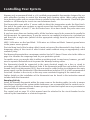
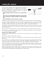
Warmup only recommends listed or c-UL certified programmable thermostats designed for use
with underfloor heating to control the Warmup loose heating cables. When using multiple
loose heating cables you can connect them in parallel to the same thermostat. Check with your
installer or call Warmup for circuit sizes and maximum loads.
The thermostats come with a 9’ sensor cable to detect the temperature under the floor finish.
The end of the probe wire contains a capped sensor that should be evenly centered between
two heating cables at least 12” into the heated area. At no time should the probe wire cross
the heating cable.
If you have more than one heating cable, all the lead wires need to be connected in parallel to
the thermostat. For convenience, it may be easier to run multiple lead wires to a junction box
and then take a single wire (which has the appropriate rating) from the junction box to the
thermostat.
NOTE: 240V wires are Red and Black. 120V wires are Yellow and Black. Connect ground wires
to the power source ground.
The total Amp load of the heating cable(s) must not exceed the thermostat’s Amp limit or the
Amperage rating of the circuit or other control switch without using an appropriately rated
contactor/relay.
The Warmup thermostat has a maximum resistive load of 15 Amps. Please refer to the table on
page 6 to calculate the amperage load for your particular system.
For smaller areas, you may be able to utilize an existing circuit. In most cases, however, you will
need a separate dedicated circuit to power the Warmup heating cables.
The thermostat should be connected to the main electrical supply via a fuse or circuit in
accordance with the National Electrical Code. If the thermostat used does not include a built-in
Ground Fault Circuit Interrupter (GFCI), then one must be added to the circuit between the main
power supply and the thermostat. If the thermostat does include a GFCI, it is NOT recommended
to include another in the circuit, as this may cause accidental tripping of the control unit.
Further details on the installation of the thermostat can be found in the instruction manual
included with the thermostat.
Ensuring Safety
Install the Warmup thermostat within the same room as the heating cables. In order to ensure
the efficient running of the system within bathrooms, we recommend that the controls are lo-
cated at least 60 inches away from shower openings or basin back splash areas so you minimize
the possibility of exposure to water.
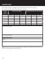
The control card on page 22 of this manual must be attached to the circuit breaker box for
referral by the homeowner or electrical inspector.
Controlling Your System

10
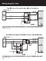
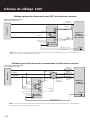
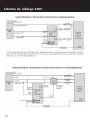
Wiring Diagram 120V
Canadian Electrical Code, part 1 in Canada or the National Electrical Code in the USA, especially Article 424, Part V
of the NEC ANSIINFPA 70.
Canadian Electrical Code, part 1 in Canada or the National Electrical Code in the USA, especially Article 424, Part V
of the NEC ANSIINFPA 70.
CSA/CEC or NEC
CSA/CEC or NEC
(green/bare)
(green/yellow)
(yellow)
(green/yellow)
(yellow)
Live (black)
Neutral (white)
Live (black)
Neutral (white)
12
12
110 -
120V
Max 15 amps

11
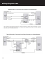
Wiring Diagram 240V

12
For each Warmup loose heating cable you install, you will have 1 unheated lead running from
the floor to the thermostat’s electric connection. The joint connecting the unheated lead to the
heating cable must be at least 2 inches from the wall and placed in a position to be covered by
a thinset/adhesive under the final floor covering. THIS JOINT SECTION MUST NEVER BE PLACED
IN THE DRYWALL.
It may be necessary to chisel out short channels in the subfloor to minimize the increased
height presented by the floor probe and the unheated lead.
Neither the unheated lead nor sensor wire must cross, or come into contact with the heating
element. Bear in mind that you will need to make provisions for drawing the unheated lead and
sensor wire up through the conduit to the control box.
NOTE: Local electrical code my require that cold leads be protected where they leave the floor,
by rigid metal conduit, intermediate metal conduit, rigid non metallic conduit, electrical metallic
tubing or by other approved means. Please refer to local electrical codes for further information.
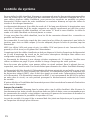
The installation of electrical systems presents risks of fire and electrical shock which can result
in personal injury. Caution should always be taken to guard against each such risk. All electrical
connections should be carried out by a qualified electrician in accordance with the National
Electrical Code and all local Codes. For installations in Canada, refer to sections 12 and 62 of
the CEC.
The Warmup loose heating cables MUST be connected to the electrical system through a
Ground Fault Circuit Interrupter (“GFCI”). If you are not using a thermostat with a built in GFCI,
ensure that the branch circuits that supply your panels are GFCI-protected, or, if possible, a
dedicated GFCI is incorporated in each circuit supplying your panels. This requirement is critical
to the safe operation of your Warmup loose heating cables.
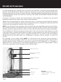
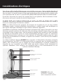
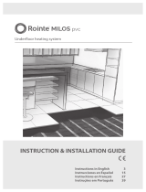
Electrical Provisions
ALWAYS use listed
conduit, fittings and other
components.
Conduit to power source
Electrical box for connection to
the thermostat
Conduit for heating cable
cold lead.
Conduit for floor sensor
Heating cable
Floor Sensor

13
Each and every Warmup loose heating cable is subjected
to careful testing before it is shipped from the factory.
However, damage does sometimes occur in storage or
transit, and sometimes during installation. We strongly
recommend you test your heaters:
After unpacking them but before you install them,
and
After you have installed them but before you install the
floor covering (i.e. while the cables are still exposed),
and
After installation of the final floor covering.
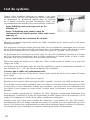
Complete a simple visual inspection of the heating cable to make sure there is no visible damage.
A simple electrical inspection can be done with a digital ohmmeter to ensure the ohms
resistance is what it should be. The ohm resistance should be measured between the two
conductors without touching the yellow-green wire, which is the ground connection.
Checking for resistance between the two conductor wires ensures there is no break in the cold
lead conductor and the heat resistance wire. It does not assure you that there is no electrical
short in the circuit.
Place one probe on the black wire. Place the other probe on the yellow (red wire for 240V).
Resistance can vary significantly depending on the ambient temperature and an allowance of
+/- 5% from the norm is acceptable.
Ensure cable is fully insulated :
Test across the yellow-green wire (ground). Place the other probe on the yellow (red wire
for 240V ).
Confirm the reading is infinity (open circuit).
Repeat these steps to check the reading between the yellow-green wire (ground) and the
black wire.
There should be no continuity between these wires and the ohms reading should be infinity
(not zero). If your meter shows a value of less than 200MOhms between these wires, your
heating cable has an electrical short. Take note of the resistance and contact Warmup.
In order to conduct a more thorough test for insulation verification, Warmup recommends the
use of a megohmeter. Connect the instrument’s black cable to the system’s ground and the
red to the either one of the heating cable leads.
Note that depending on your meter model, you may read “kilo-Ohms” probably due to your
fingers touching the probes (it’s your body’s conductivity). If the readings are not satisfactory,
do not commence installation contact Warmup for further advice.
Testing the System

14
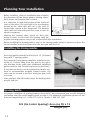
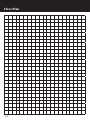
Before installing, draw an installation plan showing
the placement of the fixings guides, heating cables,
floor sensor, and junction box or boxes.
It is important to mark the location of the cold lead
joint on the plans. The cold lead is the non-heating
portion of the cable that will run in the wall to
connect the system to the thermostat. The heating
cable shall not extend beyond the room or area in
which it originates.
Marking the heating cable layout on floor plan
makes it easier to trace back the heating cable for
trouble shooting purpose. Keep such a layout filed after installation.
Before installing the heating cables, refer to the spacing guide below to ensure you have the
correct number and size of heaters for the area you wish to heat.
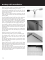
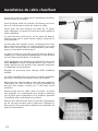
Installing the Fixing Guides
The fixing guides included in the kit are 12” (300mm)
long with 1” spacing guides.
The perimeter fixing guides should be installed a min-
imum of 3 inches away from the wall in the oppo-
site direction to the cable runs (Additional stabilizing
guides could be laid 40 inches apart across the floor).
It may be necessary to cut the guides into smaller sec-
tions to accommodate irregular shaped rooms. The
strips can be secured to the floor using hot glue, nails
or screws.
Once you have fitted the cable strips, the heating cable
may be laid out.
Spacing Guide
For precise calculation of spacing between loops (OCS), we recommend you use the following
calculation using the cable lengths given on page 6. For additional clarification please call our
technical support line: US: 1-888-927-6333 or Canada: 1-888-592-7687
OCS (On Center Spacing)=Area (sq ft) x 12
Length (ft)
Planning Your Installation

15
Before you start laying the underfloor heating cable
ensure that the heating cable(s) are tested.
Gently pull the unheated lead from the box. Do not
remove the spool from the box as this will cause the
heating cable to twist.
After 10 feet of cable has been removed, you will
reach the point at which the unheated lead joins the
heating cable.
The joint should be taped to the floor at the start point.
Ensure that the factory joint lays flat on the floor.
The joint must be installed under the floor covering
and covered with mortar or self-levelling underlay-
ment. A channel will need to be made into the sub-
floor to accommodate the extra height of the joint.
Care should be taken to ensure that the joint is not
bent at the point of entry into the conduit as this may
damage both the factory joint and/or the heating ele-
ment within.
Secure the joint to the floor using a piece of duct tape
over the cable before and after the joint, but not over
the joint itself.
Repeat this process for each heater installed.
Install the heating cable as per the installation plan.
The heating cable should be laid in parallel lines
back and forth across the main body of the area to
be heated.
Use the spacing guide on page 14 to space the cable.
The heating cable must not be spaced out any closer
than 3” at any time.
Ensure that the cable is held in place by the fixing
guides and that you maintain moderate tension on the
cable to prevent it from lifting during the installation
of the final floor covering.
Using duct tape secure the end joint to the floor by
taping the heating cable in place just before the joint.
Do not cover the joint in tape as air pockets may cause
the end joint to overheat.
Heating Cable Installation

16
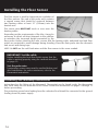
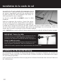
Installing the Floor Sensor
The floor sensor is used for temperature regulation of
the floor surface. The end of the probe wire contains
a capped sensor that should be centered between
two heating cables at least 12” (305mm) into the
heated area.
The sensor wire MUST NOT touch or cross over the
heating cables.
Depending on the requirements of the tiler, it may be
necessary to chisel out short channels in the subfloor
to minimize the increased height presented by the
floor probe. Before chiseling the area, ensure that the heating cable, unheated lead and floor
probe are protected to avoid damage during chiseling. Place the floor probe into the channels
and secure with fixing tape.
NOTE: Do NOT run the cold lead wires and the floor sensor in the same conduit.
Installing the Warmup Thermostat
Instructions for the fitting of the Warmup® Thermostat can be found inside the thermostat
box. Each cable has one unheated lead. Please review the information on pages 9 through 12
before proceeding.
The protective ground wire leading from the unheated lead should be connected to the ground
leading from the power supply.
IMPORTANT! Test the cable
Before installing the final floor finish ensure that the
cable is working properly using the method described
on page 13.
Test the probe wire:
Temperature sensor wire must be verified before and
after installation. For probe resistances, refer to the
thermostat instructions.

17
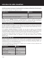
When installing the heating cable under tile or stone flooring choose one of the following methods:
1. Single Layer Method:
Apply a layer of 3/8” modified thinset cement or adhesive over the heating Cable.
Lay the tile or stone directly into that layer of thinset cement.
2. Double Layer Method:
Embed the heating Cable in a skim coat of self-leveling compound completely covering the
heating element and the sensor wire. Using a rubber float spread the thin-set over the mat in
the same direction as the cable. Ensure that the space between the cable is filled. Allow this
layer to dry completely.
Apply a second layer of thinset or adhesive and lay the tiles as usual. The required minimum
total for both layers is 3/8” of thinset or adhesive.
When deciding between the single layer or the double layer method you should consider the
following:
We do NOT recommend the single layer method if you will install mosaics or a combination of
tiles of different sizes.
If this is the first time installing underfloor heating the double layer method is highly
recommended.
Waiting Period: Ceramic tiles and stone installations require 1 to 3 weeks for the thinset
to cure. Do not switch on the underfloor heating system until you have allowed the thinset
material to fully cure. Failure to do so will result in damage to the system and cause the thinset
to become brittle.
Carpet, Vinyl or Laminate Flooring
Embed the heating cable in a layer of self-leveling compound and let it dry. Ensure that the
heating cable are covered with a minimum of 3/8” of self-leveling compound.
Note : The under floor heating cables are NOT approved for direct contact with combustible
material. The heating cable MUST always be embedded in thinset / cement mortar / cement
based adhesive glue / tile adhesive before installing floating wood or laminate floors.
Floor Coverings - Tiles & Stone

18
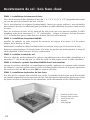
STEP 1: Wooden Sleepers/ Strips Installation:
Fix the wood sleepers (strips of wood 1” x 1” to 2” x 3/8” to 1/2”) perpendicular to the
planned direction of hardwood board.
On the plywood subfloor leave a sufficient space at the end of each wooden sleeper to allow
the cable to go from one section to the other.
The sleepers are fixed in such a manner that they create a gap between 12-16” between two
sleepers in which the heating cable can be installed. Cut approx ½“ sleeper, whenever the cable
is to be carried over to the next sleeper bay.
STEP 2: NADWS System Installation:
Install the Fixing Strip, ensure that you maintain at least 3/4 inches gap from the wood sleepers.
Now Install the cable into the gap which was created by the sleepers.
Carefully return the cold tail lead to the junction box or the thermostat alongside the heating
cable and wooden sleepers, if required.
STEP 3: Install the floor sensor
Place the probe wire containing the capped sensor evenly between two heating cables loops
at least 12” (30.48cm) from the wall into the heated area. At no time should the probe wire
cross the heating cable.
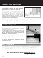
STEP 4: Covering of the NADWS cable system
Once the cable(s) have been laid, the system should be covered by self-leveling or dry-pack
compound up to the sleeper’s height. Do Not cover the sleepers.
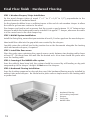
STEP 4: Hardwood Flooring Installation:
Once the leveling compound or dry-pack has cured, the hardwood flooring may be installed by
nailing it into wood sleepers. Be careful not to place nails or staples near to the heating cable
or power lead.
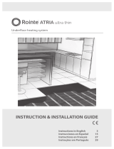
Final Floor finish - Hardwood Flooring
1
2
3
4
5
1. Hardwood Flooring
2. Self-Leveling Compound
3. Sleepers
4. Fixing Strip
5. NADWS Cable

19
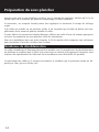
Ensure that there are no air gaps during application of the cement/mortar cement based
adhesive/tile adhesive/thinset or self-leveling compound.
Ensure the entire heating cable, factory splices and thermostat floor sensor are embedded in
the cement mortar. The choice and application of building materials should be in accordance
with building materials manufacturer’s instructions.
Ensure that the correct maturity and curing times for drying of construction materials is
followed before you powering ON the heating cables.
Test the heaters before, during and after installation of the final floor finish. Record values in
the control card on page 22 of this manual.
Operating Tips
When first energized, the under tile heating cables may take up to 3 hours to fully warm
your floor.
Energy consumption will vary depending on user preferences. For lower energy consumption
set the thermostats to optimum temperature setting.
Energy consumption can be minimized by turning the system OFF when floor heat is not
required, but you will have to allow time for the floor to warm up once the system is turned
‘ON’ again.
We recommend and supply Thermostats with “set-back” option. This option will reduce the
heat-up time to less than 1 hour by reducing the floor temperature and not actually turning off
the system during the setback period(s).
Avoid placing thick mats / rugs / floor level furniture / mattresses on your heated floor,
specially in the area where the sensor of a floor-sensing thermostat is located. These restrict
the transfer of heat away from the cables and result in the floor area beneath them being
warmer than other areas.
Avoid mats with rubber or vinyl type backing, as these may decompose with heat and could
stain flooring.
Points to Remember

20
CAUTION: TURN OFF THE POWER SUPPLY BEFORE TROUBLESHOOTING
If the system fails to heat, check that the GFCI (Ground Fault Circuit Interrupter) has not been
tripped. If the GFCI has tripped on the thermostat, this will be indicated with red “test” light on
the thermostat. If the thermostat does not have a GFCI, check that the GFI on the breaker panel
has not tripped. Check for continuity and resistance level with an ohmmeter and compare
the reading with the resistance recorded on the UL label. Make sure the breaker or fuse is
delivering power to the system. If the system fails to heat after these checks, call your installer
or Warmup®. You will need to locate the model information for the heater, either on the
product labels you kept, or based on an invoice. While incorrect grounding is the main cause
for breaker tripping, please contact your installer to review your installation more in detail.
CHECKING FOR BREAKS
Checking for resistance between the two conductor wires ensures there is no break in the cold
lead conductor and the heating cable wire.
CHECKING FOR ELECTRICAL SHORT
In some rare instances, a sharp object can puncture the insulation around the heating
cable, thereby allowing the electricity to flow to ground. If this situation occurred it would
immediately trip the GFCI (Ground Fault Circuit Interrupter).
Follow the steps on page 13 if the readings are not satisfactory, contact Warmup® for
further advice.
Troubleshooting
La page charge ...
La page charge ...
La page charge ...
La page charge ...
La page charge ...
La page charge ...
La page charge ...
La page charge ...
La page charge ...
La page charge ...
La page charge ...
La page charge ...
La page charge ...
La page charge ...
La page charge ...
La page charge ...
La page charge ...
La page charge ...
La page charge ...
La page charge ...
La page charge ...
La page charge ...
La page charge ...
La page charge ...
La page charge ...
La page charge ...
La page charge ...
La page charge ...
La page charge ...
La page charge ...
La page charge ...
La page charge ...
-
 1
1
-
 2
2
-
 3
3
-
 4
4
-
 5
5
-
 6
6
-
 7
7
-
 8
8
-
 9
9
-
 10
10
-
 11
11
-
 12
12
-
 13
13
-
 14
14
-
 15
15
-
 16
16
-
 17
17
-
 18
18
-
 19
19
-
 20
20
-
 21
21
-
 22
22
-
 23
23
-
 24
24
-
 25
25
-
 26
26
-
 27
27
-
 28
28
-
 29
29
-
 30
30
-
 31
31
-
 32
32
-
 33
33
-
 34
34
-
 35
35
-
 36
36
-
 37
37
-
 38
38
-
 39
39
-
 40
40
-
 41
41
-
 42
42
-
 43
43
-
 44
44
-
 45
45
-
 46
46
-
 47
47
-
 48
48
-
 49
49
-
 50
50
-
 51
51
-
 52
52


Warmup Loose Wire – NADWS Guide d'installation
- Taper
- Guide d'installation
dans d''autres langues
Documents connexes
Autres documents
-
 SCS Sentinel 3245060930943 Le manuel du propriétaire
-
 SCS Sentinel 3245060930929 Le manuel du propriétaire
-
 SCS Sentinel 3245060930905 Le manuel du propriétaire
-
eModernDecor ASD-4-SQ Guide d'installation
-
SunTouch Floor Warming 12000830R Mode d'emploi
-
 Rointe Cabo de aquecimento para pisos duros Bekia Le manuel du propriétaire
-
 Rointe Milos Le manuel du propriétaire
-
 Rointe Atria Le manuel du propriétaire
-
resideo S8910U3000 Guide d'installation
-
Rointe Malla de aquecimento para pisos laminados, vinil, linóleo e alcatifa Erko Le manuel du propriétaire


