
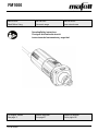
FM1000
170758.0822/b
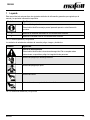
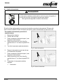
IMPORTANT
Read Before Using
IMPORTANT
Lire avant usage
IMPORTANTE
Leer antes de usar
Operating/Safety Instructions
Consignes d’utilisation/de sécurité
Instrucciones de funcionamiento y seguridad
For English Version
See page 2
Version française
Voir page 21
Versión en español
Ver la página 40

FM1000
2
08/2022
English
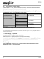
Table of contents
1 Signs and symbols ........................................................................................................... 3
1.1 Identification of the device ................................................................................................ 5
2 Product specifications ...................................................................................................... 6
2.1 Technical data .................................................................................................................. 6
2.2 Scope of delivery .............................................................................................................. 7
2.3 Adjustment elements ........................................................................................................ 7
3 General safety .................................................................................................................. 8
3.1 Intended use ..................................................................................................................... 8
3.2 Foreseeable misuse ......................................................................................................... 8
3.3 Safety instructions ............................................................................................................ 9
3.4 Specific safety rules ....................................................................................................... 10
3.5 Safety devices ................................................................................................................ 11
3.6 Residual risks ................................................................................................................. 12
4 Setup / adjustment ......................................................................................................... 12
4.1 Mains connection ........................................................................................................... 12
4.2 Tool selection ................................................................................................................. 12
4.3 Collet chucks .................................................................................................................. 13
4.4 Tool change .................................................................................................................... 15
5 Operation ........................................................................................................................ 16
5.1 Startup ............................................................................................................................ 16
5.2 Switching on / off ............................................................................................................ 16
5.3 Speed selection .............................................................................................................. 17
5.4 Overload protection ........................................................................................................ 17
6 Service and maintenance ............................................................................................... 18
6.1 Storage ........................................................................................................................... 18
7 Troubleshooting .............................................................................................................. 19
8 Optional accessories ...................................................................................................... 20
9 Exploded view and spare parts list ................................................................................. 20

FM1000
08/2022
3
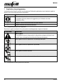
1 Signs and symbols
These operating instructions contain the following general information signs to guide you, the reader, through
the operating instructions and to provide you with important information.
Sign
Meaning
Important information
This sign highlights user tips and other useful information.
➢
Identifies an intermediate result in a sequence of actions.
✓
Identifies the final result of a sequence of actions.
Tab. 1: General signs and their meanings
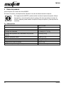
Warning icons warn of dangerous points, risks and obstacles.
Icon
Meaning
Warning
This icon can be found at all locations where you can find information regarding your
safety. Non-observance can result in extremely serious injuries.
Warns of danger of electric shock.
Warns of danger caused by dust.
Warns of the danger of cutting.
Warns of the danger of cutting off or severing limbs.
Tab. 2: Warning icons and their meanings

FM1000
4
08/2022
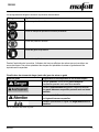
Mandatory icons are intended to prevent accidents.
Icon
Meaning
Wear eye protection.
Wear dust mask.
Wear hearing protection.
Wear protective gloves.
Tab. 3: Mandatory icons and their meanings
During the operation of the power tool there are always actions to be taken where hazards can occur. These
potentially dangerous actions are preceded by warnings which must be observed.
Classification of the danger level (signal words) of warnings
Warning
Meaning and consequences of non-observance
Imminent dangerous situation that will cause serious or
fatal injuries.
Potentially dangerous situation that can cause serious or
fatal injuries.
Potentially dangerous situation that can cause light
injuries.
Situation that can cause material damage on the machine
Tab. 4: Structure of warnings

FM1000
08/2022
5
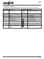
1.1 Identification of the device
The icons listed and explained below can be found on the rating plate or on the product.
Icon
Explanation
Icon
Explanation
V
Volt
1, 2, 3, ...
I, II, III, ...
Rotational speed setting
A
Ampere
rpm
Revolutions per minute
Hz
Hertz
ø
Tool diameter
W
Watt
~
Alternating current
kg
Kilogram (weight)
Protection class II
min
Minutes (time)
Read operating instructions
s
Seconds (time)
Protective goggles
n0
Rated speed at no load
Hearing protection
n
Rated speed at normal load
Dust mask

FM1000
6
08/2022
2 Product specifications
for machines with item number 9M0023
The article number and machine number are listed on the type plate of the machine.
By entering the article number and machine number on the MAFELL homepage, you can
call up the spare parts lists, exploded drawings, and other product information belonging
to your machine (see also Chapter 9 Exploded view and spare parts list).
2.1 Technical data
Operating voltage
120 V~, 60 Hz
Current at normal load
8.3 A
Tool speed at no load
10000 to 25000 rpm
Tool shaft
3 - 8 mm [0.12 - 0.32 in]
Diameter of tool holding fixture with collet chuck
6.35 mm [0.25 in]
Grinding tool diameter
40 mm [1.57 in]
Milling cutter diameter
36 mm [1.42 in]
Weight without power cord
1,6 kg [3.53 lbs]
Length of the connecting cable
4 m [13.12 ft]
Dimensions (width x length x height)
73 x 254 x 79 mm [2.87 x 10 x 3.11 in]

FM1000
08/2022
7
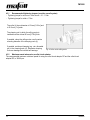
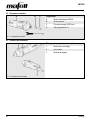
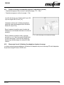
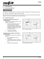
2.2 Scope of delivery
Fig. 1: Scope of delivery
Components
A
Milling motor FM1000
B
Union nut
C
Collet chuck OZ ø 8 mm [0.31 in]
D
17-mm [0.67 in] single open-end wrench
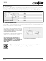
2.3 Adjustment elements
Fig. 2: Adjustment elements
Adjustment elements on the machine
1
Locking button
2
Power switch
3
Setting wheel

FM1000
8
08/2022
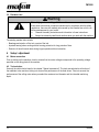
3 General safety
Please read all safety instructions and directions. Failure to comply with the safety instructions and
directions can cause electric shock, fire and/or serious injuries. Please retain all safety instructions and
directions for future reference.
3.1 Intended use
The milling motor is intended for stationary installation in a guiding gantry system with a collar size of ø 43 mm
[1.69 in].
Intended use also requires the guiding gantry system to be included.
The milling motor can be operated with cutter diameters that are compatible with the collet chucks listed in the
special accessories. Wood, plastic and non-ferrous metals can be machined. The cutting data must be
selected such that the motor is not overloaded.
3.2 Foreseeable misuse
The machine is not intended for any other use than the intended use listed above.
The manufacturer is not liable for any damage resulting from such other use.
To use the machine as intended, comply with the operating, maintenance and repair conditions specified by
MAFELL.
Foreseeable misuse also includes:
- Tampering with, removing and/or bypassing safety devices of any kind.
- Operating the machine without safety devices.
- Non-observance of safety and warning instructions in the operating instructions.
- Removing the safety and warning labels from the machine.
- Operating the machine by unauthorized persons.
- Failure to follow prescribed maintenance and care instructions.
- Machining with excessive cutting depth or feed rate due to excessive motor load.
- Using the machine in continuous industrial operation.
- Using the machine as a hand-guided milling motor.
Never use:
- Damaged and/or deformed tools.
- Blunt drill bits as they impose an excessive load on the motor.
- Tools that are not suitable for the no-load speed of the milling motor.

FM1000
08/2022
9
3.3 Safety instructions
READ ALL INSTRUCTIONS!
Non-observance of the instructions listed below can cause electric shock, fire and/or serious injuries
.
Work area
- Children and adolescents are not allowed to operate this machine.
- Replace damaged cables or plugs immediately. To avoid safety hazards, only MAFELL or an authorized
MAFELL service workshop is allowed to replace parts.
- Prevent sharp kinks of the cable. Do not wrap the cable around the machine, especially when transporting
and storing the machine.
- Do not use this machine when you are tired, or under the influence of drugs, alcohol or medicaments. Be
aware of what you are doing. Stay alert and use common sense.
- Keep children and bystanders at a distance while you are operating the machine. Distractions can cause
you to lose control of the machine.
- Use eye protection, dust mask and hearing protection. Appropriate safety equipment, used
under proper conditions, will reduce the risk of injuries.
Instructions for service and maintenance:
- Cleaning the machine regularly, especially the adjustment elements and the guiding devices, is an important
safety factor.
- Ensure that only genuine MAFELL spare parts and accessories are used. Failure to do so will make
warranty claims and the liability of the manufacturer null and void.
- Prepare a periodic maintenance schedule for your machine. When you clean the machine, be careful
not to disassemble any part of the machine. Reassembling the machine bears the risk that internal
wires are routed incorrectly or pinched, or that return springs of the safety device are mounted
incorrectly. Certain cleaning agents, such as gasoline, carbon tetrachloride, ammonia, etc. can damage
plastic parts.
- Some of the dust produced by sawing, sanding, drilling and other building work contains chemicals
known to cause cancer, birth defects or other reproductive harm. Some examples of these
chemicals are:
- Lead from lead-based paints,
- Crystalline silica from bricks and cement and other masonry products,
- Arsenic and chromium from chemically treated wood.
Your risk from this hazard varies with the frequency at which you perform this type of work. To reduce your
exposure to these chemicals: Work in a well-ventilated area. Work only with approved safety equipment,
such as dust masks that are specially designed to filter out particles of microscopic size.

FM1000
10
08/2022
3.4 Specific safety rules
Operation information:
- Never work without the protection devices of the gantry system in which the milling motor is inserted, which
are required for the respective operation.
- Do not change anything on the gantry system or the milling motor that could affect the safety.
- Using the unit in conjunction with water or conductive liquids is prohibited.
- Keep the milling motor away from rain or wetness. The ingress of water into the milling motor increases the
risk of an electric shock.
- Keep your hands away from the danger zone of the tool.
- Check the workpiece for foreign bodies.
- Watch the rotational speed. Switch off the power supply immediately if the rotational speed rises
uncontrollably or suddenly.
RETAIN THESE INSTRUCTIONS!

FM1000
08/2022
11
3.5 Safety devices
Danger
Risk of injury from missing safety devices
These devices are necessary for the safe operation of the machine. They must
not be removed or rendered ineffective.
➢ Check the proper functioning of the safety devices before you start
operating the machine.
➢ Never use the machine with missing or ineffective safety devices.
The machine is equipped with the following safety devices:
Safety device
Type of check
Stable collar for installation in stationary machines
Visual check for damage
Plastic housing to protect against electric shock
Visual check for damage
Stable connecting cable to protect against electric
shock
Visual check for kinks and incisions
Switching device
Functional check (coasting time must not exceed
5 seconds)
Warning lamp for rotating tool
Visual check for damage
If the safety devices are damaged or not functioning properly, follow the instructions in the chapter
Troubleshooting. For other malfunctions, please contact your dealer or MAFELL Customer Service directly.

FM1000
12
08/2022
3.6 Residual risks
Warning
Risk of injury when working with the machine
Even when the machine is used as intended and in compliance with the safety
regulations, there are still residual risks caused by the intended use, which can
have consequences for your health.
➢ Observe the safety instructions and information in these instructions.
➢ Always be extremely careful and cautious when you work with the machine.
The existing residual risks include:
- Breakage and ejection of the tool or parts of the tool.
- Impaired hearing when working without hearing protection for long periods of time.
- Emission of harmful wood dusts during longer operation without extraction.
4 Setup / adjustment
4.1 Mains connection
Prior to starting up the machine, check to ensure that the mains voltage corresponds to the operating voltage
specified on the rating plate of the machine.
4.2 Tool selection
Use only the collet chucks listed in the chapter "Special accessories". The tools are selected as a function of
the materials to be machined, taking into account the performance of the feed drives. Take into account the
performance of the milling motor when you select the maximum tool diameter and the intended machining
depth.

FM1000
08/2022
13
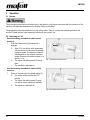
4.3 Collet chucks
Notice
Tightening the union nut excessively without an inserted tool can compress and thus damage the collet
chuck.
➢ Tighten the union nut only when a tool is inserted.
➢ To protect the thread, screw the union nut only lightly onto the milling spindle when there is no tool
inserted.
Information for using the collet chucks:
- Ensure that you use the correct cutter size for the collet chucks.
- To prevent the collet chucks from binding, oil them a little at the beginning and after prolonged use.
- To improve the concentricity, lightly grease the collet chucks or use a solid lubricant (for example Molykote
P-40).
- Using a square piece of wood or a rubber mallet (never a metal tool!), tap lightly from behind on the collet
chuck to loosen it if it is jammed.
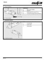
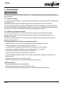
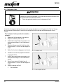
Use the following procedure to mount a collet
chuck:
1. Click the collet chuck into the union nut.
2. Screw the union nut onto the milling spindle.
✓ Collet chuck mounted.
Fig. 3: Mounting the collet chuck

FM1000
14
08/2022
4.3.1 Recommended tightening torques (consider overall system)
- Tightening torque for union nut / collet chuck = 10 - 11 Nm
- Tightening torque for collar = 7 Nm
The collar (4) has a diameter of 43 mm [1.69 in] and
is 25.5 mm [1 in] wide.
The clamping unit in which the milling motor is
installed must be at least 20 mm [0.79 in] thick.
If possible, clamp the milling motor over the entire
mounting diameter of the clamping neck (4).
If possible, avoid spot clamping (e.g. via a threaded
pin) in the clamping neck (4). Excessive clamping
force can damage the internal ball bearings.
Fig. 4: Collar on the milling motor
4.3.2 Maximum speed when using a collet chuck adapter
The recommended maximum rotational speed for using the collet chuck adapter OZ and the collet chuck
adapter ER, is 16000 rpm.

FM1000
08/2022
15
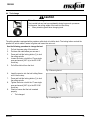
4.4 Tool change
Caution
Risk of burns/cutting
The inserted tool can heat up considerably during longer work processes.
Furthermore, the cutting edges of the insert tool are sharp.
➢ Wear protective gloves when changing tools.
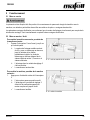
The milling spindle is equipped with a precision collet chuck to hold the tools. The locking button controls the
spindle lock, which makes it easier to tighten and loosen the union nut.
Use the following procedure to change the tool:
1. Pull out the power plug of the machine.
2. Put down the cable where you can see it.
3. Press and hold the locking button (1) to lock
the milling spindle.
4. Loosen the union nut with the 17-mm single
open-end wrench [0.67 in] or the ER 16 M
chuck key.
5. Pull off the old tool from the front.
Fig. 5: Removing the tool
6. Insert the new too into the tool holding fixture
until it hits the stop.
7. Press and hold the locking button (1) to lock
the milling spindle.
8. Tighten the union nut with the 17-mm single
open-end wrench [0.67 in] or the ER 16 M
chuck key.
9. Check to ensure that the tool is seated
properly.
✓ Tool changed.
Fig. 6: Inserting the tool

FM1000
16
08/2022
5 Operation
5.1 Startup
These operating instructions must be brought to the attention of all persons entrusted with the operation of the
machine, with particular emphasis on the chapter "Safety instructions".
These operating instructions describe only the milling motor. They do not take the installation situation into
account. Please take any other operating instructions into account, too.
5.2 Switching on / off
Use the following procedure to switch on the
machine:
1. Push the power switch (2) forward until it
engages.
➢ After 0.2 s, the milling motor accelerates
with a soft start to the previously selected
rotational speed. The duration of the soft
start depends on the selected rotational
speed. At maximum rotational speed, it is
approx. 1.2 s.
➢ The light at the setting wheel (3) shines
blue.
✓ The machine is switched on.
Fig. 7: Switching the machine on
Use the following procedure to switch off the
machine:
1. Press on the rear end of the power switch (2).
➢ The power switch jumps to the OFF
position.
➢ The light at the setting wheel (3) goes
out and the motor coasts to a standstill.
✓ The machine is switched off.
Fig. 8: Switching the machine off

FM1000
08/2022
17
5.3 Speed selection
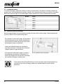
The setting wheel 3 permits a stepless change of the rotational speed. The concrete values of the rotational
speed of the individual steps can be found in the table below or on the rotational speed sticker on the housing.
The integrated electronics corrects to the selected rotational speed until the motor characteristic curve is
reached.
Fig. 9: Changing the rotational speed
Step
rpm
1
10000
2
13000
3
16000
4
19000
5
22000
6
25000
5.4 Overload protection
Overload during operation causes the milling tool to break, the workpiece to be damaged or even the milling
motor or gantry system to be damaged.
To protect the milling motor, the operating
parameters current, rotational speed and
temperature are monitored dynamically, and the
milling motor is switched off if necessary.
A short moment before the overload protection is
activated, the light at the setting wheel 3 changes to
permanent red.
To be able to restart the milling motor, switch the
circuit breaker (2) off and back on. The milling motor
becomes operational and the light at the setting
wheel (3) changes to blue.
Fig. 10: Overload protection
Prior to carrying out any work on the work spindle after the overload protection has been
activated, ensure that the mains plug is pulled out.

FM1000
18
08/2022
5.4.1 Visual output of the remaining running time
The visual output signals on the setting wheel (3) show the operating status. The lamp at the setting wheel
shines permanently blue as long as there is no overload on the milling motor.
If the milling motor is overloaded, the calculated remaining time is displayed as a red blinking code. The table
below shows the relationship between the blinking code and the related remaining runtime.
Operating mode
Remaining runtime in
seconds
Setting wheel - light
Continuous operation
Unlimited
Blue, permanent
Overload operation
(motor running)
< 160
1 x red pulse
< 80
< 40
2 x red pulse
< 20
< 10
3 x red pulse
< 5
Red, permanent
Shutdown
0
Table 5: Relationship between remaining running time and the related visual output signal at the setting wheel
If the remaining run time is not sufficient for your application, reduce the load or the feed rate to be able to
switch back to continuous operation.
6 Service and maintenance
MAFELL machines are of a low-maintenance design.
Have the carbon brushes replaced after a maximum of 125 to 150 operating hours.
The installed ball bearings are lubricated for life. After a longer period of operation, MAFELL recommends that
the machine be handed over to an authorized MAFELL service workshop for inspection.
6.1 Storage
Clean the machine thoroughly if you will not use it for quite some time. Spray bare metal parts with a rust
inhibitor.

FM1000
08/2022
19
7 Troubleshooting
Warning
Risk of injury from a sudden start of the machine.
There is a risk that the machine starts suddenly due to carelessness when
working with the machine or during troubleshooting. The rotating tool can cause
serious injuries.
➢ Determining the causes of existing malfunctions and their elimination
always require increased attention and caution!
➢ Pull out the mains plug before you start troubleshooting!
Some of the most common malfunctions and their causes are listed below. For other malfunctions, please
contact your dealer or MAFELL Customer Service directly.
Malfunction
Cause
Elimination
The milling motor cannot be
switched on. The lamp at the
setting wheel does not shine
Mains voltage missing or too low
Have the power supply checked
by an electrician
Mains fuse defective
Have the fuse replaced by an
electrician
The milling motor cannot be
switched on. The lamp at the
setting wheel shines blue
Carbon brushes worn out
Take the milling motor to the
MAFELL customer service
workshop
The milling motor stops during
operation. The lamp at the
setting wheel does not shine
Mains failure
Have the mains back-up fuses
checked by an electrician
The milling motor stops during
operation. The lamp at the
setting wheel shines red
Machine overload
Switch off the circuit-breaker.
Clear the work spindle before
starting up the machine. Switch
on the circuit breaker and
continue operation with less
load/feed rate

FM1000
20
08/2022
8 Optional accessories
- Collet chuck OZ8 ø 2 mm [0.08 in]
Order no. 093819
- Collet chuck OZ8 ø 3 mm [0.11 in]
Order no. 093812
- Collet chuck OZ8 ø 3.175 mm [0.125 in]
Order no. 093810
- Collet chuck OZ8 ø 4 mm [0.16 in]
Order no. 093813
- Collet chuck OZ8 ø 5 mm [0.20 in]
Order no. 093820
- Collet chuck OZ8 ø 6 mm [0.24 in]
Order no. 093814
- Collet chuck OZ8 ø 6.35 mm [0.25 in]
Order no. 093811
- Collet chuck OZ8 ø 8 mm [0.32 in]
Order no. 093815
- Collet chuck OZ8 ø 10 mm [0.40 in]
Order no. 093822
- Collet chuck OZ8 ø 3 mm [0.11 in] + union nut
Order no. 093816
- Collet chuck OZ8 ø 3.175 mm [0.125 in] + union nut
Order no. 093817
- Collet chuck ER 16 ø 3 mm [0.11 in]
Order no. 093753
- Collet chuck ER 16 ø 3.175 mm [0.125 in]
Order no. 093757
- Collet chuck ER 16 ø 4 mm [0.16 in]
Order no. 093754
- Collet chuck ER 16 ø 6 mm [0.24 in]
Order no. 093755
- Collet chuck ER 16 ø 6,35 mm [0.25 in]
Order no. 093760
- Collet chuck ER 16 ø 8 mm [0.32 in]
Order no. 093756
- Collet chuck ER 16 ø 10 mm [0.40 in]
Order no. 093759
- Union nut OZ
Order no. 093729
- Union nut ER 16 M
Order no. 093758
- Reducing sleeve ø 3 mm [0.11 in]
Order no. 207944
- Reducing sleeve ø 3,175 mm [0.125 in]
Order no. 207945
- Reducing sleeve ø 4 mm [0.16 in]
Order no. 207949
- Reducing sleeve ø 6 mm [0.24 in]
Order no. 207946
- Reducing sleeve ø 6,35 mm [0,25 in]
Order no. 207947
- Collet chuck adapter OZ incl. union nut OZ
Order no. 207943
- Collet chuck adapter ER 16 incl. union nut ER 16
Order no. 208109
- PV control cable M8 / 4-pol, 5 m [16.40 ft]
Order no. 208311
9 Exploded view and spare parts list
The corresponding information on the spare parts can be found on our homepage: www.mafell.com
La page est en cours de chargement...
La page est en cours de chargement...
La page est en cours de chargement...
La page est en cours de chargement...
La page est en cours de chargement...
La page est en cours de chargement...
La page est en cours de chargement...
La page est en cours de chargement...
La page est en cours de chargement...
La page est en cours de chargement...
La page est en cours de chargement...
La page est en cours de chargement...
La page est en cours de chargement...
La page est en cours de chargement...
La page est en cours de chargement...
La page est en cours de chargement...
La page est en cours de chargement...
La page est en cours de chargement...
La page est en cours de chargement...
La page est en cours de chargement...
La page est en cours de chargement...
La page est en cours de chargement...
La page est en cours de chargement...
La page est en cours de chargement...
La page est en cours de chargement...
La page est en cours de chargement...
La page est en cours de chargement...
La page est en cours de chargement...
La page est en cours de chargement...
La page est en cours de chargement...
La page est en cours de chargement...
La page est en cours de chargement...
La page est en cours de chargement...
La page est en cours de chargement...
La page est en cours de chargement...
La page est en cours de chargement...
La page est en cours de chargement...
La page est en cours de chargement...
-
 1
1
-
 2
2
-
 3
3
-
 4
4
-
 5
5
-
 6
6
-
 7
7
-
 8
8
-
 9
9
-
 10
10
-
 11
11
-
 12
12
-
 13
13
-
 14
14
-
 15
15
-
 16
16
-
 17
17
-
 18
18
-
 19
19
-
 20
20
-
 21
21
-
 22
22
-
 23
23
-
 24
24
-
 25
25
-
 26
26
-
 27
27
-
 28
28
-
 29
29
-
 30
30
-
 31
31
-
 32
32
-
 33
33
-
 34
34
-
 35
35
-
 36
36
-
 37
37
-
 38
38
-
 39
39
-
 40
40
-
 41
41
-
 42
42
-
 43
43
-
 44
44
-
 45
45
-
 46
46
-
 47
47
-
 48
48
-
 49
49
-
 50
50
-
 51
51
-
 52
52
-
 53
53
-
 54
54
-
 55
55
-
 56
56
-
 57
57
-
 58
58


dans d''autres langues
Documents connexes
Autres documents
-
Power Fist 8507667 Le manuel du propriétaire
-
Parkside PFBS 160 B2 Translation Of The Original Instructions
-
Metabo G 400 Mode d'emploi
-
Kress FM 6955 Le manuel du propriétaire
-
-
Parkside POF 1200 D3 Translation Of The Original Instructions
-
Parkside PFBS 160 A1 Operation and Safety Notes
-
Parkside POF 1200 C2 Translation Of The Original Instructions