
Robert Bosch Power Tools GmbH
70538 Stuttgart
GERMANY
www.bosch-pt.com
1 609 92A 58R (2020.03) T / 125
en Original instructions
fr Notice originale
ru Оригинальное руководство по
эксплуатации
uk Оригінальна інструкція з
експлуатації
kk Пайдалану нұсқаулығының
түпнұсқасы
ar
fa
1 609 92A 58R
GLL 2 Professional

2 |
English ................................................... Page 7
Français .................................................. Page 29
Русский............................................. Страница 45
Українська ...........................................Сторінка 63
Қазақ ..................................................... Бет 78
.................................................. 94
.................................................. 111
1 609 92A 58R | (04.03.2020) Bosch Power Tools

| 3
(1)
(2) (3)
(5)
(6)
(7)
(8)
(9)
(4)
Bosch Power Tools 1 609 92A 58R | (04.03.2020)

4 |
+
+
(10)
(11)
(12)
(13)
(4)
(15)
1 608 M00 05B
(14)
0 601 096 B00
BT 150
1 609 92A 58R | (04.03.2020) Bosch Power Tools

| 5
X XX
A
B
Bosch Power Tools 1 609 92A 58R | (04.03.2020)

6 |
C
D
1 609 92A 58R | (04.03.2020) Bosch Power Tools

English | 7
English
Safety Instructions
All instructions must be read and observed in order for
the measuring tool to function safely. The safeguards
integrated into the measuring tool may be comprom-
ised if the measuring tool is not used in accordance with
these instructions. Never make warning signs on the
measuring tool unrecognisable. SAVE THESE INSTRUCTIONS FOR FU-
TURE REFERENCE AND INCLUDE THEM WITH THE MEASURING TOOL
WHEN TRANSFERRING IT TO A THIRD PARTY.
u Warning! If operating or adjustment devices other than those spe-
cified here are used or other procedures are carried out, this can lead
to dangerous exposure to radiation.
u The measuring tool is delivered with a laser warning sign (marked in
the illustration of the measuring tool on the graphics page).
u If the text of the laser warning label is not in your national language,
stick the provided warning label in your national language over it be-
fore operating for the first time.
Do not direct the laser beam at persons or animals and
do not stare into the direct or reflected laser beam your-
self. You could blind somebody, cause accidents or damage
your eyes.
u If laser radiation hits your eye, you must close your eyes and immedi-
ately turn your head away from the beam.
u Do not make any modifications to the laser equipment.
u Do not use the laser goggles as protective goggles. The laser goggles
make the laser beam easier to see; they do not protect you against laser
radiation.
u Do not use the laser goggles as sunglasses or while driving. The laser
goggles do not provide full UV protection and impair your ability to see
colours.
Bosch Power Tools 1 609 92A 58R | (04.03.2020)

8 | English
u Have the measuring tool serviced only by a qualified specialist using
only original replacement parts. This will ensure that the safety of the
measuring tool is maintained.
u Do not let children use the laser measuring tool unsupervised. They
could accidentally dazzle someone.
u Do not use the measuring tool in explosive atmospheres which con-
tain flammable liquids, gases or dust. Sparks may be produced inside
the measuring tool, which can ignite dust or fumes.
Product Description and Specifications
Please observe the illustrations at the beginning of this operating manual.
Intended Use
The measuring tool is intended for determining and checking horizontal and
vertical lines.
The measuring tool is suitable for indoor use.
Product Features
The numbering of the product features shown refers to the illustration of the
measuring tool on the graphic page.
(1)
Laser beam outlet aperture
(2)
Status indicator
(3)
On/off button/operating mode button
(4)
Laser warning label
(5)
Pendulum lock switch
(6)
1/4" screw of the holder
(7)
Locking screw of the holder
(8)
Fastening screw of the holder
(9)
Holder
(10)
Battery compartment cover
(11)
Battery compartment cover locking mechanism
(12)
1/4" tripod mount
(13)
Serial number
1 609 92A 58R | (04.03.2020) Bosch Power Tools

English | 9
(14)
Tripod
A)
(15)
Laser goggles
A)
A)
Accessories shown or described are not included with the product as stand-
ard. You can find the complete selection of accessories in our accessories
range.
Technical data
Cross line laser GLL 2
Article number
3601K63A01
Working range up to approx.
A)
10m
Levelling accuracy ±0.5mm/m
Typical self-levelling range ±4°
Typical levelling time ≤6s
Operating temperature +5°C to +40°C
Storage temperature –20°C to +70°C
Max. altitude 2000m
Relative air humidity max. 90%
Pollution degree
according to IEC61010-1
2
B)
Laser class 2
Laser type 650nm, <1mW
C
6
1
Divergence 0.5mrad (full angle)
Tripod mount 1/4"
Batteries 2×1.5V LR6(AA)
Approx. operating time 15h
Weight according to
EPTA-Procedure01:2014
0.28kg
Bosch Power Tools 1 609 92A 58R | (04.03.2020)

10 | English
Cross line laser GLL 2
Dimensions (length × width × height) 77×63×84mm
A) The working range may be reduced by unfavourable environmental conditions
(e.g. direct sunlight).
B) Only non-conductive deposits occur, whereby occasional temporary conductivity
caused by condensation is expected.
The serial number (13) on the type plate is used to clearly identify your measuring tool.
Assembly
Inserting/Changing the batteries
It is recommended that you use alkaline manganese batteries to operate the
measuring tool.
To open the battery compartment cover(10), press the locking mechan-
ism(11) and lift open the battery compartment cover. Insert the batteries.
When inserting the batteries, ensure that the polarity is correct according to
the illustration on the inside of the battery compartment.
Always replace all the batteries at the same time. Only use batteries from the
same manufacturer and which have the same capacity.
u Take the batteries out of the measuring tool when you are not using it
for a prolonged period of time. The batteries can corrode and self-dis-
charge during prolonged storage in the measuring tool.
Operation
Starting Operation
u Protect the measuring tool from moisture and direct sunlight.
u Do not expose the measuring tool to any extreme temperatures or
fluctuations in temperature. For example, do not leave it in a car for ex-
tended periods of time. If it has been subjected to significant fluctuations
in temperature, first allow the measuring tool to adjust to the ambient
temperature and then always carry out an accuracy check before continu-
ing work (see "Accuracy Check of the Measuring Tool", page13).
The precision of the measuring tool may be compromised if exposed to
extreme temperatures or fluctuations in temperature.
1 609 92A 58R | (04.03.2020) Bosch Power Tools

English | 11
u Avoid substantial knocks to the measuring tool and avoid dropping it.
Always carry out an accuracy check before continuing work if the measur-
ing tool has been subjected to severe external influences (see "Accuracy
Check of the Measuring Tool", page13).
u Push the pendulum lock switch to the position when you are trans-
porting the measuring tool. This locks the pendulum unit, which may be
damaged by strong movements.
Switching on/off
To switch on the measuring tool, press the on/off button(3). Immediately
after switching on, the measuring tool sends laser lines out of the outlet
aperture(1).
u Do not direct the laser beam at persons or animals and do not stare
into the laser beam yourself (even from a distance).
To switch off the measuring tool, press the on/off button(3) until the status
indicator(2) goes out. Slide the pendulum lock switch(5) into position to
lock the pendulum unit.
u Never leave the measuring tool unattended when switched on, and
ensure the measuring tool is switched off after use. Others may be
blinded by the laser beam.
Operating Modes
After switching on, the measuring tool is in cross-line operating mode. To
change the operating mode, press the on/off button(3) as often as required
until the requested operating mode is set.
You can choose between the following operating modes:
Symbol Operating mode
Cross-line mode (see figuresA and D): The measuring
tool generates one horizontal and one vertical laser line.
Horizontal mode (seefigureB): The measuring tool gen-
erates a horizontal laser line.
Vertical mode (seefigureC): The measuring tool gener-
ates a vertical laser line.
All operating modes can be selected with both automatic levelling or the
pendulum lock.
Bosch Power Tools 1 609 92A 58R | (04.03.2020)

12 | English
Automatic Levelling
Working with automatic levelling (seefiguresA–C)
Position the measuring tool on a level, firm surface or attach it to the
holder(9) or the tripod(14).
To work with automatic levelling, push the pendulum lock switch(5) to the
position. The status indicator(2) lights up green (symbol /green).
The automatic levelling function automatically compensates irregularities
within the self-levelling range of ±4°. The levelling is finished as soon as the
laser lines stop moving.
If automatic levelling is not possible, e.g. because the surface on which the
measuring tool is standing deviates by more than 4° from the horizontal
plane, the automatic status indicator(2) lights up red and the laser lines
flash.
If this is the case, set up the measuring tool in a level position and wait for
the self-levelling to take place. As soon as the measuring tool is back within
the self-levelling range of ±4°, the laser lines will light up continuously and
the status indicator(2) will light up green.
It is not possible to work with automatic levelling outside the self-levelling
range of ±4°, as the levelling accuracy of the laser beams cannot be guaran-
teed and it cannot be guaranteed that the laser beams are perpendicular.
In case of ground vibrations or position changes during operation, the meas-
uring tool is automatically levelled again. Upon re-levelling, check the posi-
tion of the horizontal or vertical laser line with regard to the reference points
to avoid errors by moving the measuring tool.
Working with a pendulum lock (seefigureD)
To work with a pendulum lock, push the pendulum lock switch(5) to the
position. The status indicator(2) lights up red (symbol /red).
For work with the pendulum lock, the automatic levelling is switched off. You
can hold the measuring tool freely in your hand or place it on a sloping sur-
face. This means that the laser lines are no longer levelled and no longer ne-
cessarily run perpendicular to one another.
1 609 92A 58R | (04.03.2020) Bosch Power Tools

English | 13
Accuracy Check of the Measuring Tool
Influences on Accuracy
The largest influence is exerted by the ambient temperature. In particular,
temperature differences that occur from the ground upwards can refract the
laser beam.
Since the temperature stratification is greatest at ground level, you should
mount the measuring tool on a tripod and position it in the centre of the work
surface, wherever this is possible.
In addition to external influences, device-specific influences (e.g. falls or
heavy impacts) can also lead to deviations. For this reason, check the level-
ling accuracy each time before beginning work.
First check the height accuracy and levelling accuracy of the horizontal laser
line, then the levelling accuracy of the vertical laser line.
Should the measuring tool exceed the maximum deviation during one of the
tests, please have it repaired by a Bosch after-sales service.
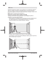
Checking the Height Accuracy of the Horizontal Line
For this check, you will need a free measuring distance of 5m on firm
ground between two walls (designated A andB).
– Mount the measuring tool close to wallA on a tripod, or place it on a firm,
level surface. Switch on the measuring tool. Select cross-line mode with
automatic levelling.
A
B
5 m
– Aim the laser at the closer wall A and allow the measuring tool to level in.
Mark the middle of the point at which the laser lines cross on the wall
(pointI).
Bosch Power Tools 1 609 92A 58R | (04.03.2020)

14 | English
A
B
180°
– Turn the measuring tool 180°, allow it to level in and mark the point
where the laser lines cross on the opposite wall B (point).
– Position the measuring tool –without rotating it– close to wallB, switch
it on and allow it to level in.
A
B
– Align the height of the measuring tool (using the tripod or by placing ob-
jects underneath as required) so that the point where the laser lines cross
exactly hits the previously marked point on wallB.
1 609 92A 58R | (04.03.2020) Bosch Power Tools

English | 15
d
180°
A
B
– Turn the measuring tool 180° without adjusting the height. Aim it at wallA
such that the vertical laser line runs through the already marked point.
Allow the measuring tool to level in and mark the point where the laser
lines cross on wallA (point).
– The discrepancy d between the two marked points and on wallA re-
veals the actual height deviation of the measuring tool.
The maximum permitted deviation on the measuring distance of
2×5m=10m is as follows:
10m×±0.5mm/m=±5mm. The discrepancy d between points and
must therefore amount to no more than 5mm.
Checking the Level Accuracy of the Horizontal Line
For this check, you will need a free area of 5×5m.
– Mount the measuring tool in the middle between wallsA and B on a tri-
pod, or place it on a firm, level surface. Select horizontal mode with auto-
matic levelling and allow the measuring tool to level in.
Bosch Power Tools 1 609 92A 58R | (04.03.2020)

16 | English
2,5 m
5,0 m
5,0 m
5,0 m
5,0 m
0 m
5,0 m
5,0 m
0 m
5,0 m
5,0 m
A
B
– At a distance of 2.5m from the measuring tool, mark the centre of the
laser line on both walls (point on wallA and point on wallB).
2,5 m
d
5,0 m
2,5 m
5,
0 m
A
B
– Set up the measuring tool at a 5m distance and rotated by 180° and al-
low it to level in.
– Align the height of the measuring tool (using the tripod or by placing ob-
jects underneath as required) so that the centre of the laser line exactly
hits the previously marked point on wallB.
1 609 92A 58R | (04.03.2020) Bosch Power Tools

English | 17
– Mark the centre of the laser line on wallA as point (vertically above or
below point).
– The discrepancy d between the two marked points and on wallA re-
veals the actual horizontal deviation of the measuring tool.
The maximum permitted deviation on the measuring distance of
2×5m=10m is as follows:
10m×±0.5mm/m=±5mm. The discrepancy d between points and
must therefore amount to no more than 5mm.
Checking the Levelling Accuracy of the Vertical Lines
For this check, you will need a door opening (on solid ground) which has at
least 2.5m of space either side of the door.
– Place the measuring tool 2.5m away from the door opening on a firm, flat
surface (not on a tripod). Select vertical mode with automatic levelling.
Aim the vertical laser line at the door opening and allow the measuring
tool to level in.
2,5 m
2,5 m
– Mark the centre of the vertical laser line on the floor of the door opening
(point), 5m away on the other side of the door opening (point) and on
the upper edge of the door opening (point).
Bosch Power Tools 1 609 92A 58R | (04.03.2020)

18 | English
2 m
d
– Rotate the measuring tool 180° and position it on the other side of the
door opening, directly behind point. Allow the measuring tool to level in
and align the vertical laser line in such a way that its centre passes
through points and exactly.
– Mark the centre of the laser line on the upper edge of the door opening as
point.
– The discrepancy d between the two marked points and reveals the
actual vertical deviation of the measuring tool.
– Measure the height of the door opening.
You can calculate the maximum permitted deviation as follows:
Doubled height of the door opening×0.5mm/m
Example: At a door opening height of 2m, the maximum deviation amounts
to
2×2m×±0.5mm/m=±2mm. The points and must therefore be no
further than 2mm from each other.
Working Advice
u Only the centre of the laser line must be used for marking. The width
of the laser line changes depending on the distance.
Working with the Tripod (Accessory)
A tripod offers a stable, height-adjustable support surface for measuring.
Place the measuring tool with the 1/4" tripod mount (12) on the thread of
1 609 92A 58R | (04.03.2020) Bosch Power Tools

English | 19
the tripod (14) or a conventional camera tripod. Tighten the measuring tool
using the locking screw of the tripod.
Roughly align the tripod before switching on the measuring tool.
Attaching with the holder
Using the holder(9), you can attach the measuring tool to various objects up
to 10 to 60 mm thick, e.g. to vertical or horizontal boards or pipes.
Loosen the fastening screw(8) of the holder, position the holder in the de-
sired location and retighten the fastening screw.
Place the measuring tool with the tripod mount(12) on the 1/4" screw(6)
of the holder and tighten it to secure it on the holder applying moderate
force. Do not tighten the measuring tool firmly as this could cause damage.
Roughly align the holder before switching on the measuring tool. To do this,
loosen the locking screw(7) of the holder and move the measuring tool into
a horizontal position at the desired height. Retighten the locking screw.
Laser Goggles (Accessory)
The laser goggles filter out ambient light. This makes the light of the laser ap-
pear brighter to the eye.
u Do not use the laser goggles as protective goggles. The laser goggles
make the laser beam easier to see; they do not protect you against laser
radiation.
u Do not use the laser goggles as sunglasses or while driving. The laser
goggles do not provide full UV protection and impair your ability to see
colours.
Maintenance and Service
Maintenance and Cleaning
Keep the measuring tool clean at all times.
Never immerse the measuring tool in water or other liquids.
Wipe off any dirt using a damp, soft cloth. Do not use any detergents or
solvents.
The areas around the outlet aperture of the laser in particular should be
cleaned on a regular basis. Make sure to check for lint when doing this.
Bosch Power Tools 1 609 92A 58R | (04.03.2020)

20 | English
After-Sales Service and Application Service
Our after-sales service responds to your questions concerning maintenance
and repair of your product as well as spare parts. You can find explosion
drawings and information on spare parts at: www.bosch-pt.com
The Bosch product use advice team will be happy to help you with any ques-
tions about our products and their accessories.
In all correspondence and spare parts orders, please always include the
10‑digit article number given on the nameplate of the product.
Cambodia
Robert Bosch (Cambodia) Co., Ltd
Unit 8BC, GT Tower, 08th Floor, Street 169,
Czechoslovakia Blvd, Sangkat Veal Vong
Khan 7 Makara, Phnom Penh
VAT TIN: 100 169 511
Tel.: +855 23 900 685
Tel.: +855 23 900 660
www.bosch.com.kh
People’s Republic of China
China Mainland
Bosch Power Tool (China) Co. Ltd.
Bosch Service Center
567, Bin Kang Road
Bin Kang District
Hangzhou, Zhejiang Province
China 310052
Tel.: (0571) 8887 5566 / 5588
Fax: (0571) 8887 6688 x 5566# / 5588#
E-Mail: [email protected]
www.bosch-pt.com.cn
HK and Macau Special Administrative Regions
Robert Bosch Co. Ltd.
21st Floor, 625 King’s Road
North Point, Hong Kong
Customer Service Hotline: +852 2101 0235
Fax: +852 2590 9762
E-Mail: [email protected]
www.bosch-pt.com.hk
1 609 92A 58R | (04.03.2020) Bosch Power Tools
La page charge ...
La page charge ...
La page charge ...
La page charge ...
La page charge ...
La page charge ...
La page charge ...
La page charge ...
La page charge ...
La page charge ...
La page charge ...
La page charge ...
La page charge ...
La page charge ...
La page charge ...
La page charge ...
La page charge ...
La page charge ...
La page charge ...
La page charge ...
La page charge ...
La page charge ...
La page charge ...
La page charge ...
La page charge ...
La page charge ...
La page charge ...
La page charge ...
La page charge ...
La page charge ...
La page charge ...
La page charge ...
La page charge ...
La page charge ...
La page charge ...
La page charge ...
La page charge ...
La page charge ...
La page charge ...
La page charge ...
La page charge ...
La page charge ...
La page charge ...
La page charge ...
La page charge ...
La page charge ...
La page charge ...
La page charge ...
La page charge ...
La page charge ...
La page charge ...
La page charge ...
La page charge ...
La page charge ...
La page charge ...
La page charge ...
La page charge ...
La page charge ...
La page charge ...
La page charge ...
La page charge ...
La page charge ...
La page charge ...
La page charge ...
La page charge ...
La page charge ...
La page charge ...
La page charge ...
La page charge ...
La page charge ...
La page charge ...
La page charge ...
La page charge ...
La page charge ...
La page charge ...
La page charge ...
La page charge ...
La page charge ...
La page charge ...
La page charge ...
La page charge ...
La page charge ...
La page charge ...
La page charge ...
La page charge ...
La page charge ...
La page charge ...
La page charge ...
La page charge ...
La page charge ...
La page charge ...
La page charge ...
La page charge ...
La page charge ...
La page charge ...
La page charge ...
La page charge ...
La page charge ...
La page charge ...
La page charge ...
La page charge ...
La page charge ...
La page charge ...
La page charge ...
La page charge ...
-
 1
1
-
 2
2
-
 3
3
-
 4
4
-
 5
5
-
 6
6
-
 7
7
-
 8
8
-
 9
9
-
 10
10
-
 11
11
-
 12
12
-
 13
13
-
 14
14
-
 15
15
-
 16
16
-
 17
17
-
 18
18
-
 19
19
-
 20
20
-
 21
21
-
 22
22
-
 23
23
-
 24
24
-
 25
25
-
 26
26
-
 27
27
-
 28
28
-
 29
29
-
 30
30
-
 31
31
-
 32
32
-
 33
33
-
 34
34
-
 35
35
-
 36
36
-
 37
37
-
 38
38
-
 39
39
-
 40
40
-
 41
41
-
 42
42
-
 43
43
-
 44
44
-
 45
45
-
 46
46
-
 47
47
-
 48
48
-
 49
49
-
 50
50
-
 51
51
-
 52
52
-
 53
53
-
 54
54
-
 55
55
-
 56
56
-
 57
57
-
 58
58
-
 59
59
-
 60
60
-
 61
61
-
 62
62
-
 63
63
-
 64
64
-
 65
65
-
 66
66
-
 67
67
-
 68
68
-
 69
69
-
 70
70
-
 71
71
-
 72
72
-
 73
73
-
 74
74
-
 75
75
-
 76
76
-
 77
77
-
 78
78
-
 79
79
-
 80
80
-
 81
81
-
 82
82
-
 83
83
-
 84
84
-
 85
85
-
 86
86
-
 87
87
-
 88
88
-
 89
89
-
 90
90
-
 91
91
-
 92
92
-
 93
93
-
 94
94
-
 95
95
-
 96
96
-
 97
97
-
 98
98
-
 99
99
-
 100
100
-
 101
101
-
 102
102
-
 103
103
-
 104
104
-
 105
105
-
 106
106
-
 107
107
-
 108
108
-
 109
109
-
 110
110
-
 111
111
-
 112
112
-
 113
113
-
 114
114
-
 115
115
-
 116
116
-
 117
117
-
 118
118
-
 119
119
-
 120
120
-
 121
121
-
 122
122
-
 123
123
-
 124
124
-
 125
125


Bosch GLL 2 Professional Original Instructions Manual
- Taper
- Original Instructions Manual
- Ce manuel convient également à
Documents connexes
-
Bosch GLL 5-50 X Mode d'emploi
-
Bosch GBL 620 Original Instructions Manual
-
Bosch GLL 2-80 P Professional Original Instructions Manual
-
-
-
Bosch PWS 750-115 Original Instructions Manual
-
-
Bosch PLR 40 C Le manuel du propriétaire
-
Bosch 0 603 663 001 Manuel utilisateur
-
Bosch GLL 2 Professional Le manuel du propriétaire