Spektrum AR8360T Manuel utilisateur
- Catégorie
- Jouets télécommandés
- Taper
- Manuel utilisateur

Spektrum AR8360T AS3X and SAFE
8 CH Receiver

EN
2
NOTICE
All instructions, warranties and other collateral documents are subject to
change at the sole discretion of Horizon Hobby, LLC. For up-to-date product
literature, visit horizonhobby.com or towerhobbies.com and click on the support
or resources tab for this product.
Meaning of Special Language
The following terms are used throughout the product literature to indicate
various levels of potential harm when operating this product:
WARNING: Procedures, which if not properly followed, create the probability
of property damage, collateral damage, and serious injury OR create a high
probability of supercial injury.
CAUTION: Procedures, which if not properly followed, create the probability
of physical property damage AND a possibility of serious injury.
NOTICE: Procedures, which if not properly followed, create a possibility of
physical property damage AND a little or no possibility of injury.
WARNING: Read the ENTIRE instruction manual to become familiar
with the features of the product before operating. Failure to operate
the product correctly can result in damage to the product, personal
property and cause serious injury.
This is a sophisticated hobby product. It must be operated with caution
and common sense and requires some basic mechanical ability. Failure to
operate this Product in a safe and responsible manner could result in injury
or damage to the product or other property. This product is not intended for
use by children without direct adult supervision. Do not attempt disassembly,
use with incompatible components or alter product in any way without the
approval of Horizon Hobby, LLC. This manual contains instructions for safety,
operation and maintenance. It is essential to read and follow all the instruc-
tions and warnings in the manual, prior to assembly, setup or use, in order to
operate correctly and avoid damage or serious injury.
Age Recommendation: Not for children under 14 years. This is not a toy.
WARNING AGAINST COUNTERFEIT PRODUCTS
Always purchase from a Horizon Hobby, LLC authorized dealer to ensure
authentic high-quality Spektrum product. Horizon Hobby, LLC disclaims
all support and warranty with regards, but not limited to, compatibility and
performance of counterfeit products or products claiming compatibility with
DSM or Spektrum technology.
NOTICE: This product is only intended for use with unmanned, hobby-grade,
remote-controlled vehicles and aircraft. Horizon Hobby disclaims all liability outside
of the intended purpose and will not provide warranty service related thereto.
WARRANTY REGISTRATION
Visit www.spektrumrc.com/registration today to register your product.

EN
3
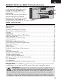
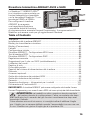
AR8360T AS3X and SAFE Telemetry Receiver
The Spektrum™ AR8360T Receiver
is full range with telemetry, and is
compatible with all Spektrum™
DSM2® and DSMX® technology
transmitters.
Perform the setup for the AR8360T
receiver through a compatible
Spektrum Transmitter with Forward
Programming. The Spektrum PC
Programmer can be used for rmware updates.
IMPORTANT: The AR8360T receiver only uses forward programming for the
conguration, do not use the AS3X menu in the main transmitter menu.
Table of Contents
WARNING: If equipped, the propeller should not be installed on the
motor during the setup procedure. Only install the propeller once the
throttle has been conrmed to operate correctly and the failsafe has been set.
As an additional safety feature, we recommend the throttle cut is enabled.
Throttle cut should be engaged any time the aircraft is powered on and not
in operation. The motor will not rotate when throttle cut is in the ON position.
Smart Throttle .............................................................................................. 4
Specications ..............................................................................................4
Telemetry ....................................................................................................5
Installing the AR8360T Receiver ...................................................................5
Transmitter and Receiver Binding ..................................................................6
Failsafe ......................................................................................................7
Initial Setup .................................................................................................7
AR8360T Receiver- Basic AS3X Setup ..........................................................8
AS3X Reaction Test ......................................................................................9
AR8360T Receiver- SAFE Setup..................................................................10
Advanced Tuning ........................................................................................11
SAFE (Self Leveling) Flying Tips ...................................................................14
Other Settings (Forward Programming) ........................................................ 14
Channel Limitations ....................................................................................15
Flight Log ..................................................................................................16
Range Testing ............................................................................................17
Receiver Power System Requirements ......................................................... 18
Glossary ....................................................................................................18
Optional Accessories ..................................................................................19
Troubleshooting Guide AS3X .......................................................................20
Troubleshooting Guide ................................................................................21
1-YEAR LIMITED WARRANTY ......................................................................23
Warranty and Service Contact Information ...................................................25
FCC Information ......................................................................................... 25
IC Information ............................................................................................27
Compliance Information for the European Union ...........................................27

EN
4
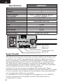
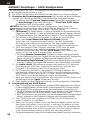
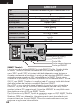
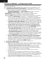
Smart Throttle
With Smart Technology the normal servo connector delivers the throttle signal
to the ESC, plus the ESC can send telemetry data like voltage and current
back to the receiver. The AR8360T receiver throttle port (Channel 1 port only)
will automatically detect when a Smart compatible ESC is connected. ESCs
with Smart and IC series connectors can also pass along battery data from
compatible Spektrum Smart batteries. Spektrum Avian™ ESCs are compatible
with the AR8360T receiver for Smart Technology features.
For Smart to function you must have a Smart ESC paired with a Smart
telemetry receiver, and a Spektrum DSMX transmitter with telemetry. An update
for your transmitter may be required for Smart features. See www.spektrumrc.
com to register and update your transmitter.
If a standard ESC or servo is plugged into the throttle port on the AR8360T
receiver, the throttle port will operate normally (PWM signal) like any
conventional RC system.
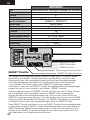
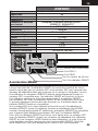
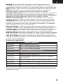
XBUS Port
SRXL2 Port
Bind Button
Smart Port
Voltage Sensor Port
AR8360T
Type DSM2/DSMX 6 CH AS3X Telemetry Receiver
Application Air
Channels 8
Receivers 1
Remote Receiver
(not included)
SRXL2™ Remote Receiver Optional
[SPM9747, SPM4651T]
Modulation DSM2/DSMX
Telemetry Integrated
Bind Method Bind Button, Bind Plug
Failsafe Yes
Band 2.4GHz
Dimensions (LxWxH) 49 x 30 x 15mm
Weight 16g
Input Voltage 3.5–9V
Resolution 2048
Antenna Length 155mm and 186mm
Specifications

EN
5
Installing the AR8360T Receiver
1. Mount the receiver using double-sided servo tape. The receiver may be
mounted upright, upside down or on its side, but it should be square with
the fuselage in its mounting position. The receiver cannot be mounted at
an odd angle.
TIP: For SAFE setups, install the receiver as close to the center of gravity of
the aircraft as practical.
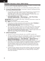
2. Connect the servos to their respective ports on the receiver using the chart
below.
CAUTION: Incorrect installation of the receiver could cause a
crash. Always perform a control surface check and AS3X control
surface response test before ying a new setup, or after any setup changes.
DEFAULT CHANNEL ASSIGNMENTS
AR8360T Port Assignments
Bind/Prog/SRXL2= Bind, Aux Device Support, Program
1 Throttle (Smart Throttle)
2 Aileron
3 Elevator
4 Rudder
5 Gear
6 Aux 1
7 Aux 2
8 Aux 3
Telemetry
The AR8360T features full range telemetry and will provide receiver battery
voltage, ight log data, vertical speed, and altitude data without any additional
sensors. Additional telemetry devices such as voltage sensors can be
connected to the volt port, and XBus telemetry sensors can be connected
through the XBus connector. Every XBus telemetry device has two XBus ports,
and XBus telemetry sensors can be connected in a daisy chain in any order.
The AR8360T is not compatible with the Spektrum Temperature Sensor (SPMA9571)
See www.spektrumrc.com for more information about telemetry accessories
IMPORTANT:
When using Y-harness or servo extensions with Spektrum
equipment, do not use reversing harnesses. Using reversing Y-harnesses or
servo extensions may cause servos to operate erratically or not function at all.

EN
6
Programming the AR8360T receiver requires a Spektrum™ DSM2®/DSMX®
compatible transmitter with Forward Programming.
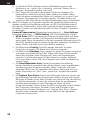
Transmitter and Receiver Binding
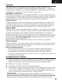
Binding
The AR8360T receiver must be bound to your transmitter before it will operate.
Binding is the process of teaching the receiver the specic code of the transmitter
so it will only connect to that specic transmitter.
1. Connect the optional SRXL2 remote receiver (SPM9747 or SPM4651T) if
desired and any telemetry sensors to the main receiver.
2. Push and hold the bind button on the receiver while turning the receiver on.
Release the bind button once
the orange LED starts
to ash continuously,
indicating the receiver
is in bind mode.
TIP: It is still possible to
use a bind plug in the
bind port if desired. This can
come in handy if the receiver needs
to be mounted in a location that is difcult
to access, in which case a servo extension may
be used for binding. If using a bind plug, remove after
binding to prevent the system from entering bind mode
the next time the power is turned on.
3. Put your transmitter in bind mode.
4. The bind process is complete when the orange LED on the receiver is solid.
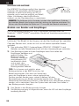
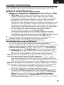
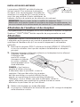
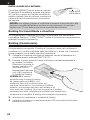
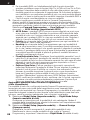
ANTENNA INSTALLATION
The AR8360T receiver has coaxial style
antennas. We recommend installing the
antennas oriented 90º from each other and as
far as possible from metal, batteries, carbon
ber or fuel tanks to maximize signal reception
performance.
NOTICE: Do not cut, kink, or modify the antennas. Damage to the coaxial
portion of an antenna will reduce the performance of the antenna.
Shortening or cutting off the 31mm tip will reduce the range.
Active portion
of antenna

EN
7
Failsafe
In the unlikely event the radio link is lost during use, the receiver will enable
the selected failsafe mode. Smart Safe + Hold Last is the default failsafe mode
on the AR8360T. Preset Failsafe and SAFE Failsafe modes are only available
through Forward Programming.
SmartSafe + Hold Last
If loss of signal occurs, SmartSafe™ technology moves the throttle channel to
the failsafe position (low throttle) set during binding. All other channels will hold
their last position. When the receiver detects the signal from the transmitter,
normal aircraft operation resumes.
Preset Failsafe
With preset failsafe, you can set the specic control surface positions you
want to use if the signal is lost. When the receiver detects the signal from the
transmitter, normal aircraft operation resumes.
Preset failsafe mode is only available through Forward Programming.
SAFE Failsafe
SAFE Failsafe mode will work to automatically level your aircraft if the signal
is lost. In the forward programming menu you can select the bank and pitch
angles the aircraft will attempt to maintain during failsafe. We recommend
setting bank and pitch angles so the aircraft ies a gentle gliding turn,
preventing a yaway. You must complete First Time SAFE Setup before this
option is available.
SAFE Failsafe mode is only available through Forward Programming.
Testing Failsafe
Secure the aircraft on the ground and remove the propeller. Test Failsafe
settings by turning the transmitter RF output off and noting how the receiver
drives the control surfaces.
Receiver Power Only
• The servo ports will not have a control signal if the receiver is turned on
when no transmitter signal is present.
• All channels have no output until the receiver has linked to the transmitter.
Initial Setup
1. Verify your transmitter is updated to the latest Spektrum AirWare™ software
to take advantage of Forward Programming. See your transmitter manual
for updating instructions.
2. Install
the receiver in your airplane.
3. Bind the receiver to your transmitter.
4. Complete the airplane setup on your transmitter including wing type, tail type, channel
assignments, mixing, sub trim and travel the same as you would for any other aircraft
without AS3X. Verify the center of gravity is correct and test y your aircraft.
IMPORTANT: Do not use open mixes for ight control surfaces when setting
up a model with the AR8360T for AS3X and SAFE. Only use wing and tail type
options to congure ight controls, refer to your transmitter manual for more
information about wing and tail type features.

EN
8
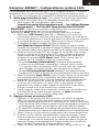
AR8360T Receiver- Basic AS3X Setup
To use AS3X technology with the Spektrum AR8360T Receiver, the receiver needs
to be set up with a compatible Spektrum transmitter.
1. Verify the basic setup and trim is accurate before attempting AS3X setup.
2. Forward Programming Setup: The receiver is directly congured through
the Forward Programming menu.
1. Low throttle is required to enter Forward Programming, we recommend
enabling throttle cut and verify it prevents motor operation. The
transmitter will not allow you to enter the Forward Programming menu
unless throttle is low or throttle cut is activated.
2. In your transmitter’s menu, select:
Forward Programming -> Gyro Settings -> First Time Setup
The transmitter will prompt you for all setup steps.
IMPORTANT: Before proceeding with setup, read every information screen that
appears on your transmitter
Select NEXT at the bottom of each page to continue.
3. Follow the on-screen prompts to set the orientation. Select
Continue
to
complete the two-step auto detection process, or select
Set Orientation Manually
. Verify the orientation is correct.
4. You can a
ssign any open channel to a switch (trimmer, knob, etc) for gain,
and assign that channel for gain. You can assign a switch to a channel
from
the Forward Programming menu so you don’t have to exit the
menu.
We recommend using a trim
mer, knob, or slider for gain, which will
enable you to change the gain value on the y.
When the setup screens are complete select Apply.
3. AS3X Tuning Basics:
1. Perform a control surface direction test, and AS3X reaction test.
2. Test y the airplane to verify the conguration. In-ight trim changes do
not require any further updates. If the airplane needs sub-trim, travel or
other setup changes in the transmitter programming, select
Forward Programming -> Gyro Settings -> System Settings ->
Relearn Servo Settings after making the needed changes.
3. Oscillation occurs because the system is overshooting the correction, and
will usually occur at higher speeds. If the airplane oscillates, immediately
reduce speed and lower the gain value. Take note of which axis the
aircraft oscillates around; you can increase or decrease the base gain
values of each axis separately within the Forward Programming menu
after landing.
4. Increase the gain values until you nd oscillation, and then reduce the
gain to the highest setting that will not cause oscillation at any speed.
This value will help the airplane track accurately and y smoothly in
wind and turbulence.

EN
9
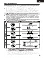
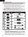
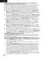
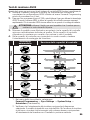
AS3X Reaction Test
This test ensures that the AS3X control system is functioning properly.
1. Assemble the aircraft, bind your transmitter to the receiver, and complete the
AS3X First Time Setup in the Forward Programming menu before performing
this test.
2. Raise the throttle above 25% to activate AS3X, then lower the throttle. Once
the AS3X system is active, control surfaces move in response to aircraft
movement. AS3X remains active until the battery is disconnected.
CAUTION: Activate throttle cut to prevent motor operation during
this test.
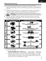
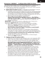
3. Move the aircraft as shown and ensure the control surfaces move in the
direction indicated in the graphic. If the control surfaces do not respond as
shown, do not y the aircraft.
Aircraft Movement Control Surface Reaction
RudderElevator
Aileron
4. If the control surfaces do not respond as shown, review the receiver
mounting orientation.
1. In your transmitter’s menu select
Forward Programming -> Gyro Settings -> System Setup -> Orientation
2. Verify the receiver orientation matches the selected diagram. The image
of the airplane is from the top. If your access to the receiver is from the
bottom, remember the images on the screen need to match the way the
receiver sits in the model when it is upright.

EN
10
AR8360T Receiver- SAFE Setup
Setting up SAFE Technology on the AR8360T Receiver takes place in Forward
Programming.
1. Complete the AS3X setup and verify operation in ight.
2. Forward Programming Setup: To add SAFE ight stabilization the Flight
Modes on the receiver need to be congured.
1. In your transmitter’s menu select
Forward Programming
->
Gyro Settings
->
First Time SAFE Setup
IMPORTANT: Before proceeding with setup, read every information screen that
will appear on your transmitter screen.
Select NEXT at the bottom of each page to continue.
2. Select FM Channel-> Select the channel and switch you want to use
for Flight Mode selection. You can select any channel that is not a control
surface, throttle or gain. Select Continue.
3. Position the model in a level ight attitude, then select
Level Model and Capture Attitude to teach the receiver the baseline
setting. For taildragger aircraft be sure to raise the tail so the fuselage is level.
4. Assign SAFE to the desired ight modes. You can enable or disable SAFE
for each ight mode. Take into account your ight mode switch position,
and set the SAFE Mode as desired for the rst switch position.
• Envelope (Intermediate) mode does not use self leveling. The aircraft
will y like a normal AS3X setup, but it will be bank and pitch angle limited.
• Self Leveling/Angle Demand will make the airplane return to level
ight when the control stick is centered.
5. Set the Angle Limits as desired for the rst switch position. These
values determine how far the aircraft will be allowed to pitch or bank.
6. Move the Flight Mode switch to the other positions, a setup screen for
SAFE Mode and Angle Limits will appear for each mode. Set the SAFE
Mode and Angle Limits as desired for every mode.
7. After all the Flight Modes are congured as desired for SAFE Modes and Angle
Limits, press Apply.
8. Test y the airplane to verify the conguration.
3. Tuning SAFE Basics:
1. Perform a control surface direction test, and AS3X reaction test. You can verify
which modes have SAFE enabled by performing the AS3X test, starting at the
level ight attitude.
• AS3X reaction will move the control surfaces in response to rotational
movement, and then return to center when the rotation stops.
• SAFE (Self Leveling) will
cause the control surfaces to stay deected as long
as the aircraft is banked or pitched.
2. Test y the airplane to verify the conguration in every ight mode.
3. If the airplane oscillates, immediately slow it down and reduce gain. Take note
of which ight mode you are in and which axis the aircraft oscillates around. You
can increase or decrease the base gain values of each axis separately for each
ight mode within the Forward Programming menu after landing.
4. Tune gain values for each axis within each ight mode.

EN
11
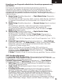
Advanced Tuning
Basic gain tuning can be as simple as using a slider, but to ne tune the AS3X
system there are many setup and tuning options.
AS3X Gain tuning options
1. In your transmitter’s menu select
Forward Programming -> Gyro Settings -> AS3X Settings
• AS3X Gains can be changed for each axis, you can increase the gain values
for roll, pitch and yaw separately to maximize the performance without
oscillation. We recommend making small changes on one axis at a time.
• Priority tells the receiver how much to reduce gain when you move the
control stick away from center. If the Priority is set high (200) the receiver
will lower gain to zero with any movement on the control stick. Low
priority values will dampen more throughout the control input range. The
default value of 160 provides a well balanced feel for most pilots.
• If your aircraft is over or under sensitive to the range of gain available,
adjust the Gain Sensitivity. Agile aircraft with extreme control surface
deections or high speed aircraft should use 1X. Moderate sport airplanes
should use 2X. Slow and inherently stable aircraft with mild performance
should use 4X.
2. Test y your airplane to verify the conguration, land, and make adjustments
as necessary.
Flight Mode tuning options within Forward Programming
(in the receiver)
1. Flight Modes in Forward Programming are set up in the receiver and are
separate from Flight Modes set up outside of Forward Programming. You can set
base gain values, and enable or inhibit AS3X and SAFE for each Flight Mode.
Select Forward Programming -> Gyro Settings -> F-Mode Setup
1. Select FM Channel, assign a channel and switch to use for Flight Modes.
Select any channel that is not a control surface, throttle or gain.
TIP: If you have completed the First Time SAFE Setup, your Flight Modes will
already be assigned to a switch.
2. Each Flight Mode within Forward Programming can have AS3X and SAFE
enabled or disabled. For all ight modes with SAFE enabled, AS3X should
be enabled as well. Take into account your ight mode switch position,
then set the AS3X and SAFE Modes as desired for that switch position.
TIP: If you have not completed the First Time SAFE Setup, you will not see any
SAFE related options on the F-Mode Setup Screens.
3. SAFE Flight Modes have an AS3X gain and a SAFE gain for pitch and roll axis.
Both of these values are used for SAFE and may be tuned independently.
4. Enable the Panic function if you want to be able to trigger Panic (bailout)
from that ight mode. This setting only denes if Panic is accessible from
the selected Flight Mode. Complete Panic Mode Setup under
Forward Programming -> System Setup -> SAFE/Panic Mode Setup
5. For Modes with SAFE self leveling/angle demand, you can choose to
enable High Thr to Pitch and/or Low Thr to Pitch or not.
6. Move the Flight Mode switch to the other positions; a setup screen will
appear for each mode. If Panic is not enabled on a selected mode, you
will not be able to trigger Panic when you are in that Flight Mode. Set the
SAFE Mode and Angle Limits as desired for every mode.

EN
12
2. When you add Flight Modes within Forward Programming, additional tuning
options are added in the AS3X Setting menu. Be sure to change through all
the ight modes with your assigned switch and verify values for each feature
for every ight mode.
Select Forward Programming -> Gyro Settings -> AS3X Settings
• AS3X Gains can be adjusted for each axis and each mode. Change the
ight mode switch position when this option is selected and a separate
screen will appear for AS3X gains on each ight mode. Adjust the values
in each mode and each axis as needed.
• Priority screens will also appear for each ight mode, adjust the values
as desired.
• Heading screens will appear for each ight mode and are defaulted to
zero. You can increase this value to make the aircraft hold its attitude
when control input is neutral. Heading gain on the yaw axis is generally
not recommended because it will require the pilot to steer the aircraft
through any heading changes.
• Fixed/Adjustable Gain will let you use xed values or adjust the gain
from the assigned Gain channel. Each Flight Mode has a separate
screen with a separate set of values so each axis can be set to Fixed or
Adjustable in each Flight Mode.
• Capture Gyro Gains lets you easily set your base gain setting. If you are
using a slider, knob or trimmer to adjust gain when test ying, you can set
the value you arrive at as the base gain setting in the ight modes using
this function. Select this option from the AS3X Settings menu, verify ight
mode, verify the slider, knob or trimmer is in the desired position, and
select Capture Gyro Gains to set the values for the chosen Flight Mode.
Adding Flight Modes outside of Forward Programming
(in the transmitter)
Flight Modes outside of forward programming are set up in the main transmitter
menu and are separate from Flight Modes set up within forward programming.
Flight Modes in the transmitter tie together transmitter-based features like dual
rates and expo, selected channels and positions, trim, and voice/sound features.
1. Select Model Setup -> Flight Mode Setup
Assign a switch for the ight mode selection. See your transmitter manual for
more information about setting up Flight Modes on your transmitter.
2. Select Model Setup -> Channel Assign
Link the functions by assigning the Flight Mode channel. Select the same
Flight Mode channel you picked within forward programming, set the switch
to Flight Mode.
3. Select Model Setup -> Digital Switch Setup
Match the Flight Mode functions. Select Flight Mode in the switch selection,
a set of values appears for each ight mode.
Set Flight Mode 1 to 100%, Flight Mode 2 to 0%, and Flight Mode 3 to -100%.
4. Select Forward Programming -> Gyro Settings -> F-Mode Setup
Verify the ight modes change as expected when moving the Flight Mode
Switch.
5. (Only applies to transmitter with trimmer switches, DX9 and higher)
If you wish to be able to run a trimmer for gain independent for each ight
mode, Select Model Setup -> Trim Setup
Select F-Mode for the trimmer that is assigned to gain.

EN
13
SAFE Setting menu.
The
First Time SAFE Setup
should be sufcient to y your airplane, but to ne
tune the SAFE system there are many setup and tuning options.
Select Forward Programming -> Gyro Settings -> SAFE Settings ->
• SAFE Gains can be ne tuned for each axis within each Flight Mode.
• Angle Limits can be changed for each ight mode
• Fixed/ Adjustable Gain operates the same as this feature in AS3X, but
applies to SAFE gain. You can assign a separate SAFE gain channel for roll
and pitch if you have enough free channels. Use a different gain channel for
SAFE gain than what you have assigned for AS3X. It is possible to have up
to ve different channels assigned for ne tuning gain. AS3X roll, pitch and
yaw, and SAFE roll and pitch. If you are limited by channels, make your gain
changes within Forward Programming.
• Capture Gyro Gains operates the same as this feature in AS3X, but applies
to SAFE operation
(AS3X) System Setup
Select Forward Programming -> Gyro Settings -> System Settings ->
• Relearn Servo Settings can be accessed if any changes are made to the
model conguration outside of Forward Programming. If any changes are
made to servo reversing, travel, sub-trim, wing type or tail type, you can
execute this function instead of restoring factory defaults and redoing the
entire setup.
• Orientation can be changed from this menu if the receiver mounting is changed.
• Gain Channel enables you to change the channel you are using to manage gain.
• SAFE/Panic Mode Setup
1. Panic
Select a channel to trigger Panic mode. Chose any channel that is not
used for a control surface, throttle, ight modes, or gain. We recommend
assigning the momentary I button for Panic.
Delay will cause a two second delay when exiting panic mode
Panic Flight Mode selects a Flight Mode to pull the gain values from for
Panic operation; select a Flight Mode that is setup with SAFE
Roll and Pitch values on this page represent angle limits while in Panic mode.
2. Throttle To Pitch
Low Thr to Pitch Threshold determines the trigger point below which
the airplane will descend nose down at the chosen angle.
High Thr to Pitch Threshold determines the trigger point above which
the airplane climbs at the chosen angle.
3. Attitude Trim allows you to redo the Capture Level Flight Attitude, and/or
manually ne tune the values based on ight testing.
4. SAFE Failsafe Flight Mode allows you to select a ight mode (with
SAFE congured) to act as a failsafe mode. Making this selection enables
SAFE Failsafe.
5. Failsafe Angles determine the attitude the aircraft will maintain in the
event of a failsafe. Set pitch and bank angles to hold the aircraft in a
gentle gliding turn, preventing a yaway.
• Utilities -> Copy Flight Mode Settings
Select a Source and Target Flight Mode to transfer all Flight Mode settings
from one Flight Mode to another. All settings in the Target Flight Mode will be
overwritten.

EN
14
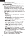
Other Settings (Forward Programming)
System Setup
Select Forward Programming -> Other Settings ->
• Select Failsafe -> Select each channel and assign it to Preset or Hold Last.
When you select a different channel for Output, a new group of settings appears.
Capture Failsafe Positions ->
Hold the control sticks in the desired failsafe positions and select Apply.
Channel selections must be individually set in Forward Programming to apply
the preset positions or each channel will default to Hold Last. The value
captured will be reected in the position shown for each channel.
• Initiate Receiver Bind Mode
Gives you the option of putting the receiver into Bind Mode from this menu.
• Factory Reset
Select this option to put the receiver back to factory defaults.
All settings will be wiped with this selection.
• Restore From Backup
Select this option to re-instate the model le saved into backup.
• Save to Backup
The AR8360T can store a second model setup le for backup. Use this option
if you want to store the settings you have while you test setup changes.
SAFE (Self Leveling) Flying Tips
When ying in SAFE Self Leveling/Angle Demand mode, the aircraft will return
to level ight any time the aileron and elevator controls are at neutral. Applying
aileron or elevator control will cause the airplane to bank, climb or dive. The
amount the stick is moved will determine the attitude the airplane ies. Holding
full control will push the aircraft to the pre-determined bank and roll limits, but
it will not go past those angles.
When ying with Self Leveling/Angle Demand, it is normal to hold the control
stick deected with moderate to full aileron input when ying through a turn. To
y smoothly with Self Leveling/Angle Demand, avoid making frequent control
changes and don’t attempt to correct for minor deviations. Holding deliberate
control inputs will command the aircraft to y at a specic angle, and the model
will make all corrections to maintain that ight attitude.
When ying with Self Leveling/Angle Demand, you have the option to enable
throttle to pitch angle demand. Throttle to pitch will make throttle dictate climb
angle. Full throttle will cause the aircraft to pitch up and climb slightly. Mid
throttle will keep the airplane ying level. Low throttle will cause the airplane to
descend slightly nose-down.
Return the elevator and aileron controls to neutral before switching from Self
Leveling/Angle Demand mode to AS3X mode. If you do not neutralize controls when
switching into AS3X mode, the control inputs used for Self Leveling/Angle Demand
mode will be excessive for AS3X mode and the aircraft will react immediately.

EN
15
Channel Limitations
The AR8360T can use up to seven extra channels for AS3X and SAFE functions;
one for Flight Mode selection, one for Panic Mode, and up to ve for Gain. You
may use any channel up to 20 that is not a control surface or throttle for these
functions, and you do not need to use channels 5 and 6, keeping those channels
and ports on the receiver open for normal servo operation. However, you may run
into channel limitations depending on the number of channels on your transmitter
and the number of channels you are using on the receiver.
TIP: If you are experiencing limitations because of channel count, here are a
few options;
• You can operate the AR8360T without a channel assigned to Flight Mode, but
you will only have access to AS3X options, not SAFE.
• You can set up one self-leveling mode to serve as Panic Mode so you don’t
need to dedicate a separate channel for Panic Mode.
• You can operate the AR8360T without a gain channel assigned, and just use
xed gain values throughout the conguration. To do this, rst assign ight
mode to a channel, then change all gain values to xed for ight mode 1, then
you can unassign the ight mode channel and it will remain in xed.
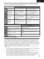
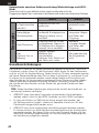
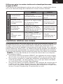
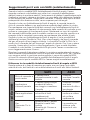
Differences between Self Leveling/Angle Demand and AS3X modes
This section is generally accurate but does not take into account ight speed,
battery charge status, and other limiting factors.
SAFE Beginner SAFE Intermediate
Control Input
Control stick
is neutralized Aircraft will self level Aircraft will continue to y
at its present attitude
Holding a
small amount
of control
Aircraft will bank or
pitch to a moderate
angle and maintain the
attitude
Aircraft will continue to
pitch or roll slowly, and
stop at the predetermined
bank angle limits
Holding full
control
Aircraft will bank or pitch
to the predetermined
limits and maintain the
attitude
Aircraft will continue to roll
or pitch rapidly, and stop
at the predetermined bank
angle limits
Throttle
(Optional: Thr
to Pitch)
Full throttle: Climb
Mid throttle: Level ight
Low throttle: Descend
nose-down
Throttle will not affect ight
response
AS3X
Control Input
Control stick is neutralized Aircraft will continue to y at its
present attitude
Holding a small amount of
control
Aircraft will continue to pitch or roll
slowly
Holding full control Aircraft will continue to roll or pitch
rapidly
Throttle
(Optional: Thr to Pitch)
Throttle will not affect ight response

EN
16
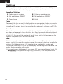
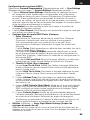
Flight Log
Flight Log data can help you optimize the control link for your aircraft. Flight
Log data is displayed on telemetry capable Spektrum transmitters.
Using the Flight Log
A - Fades on main receiver B - Fades on remote receiver
L - Not available on AR8360T R - Not available on AR8360T
F - Frame losses H - Holds
Fades
Represents the loss of one bit of information on one receiver. Fades are used to
evaluate the performance of each individual receiver. If a fade value is showing
higher than the others, inspect or reposition the antenna to optimize the RF link.
Frame Loss
A frame loss occurs when one complete data packet is missed. A single frame
loss does not represent a loss of control, but frame losses should be monitored.
In the air it's normal to experience as many as 100 frame losses per minute
of ight. On the ground the number of frame losses will be higher because the
signal is hampered by the dirt and moisture.
Hold
A hold occurs when 45 consecutive frame losses occur. This takes about one
second, and in this event the receiver moves the channel outputs to the failsafe
settings. If a hold ever occurs, it’s important to re-evaluate the system and
check every component. If your system displays a hold, diagnose the cause and
resolve the issue before ying again.
It is normal to see a hold logged if you power OFF your transmitter and back ON.
IMPORTANT: The Spektrum Flight Log (SPM9540) is not compatible with
the AR8360T receiver.

EN
17
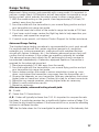
Range Testing
Before each ying session, and especially with a new model, it’s important to
perform a range check. All Spektrum aircraft transmitters incorporate a range
testing system, which reduces the output power to allow a range check.
1. With the model resting on the ground, stand approximately 100 feet (30
meters) away from the model.
2. Face the model with the transmitter in your normal ying position and put
your transmitter into range test mode.
3. You should have total control of the model in range test mode at 100 feet.
4. If you have control issues, review the ight log data to help reposition your
antenna(s), and repeat the range test.
5. If control issues persist, call Horizon Product Support for further assistance.
Advanced Range Testing
The standard range testing procedure is recommended for most sport aircraft.
For sophisticated aircraft that contain signicant amounts of conductive
materials (e.g. turbine powered jets, scale aircraft with metalized nishes,
aircraft with carbon fuselages, etc.), the following advanced range check will
conrm that all receivers in the system are operating optimally as installed.
This advanced range check allows the RF performance of each receiver to
be evaluated independently. A telemetry-equipped Spektrum Transmitter is
required for the advanced range test.
1. Stand approximately 100 feet away from the model.
2. Face the model with the transmitter in your normal ying position and put
your transmitter into range test mode.
3. Have a helper position the model in various orientations (nose up, nose
down, nose toward the transmitter, nose away from the transmitter, etc.).
4. Observe the telemetry on your transmitter. Note any orientations that cause
higher fades or frame loss values. Perform this step for at least one minute.
5. Reposition any remote receivers showing higher fades as necessary.
6. Retest to verify satisfactory results.
7. Repeat as necessary.
After one minute, advanced testing should yield:
H - 0 holds
F - Fewer than 10 frame losses
A, B - Fades will typically be fewer than 100. It’s important to compare the rela-
tive fades. If a particular receiver has a signicantly higher number of fades (2 to
3X) then the test should be redone. If the same results occur, move the offending
receiver to a different location.
TIP: Use the fade values for A to investigate the performance of the telemetry link.

EN
18
Glossary
AS3X- Stabilization technology that dampens wind and turbulence. Designed to
support advanced iers, AS3X does not include self-leveling technology.
SAFE Envelope- (Intermediate Mode) Stabilization technology that uses AS3X
to deliver normal ight performance, but with limited bank and pitch angles to
prevent the airplane from getting into extreme attitudes.
SAFE Self Level/Angle Demand- Stabilization technology that will make the
airplane return to level ight when the control stick is centered.
Panic Mode- Sometimes called a bailout mode, Panic is a SAFE stabilization
mode that can return an airplane to level ight from any attitude. It is usually
assigned to a momentary button.
Flight Modes in Receiver- Determine what stabilization modes the aircraft
operates in. All the associated stabilization features to tune the ight stabilization
can be adjusted per Flight Mode in the receiver (Base Gain, Priority, Heading, etc).
Flight Modes in Transmitter- Manage rates, expo, voice/sound output, and
other transmitter based congurations.
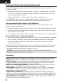
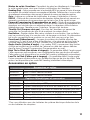
Receiver Power System Requirements
Some of the power system components that affect the power supply to the
receiver include:
• Receiver battery pack (number of cells, capacity, cell type, state of charge).
• The ESC’s capability to deliver adequate voltage to the receiver when the
servos demand high current
• The switch harness, battery leads, servo leads, regulators etc.
The AR8360T has a minimum operational voltage of 3.5 volts; it is highly
recommended the power system be tested per the guidelines below.
Recommended Power System Test Guidelines
We recommend performing the following tests on any new setup to verify
power system performance:
1. View the receiver voltage during this test on your transmitter’s telemetry screen
2. Load the control surfaces (apply pressure with your hand) while monitoring
the voltage at the receiver.
3. The voltage should remain above 4.8 volts even when all servos are loaded.
How QuickConnect™ Technology Works
• When the receiver voltage drops below 3.5 volts, the system ceases to operate.
• When power is restored, the receiver immediately attempts to reconnect.
• If the transmitter was left on, the system reconnects typically in about
4/100 of a second.
QuickConnect is designed to allow you to y safely through most short duration
power interruptions, however, the root cause of these interruptions must be
corrected before the next ight to prevent a crash.
NOTICE: If a brownout occurs in ight it is vital that the cause of the
brownout be determined and corrected.

EN
19
Optional Accessories
Optional Accessories
SPMA3065 USB Programming Cable
SPM9747 SRXL2 DSMX Remote Receiver
SPM4651T SRXL2 DSMX Remote Receiver
Telemetry Sensors and Accessories
SPMA9574 Aircraft Telemetry Airspeed Indicator
SPMA9587 Aircraft Telemetry GPS Sensor
SPMA9556 Air Telemetry Flight Pack Voltage Sensor: EC3/IC3
SPMA9604 Aircraft Telemetry Receiver Battery Energy Sensor
SPMA9605* Aircraft Telemetry Flight Pack Batt Energy Sensor*
SPMA9551 12" Aircraft Telemetry Extension
SPMA9552 24" Aircraft Telemetry Extension
*For use with electric power system batteries that are separate from the
receiver battery(s).
Heading- An optional feature of AS3X, heading will make the airplane try to hold
its attitude when the control is relaxed. This is not a self-leveling feature, it only
makes the aircraft track accurately.
Gain- Tells the stabilization system the level of damping it should provide.
SRXL2- A Bi-Directional data communication protocol that enables digital devices
to communicate over a single signal wire.
Forward Programming- Programming directly on the receiver from the
transmitter. The receiver has all screens, menus and settings in its internal
memory. The receiver is using the telemetry link to the transmitter for the
interface, the screen and buttons.
Throttle Cut- Disables throttle function
Oscillation- Sometimes called a wag, this is a back and forth movement similar
to a vibration that may appear like a wobble. It may occur around any axis, roll,
pitch or yaw. It is most likely to occur on one axis, not all three.
Overshoot- When the stability system makes corrections it is a balancing act,
if the response is too strong the system will go past where it should stop, this is
called an overshoot.
Angle Limits- Only available in SAFE modes, these values dene the limits for
the bank and pitch angles.
High Thr to Pitch- This setting denes the angle the airplane will climb at when
the throttle is raised above half. This is only available in Self Leveling modes.
Low Thr to Pitch- This setting denes the angle the airplane will descend at when
the throttle is lowered below half. This is only available in Self Leveling modes.
Brownout- If the receiver power supply drops below 3.5volts, the receiver will
not have sufcient power for operation and the resulting loss of control is call a
brownout. A brownout results from an inadequate power supply to the receiver, it
is a failure outside of the receiver.

EN
20
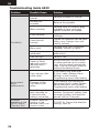
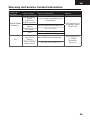
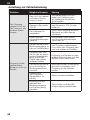
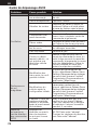
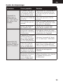
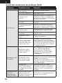
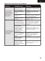
Troubleshooting Guide AS3X
Problem Possible Cause Solution
Oscillation
Damaged propeller or
spinner Replace propeller or spinner
Imbalanced
propeller Balance the propeller
Motor vibration Replace parts or correctly align
propeller or other parts and
tighten fasteners as needed
Loose receiver Align and secure receiver in
fuselage
Loose aircraft
controls
Tighten or otherwise secure parts
(servo, arm, linkage, horn and
control surface)
Worn parts Replace worn parts (especially
propeller, spinner, or servo)
Irregular servo
movement Replace servo and/or servo
extension(s)
Gain too high Reduce Gain
Travel or Rates
reduced causing
reduced servo
resolution
Move pushrod in on servo horn,
or move pushrod out on control
horn, and increase travel and/or
rates. Use the full servo travel to
achieve the desired throw.
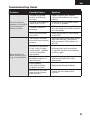
Inconsistent
ight
performance
Trim changes after
initial setup
If you adjust trim more than
8 clicks, select Relearn Servo
Settings in the Forward
Programming menu after landing
Changes to Sub-
Trim after initial
setup
If you need to trim the aircraft
during test ights, select Relearn
Servo Settings in the Forward
Programming menu after landing
Aircraft was not
kept immobile for
5 seconds after
battery connection
With the throttle stick in lowest
position. Disconnect battery, then
reconnect battery and keep the
aircraft still for 5 seconds.
Incorrect
response to the
AS3X Control
Direction Test
Incorrect direction
settings in the
receiver, which can
cause a crash
DO NOT y. Correct the direction
settings, then y.
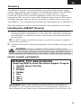
La page est en cours de chargement...
La page est en cours de chargement...
La page est en cours de chargement...
La page est en cours de chargement...
La page est en cours de chargement...
La page est en cours de chargement...
La page est en cours de chargement...
La page est en cours de chargement...
La page est en cours de chargement...
La page est en cours de chargement...
La page est en cours de chargement...
La page est en cours de chargement...
La page est en cours de chargement...
La page est en cours de chargement...
La page est en cours de chargement...
La page est en cours de chargement...
La page est en cours de chargement...
La page est en cours de chargement...
La page est en cours de chargement...
La page est en cours de chargement...
La page est en cours de chargement...
La page est en cours de chargement...
La page est en cours de chargement...
La page est en cours de chargement...
La page est en cours de chargement...
La page est en cours de chargement...
La page est en cours de chargement...
La page est en cours de chargement...
La page est en cours de chargement...
La page est en cours de chargement...
La page est en cours de chargement...
La page est en cours de chargement...
La page est en cours de chargement...
La page est en cours de chargement...
La page est en cours de chargement...
La page est en cours de chargement...
La page est en cours de chargement...
La page est en cours de chargement...
La page est en cours de chargement...
La page est en cours de chargement...
La page est en cours de chargement...
La page est en cours de chargement...
La page est en cours de chargement...
La page est en cours de chargement...
La page est en cours de chargement...
La page est en cours de chargement...
La page est en cours de chargement...
La page est en cours de chargement...
La page est en cours de chargement...
La page est en cours de chargement...
La page est en cours de chargement...
La page est en cours de chargement...
La page est en cours de chargement...
La page est en cours de chargement...
La page est en cours de chargement...
La page est en cours de chargement...
La page est en cours de chargement...
La page est en cours de chargement...
La page est en cours de chargement...
La page est en cours de chargement...
La page est en cours de chargement...
La page est en cours de chargement...
La page est en cours de chargement...
La page est en cours de chargement...
La page est en cours de chargement...
La page est en cours de chargement...
La page est en cours de chargement...
La page est en cours de chargement...
La page est en cours de chargement...
La page est en cours de chargement...
La page est en cours de chargement...
La page est en cours de chargement...
La page est en cours de chargement...
La page est en cours de chargement...
La page est en cours de chargement...
La page est en cours de chargement...
La page est en cours de chargement...
La page est en cours de chargement...
La page est en cours de chargement...
La page est en cours de chargement...
La page est en cours de chargement...
La page est en cours de chargement...
La page est en cours de chargement...
La page est en cours de chargement...
-
 1
1
-
 2
2
-
 3
3
-
 4
4
-
 5
5
-
 6
6
-
 7
7
-
 8
8
-
 9
9
-
 10
10
-
 11
11
-
 12
12
-
 13
13
-
 14
14
-
 15
15
-
 16
16
-
 17
17
-
 18
18
-
 19
19
-
 20
20
-
 21
21
-
 22
22
-
 23
23
-
 24
24
-
 25
25
-
 26
26
-
 27
27
-
 28
28
-
 29
29
-
 30
30
-
 31
31
-
 32
32
-
 33
33
-
 34
34
-
 35
35
-
 36
36
-
 37
37
-
 38
38
-
 39
39
-
 40
40
-
 41
41
-
 42
42
-
 43
43
-
 44
44
-
 45
45
-
 46
46
-
 47
47
-
 48
48
-
 49
49
-
 50
50
-
 51
51
-
 52
52
-
 53
53
-
 54
54
-
 55
55
-
 56
56
-
 57
57
-
 58
58
-
 59
59
-
 60
60
-
 61
61
-
 62
62
-
 63
63
-
 64
64
-
 65
65
-
 66
66
-
 67
67
-
 68
68
-
 69
69
-
 70
70
-
 71
71
-
 72
72
-
 73
73
-
 74
74
-
 75
75
-
 76
76
-
 77
77
-
 78
78
-
 79
79
-
 80
80
-
 81
81
-
 82
82
-
 83
83
-
 84
84
-
 85
85
-
 86
86
-
 87
87
-
 88
88
-
 89
89
-
 90
90
-
 91
91
-
 92
92
-
 93
93
-
 94
94
-
 95
95
-
 96
96
-
 97
97
-
 98
98
-
 99
99
-
 100
100
-
 101
101
-
 102
102
-
 103
103
-
 104
104


Spektrum AR8360T Manuel utilisateur
- Catégorie
- Jouets télécommandés
- Taper
- Manuel utilisateur
dans d''autres langues
- italiano: Spektrum AR8360T Manuale utente
- English: Spektrum AR8360T User manual
- Deutsch: Spektrum AR8360T Benutzerhandbuch
