
©Copyright 2018 Liberty Pumps Inc. All rights reserved
Installation Manual 7035000N
Heavy Duty Submersible Effluent/Dewatering Pumps
*Do not throw away or lose this manual.
Models
250-Series 1/3 HP
280-Series 1/2 HP
290-Series 3/4 HP
FL30-Series 1/3 HP
FL50-Series 1/2 HP
FLH60-Series 6/10 HP
FL60-Series 6/10 HP
FL70-Series 3/4 HP
FL100-Series 1 HP
FL150-Series 1-1/2 HP
FL200-Series 2 HP
Contents
Safety Information
General Information
Dewatering/Sump Applications
Effluent Applications
Electrical Service and Operation
Maintenance and Troubleshooting
Warranty
7000 Apple Tree Avenue
Bergen, NY 14416
Phone: (800) 543-2550
Fax: (585) 494-1839
www.libertypumps.com

©Copyright 2018 Liberty Pumps Inc. All rights reserved 2
1. Safety Information
This safety alert symbol in your manual and on the pump is intended to alert you
to a potential risk for injury or death.
This is a safety alert symbol identifying risk of electric shock. It will be accompa-
nied with an instruction intended to minimize your potential risk of electric shock.
This is a safety alert symbol identifying risk of fire. It will be accompanied with an
instruction intended to minimize your potential risk of fire.
This is a safety alert symbol identifying risk of injury or death. It will be accompa-
nied with an instruction intended to minimize your potential risk of injury or death.
Warns of hazards that will cause serious injury or death.
Warns of hazards that can or will cause minor or moderate injury.
Warns of hazards that can cause personal injury, death, or property damage.
Signals an important instruction related to the pump. Failure to follow these in-
structions could result in pump component failure, or improper operation of the
unit, possibly resulting in property damage .
NOTICE
DANGER
WARNING
CAUTION
ALWAYS disconnect the supplied pump(s) from their power sources before handling or making any adjustments to
either the pump(s), the pump system, or the control panel.
Only qualified personnel should complete fixed wiring and electrical connections, according to all local and national
electrical codes, during a pump system installation.
After installation, be certain that the pump is properly grounded, using its supplied grounding conductor. Failure to
properly ground the pump system can cause all metal portions of the pump and its surroundings to become ener-
gized.
During flood conditions, submerged electrical connections can energize the water. Always wear dielectric rubber
boots and other applicable Personal Protective Equipment (PPE) when water is on the floor and you must service an
energized pump system. DO NOT ENTER THE WATER if the water level is higher than that of the protection your
PPE offers or if your PPE is not watertight.
NEVER lift or carry a pump or a float assembly by its power cord. This will damage the power cord, and could ex-
pose the electrically live wires inside the power cord.
DO NOT bypass grounding wires.
The electrical power supply shall be located within the length limitations of the pump power cord, and for below
grade installations it shall be at least 1.22 m (4 ft) above the floor level.
NEVER use this product in applications where human contact with the pumped fluid is common (such as swimming
pools, fountains, marine areas, etc.).
RISK OF ELECTRIC SHOCK - Accidental contact with
electrically live parts, items, fluid, or water can cause serious in-
jury or death.
WARNING

©Copyright 2018 Liberty Pumps Inc. All rights reserved 3
During construction, if the pump system is installed before its power cord can be plugged in or direct wired, all power
cords must be protected from the environment to prevent water from wicking through the cord end into the pump or
switch housings. If water enters these housings, an electrical short can occur from the pump or switch to its sur-
roundings, which will energize the surroundings.
DO NOT use an extension cord to power the product. Extension cords can overload both the product and extension
cord supply wires. Overloaded wires will get very hot and can catch on fire.
This product requires a separate, properly fused and grounded branch circuit, sized for the voltage and amperage
requirements of the pump, as noted on the nameplate. Overloaded branch circuit wires will get very hot and can
catch on fire.
NEVER use this product with or near flammable liquids. If the rotating elements inside this pump strike any foreign
object, sparks may occur. Sparks could ignite flammable liquids.
This pump system must be installed in accordance with all applicable codes and ordinances.
DO NOT allow children to play with the pump system.
DO NOT allow children, or any person who is unqualified, to use this pump system. Any person who is unaware of
the dangers of this pump system, or whom has not read this manual, can easily be injured by the pump system.
Wear adequate PPE when working on pumps or piping that have been exposed to wastewater. Sump and sewage
pumps often handle materials which can transmit illness or disease upon contact with your skin and other tissues.
DO NOT remove any tags or labels from the pump or its cord.
NOTICE
RISK OF ELECTRIC SHOCK - continued
WARNING
RISK OF FIRE
WARNING
WARNING
RISK OF SERIOUS INJURY OR DEATH
NEVER dispose of materials such as paint thinner or other chemicals down drains. Doing so could chemically attack
and damage pump system components and cause product malfunction or failure.
DO NOT use pumps with fluid over 40°C. Operating the pump in fluid above this temperature can overheat the
pump, resulting in pump failure.
DO NOT use pump system with mud, sand, cement, oil or chemicals. Pump and system components can be dam-
aged from these items causing product malfunction or failure. Additionally, flooding can occur if these items jam the
impeller or piping.
DO NOT modify the pump system in any way. Modifications may affect seals, change the electrical loading of the
pump, or damage the pump and its components. Modifications can void your warranty on this product.
DO NOT run this pump system dry.

©Copyright 2018 Liberty Pumps Inc. All rights reserved 4
2. General Information
Note: Manual models (“M” suffix) and 3 phase models, as designated above, require a separate approved pump control device or panel for automatic operation.
Operation of these models will be according to the control selected. Make sure the electrical specifications of the control selected properly match the electrical
specifications of the pump. 3 phase models require overload elements selected or adjusted in accordance with the control or panel instructions.
WARNING: Always use a replacement power cord assembly of the same length and type as originally installed on the Liberty product. Using a cord of improper gauge or
length may lead to exceeding the electrical rating of the cord and could result in death, injury, fire or other significant failure.
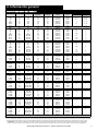
MODEL SPECIFICATIONS
Model HP Volts
Full Load
Amps
Solids
Handling
Automatic or
Manual
Shut-off
Head
Factory Switch Setting
Turn-on Turn-off
250* 1/3 115 5.2 1/2” Manual* 22 ft. * *
251 1/3 115 5.2 1/2” Automatic 22 ft. 11” 4-1/2”
253 1/3 115 5.2 1/2” Automatic 22 ft. 11” 4-1/2”
257 1/3 115 5.2 1/2” Automatic 22 ft. 7” 3-1/2”
250HV* 1/3 230 2.6 1/2” Manual* 22 ft. * *
251HV 1/3 230 2.6 1/2” Automatic 22 ft. 11” 4-1/2”
257HV 1/3 230 2.6 1/2” Automatic 22 ft. 7” 3-1/2”
280* 1/2 115 8.0 3/4” Manual* 37 ft. * *
281 1/2 115 8.0 3/4” Automatic 37 ft. 13” 7”
283 1/2 115 8.0 3/4” Automatic 37 ft. 13” 7”
287 1/2 115 8.0 3/4” Automatic 37 ft. 9-1/2” 4”
280HV* 1/2 208-230 4.0 3/4” Manual* 37 ft. * *
281HV 1/2 208-230 4.0 3/4” Automatic 37 ft. 13” 7”
283HV 1/2 208-230 4.0 3/4” Automatic 37 ft. 13” 7”
287HV 1/2 208-230 4.0 3/4” Automatic 37 ft. 9-1/2” 4”
290* 3/4 115 10.4 3/4” Manual* 48 ft. * *
291 3/4 115 10.4 3/4” Automatic 48 ft. 13” 7”
293 3/4 115 10.4 3/4” Automatic 48 ft. 13” 7”
297 3/4 115 10.4 3/4” Automatic 48 ft. 9-1/2” 4”
290HV* 3/4 208-230 5.3 3/4” Manual* 48 ft. * *
291HV 3/4 208-230 5.3 3/4” Automatic 48 ft. 13” 7”
293HV 3/4 208-230 5.3 3/4” Automatic 48 ft. 13” 7”
297HV 3/4 208-230 5.3 3/4” Automatic 48 ft. 9-1/2” 4”
FL31M* 1/3 115 10.5 3/4” Manual* 19 ft. * *
FL31A 1/3 115 10.5 3/4” Automatic 19 ft. 12” 5”
FL32M* 1/3 208-230 5.5 3/4” Manual* 19 ft. * *
FL32A 1/3 208-230 5.5 3/4” Automatic 19 ft. 12” 5”
FL51M* 1/2 115 12 3/4" Manual* 55 ft. * *
FL51A 1/2 115 12 3/4" Automatic 55 ft. 13” 6”
FL52M* 1/2 208-230 6.5 3/4" Manual* 55 ft. * *
FL52A 1/2 208-230 6.5 3/4" Automatic 55 ft. 13” 6”
FLH61M* 6/10 115 12 3/4” Manual* 70 ft. * *
FLH61A 6/10 115 12 3/4” Automatic 70 ft. 13” 6”
FL62M* 6/10 208-230 8.2 3/4" Manual* 65 ft. * *
FL62A 6/10 208-230 8.2 3/4" Automatic 65 ft. 13” 6”
FL63M* 6/10 208-230 3PH 5.6 3/4" Manual* 65 ft. * *
FL64M*
6/10 440-480 3PH
2.8
3/4" Manual* 65 ft. * *
FL72M* 3/4 208-230 10.5 3/4" Manual* 77 ft. * *
FL72A 3/4 208-230 10.5 3/4" Automatic 77 ft. 13” 6”
FL73M* 3/4 208-230 3PH 7.5 3/4" Manual* 77 ft. * *
FL74M* 3/4 440-480 3PH 3.5 3/4" Manual* 77 ft. * *
FL102M* 1 208-230 12 3/4” Manual* 90 ft. * *
FL102A 1 208-230 12 3/4” Automatic 90 ft. 15” 8”
FL103M* 1 208-230 3PH 9 3/4” Manual* 90 ft. * *
FL104M* 1 440-480 3PH 4.5 3/4” Manual* 90 ft. * *
FL105M* 1 575 3PH 3.3 3/4” Manual* 90 ft. * *
FL152M* 1-1/2 208-230 15 3/4” Manual* 110 ft. * *
FL152A 1-1/2 208-230 15 3/4” Automatic 110 ft. 15” 8”
FL153M* 1-1/2 208-230 3PH 10.6 3/4” Manual* 110 ft. * *
FL154M* 1-1/2 440-480 3PH 5.3 3/4” Manual* 110 ft. * *
FL155M* 1-1/2 575 3PH 4.9 3/4” Manual* 110 ft. * *
FL202M* 2 208-230 15 3/4” Manual* 130 ft. * *
FL202A 2 208-230 15 3/4” Automatic 130 ft. 15” 8”
FL203M* 2 208-230 3PH 10.6 3/4” Manual* 130 ft. * *
FL204M* 2 440-480 3PH 5.3 3/4” Manual* 130 ft. * *
FL205M* 2 575 3PH 4.9 3/4” Manual* 130 ft. * *

©Copyright 2018 Liberty Pumps Inc. All rights reserved 5
3. Dewatering / Sump Applications
1. For ordinary ground water pumping applications, a sump pit of not less than 14" in diameter is recommended.
Vertical float (VMF) models (257, 287 and 297) may be used in a minimum 10" diameter sump; however, a larger
diameter pit is preferred as it allows for a longer pump cycle and reduced switch cycling. The minimum depth of
the pit should be 18".
2. If the pit is not already enclosed on the bottom, provide a hard level bottom of bricks or concrete. DO NOT place
the pump directly on earth, gravel or debris since this can cause excessive wear of the impeller and possible
jamming. “The Brick” (sold by Liberty Pumps as part # 4445000) is a pre-molded stable platform designed to fit
your submersible pump. It raises the pump 2.5” off the bottom of the pit, reducing the potential for jamming from
rocks and debris. Contact your local distributor to order. Remove all debris from the bottom of the sump pit
before installation of the pump. A sump pit cover is suggested for safety and to prevent foreign objects from
entering the pit.
3. Set the pump in the pit making sure the switch has adequate clearance and will not hang-up on the pit wall. The
float must be free to move throughout its travel and not contacting the pump body, piping, or other objects. A 1-
1/2" threaded discharge is provided for connection of the discharge pipe. Do not reduce the discharge size to
below 1-1/2”. Schedule 40 PVC pipe is recommended; however, flexible discharge hose kits may be used for
temporary installations.
4. Connect the pipe or the discharge hose to the discharge of the pump. HAND TIGHTEN ONLY. Over tightening
may cause the pump housing to crack. Install a union or other means of separating the discharge line just above
the floor to facilitate removal of the pump if necessary. A check valve is recommended just above or in place of
the union to prevent the backflow of water after each pump cycle. (All Liberty effluent/dewatering pumps come
equipped with an air bleed hole in the base of the pump to help prevent airlock. A small spray of water from this
hole is normal while pump is running.)
5. Connect additional piping as needed to direct the discharge to the desired location. Discharge should be kept as
short as possible with a minimum number of turns. Check all connections for security.
6. Install a union or other means of separating the discharge pipe just above the floor to facilitate removal of the
pump if necessary. A check valve is recommended just above, or in place of, the union to prevent the backflow of
water after each pump cycle.
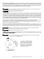
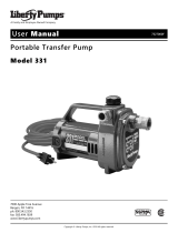
7. If a check valve is used, a 1/8” anti-airlock hole should be drilled in the discharge pipe just above the
pump’s discharge outlet to prevent pump “airlock” (see Fig. 1).
8. For added protection, consider the addition of a back-up pump such as Liberty’s SJ10 SumpJet, as well as an
alarm such as Liberty’s ALM-2 in applications where loss of pump function could result in property damage.
If an alarm is used, it must be connected to a separate electrical circuit.
Drill 1/8” anti-airlock
hole.
Water spray is normal.
Fig. 1 – Anti-airlock hole position

©Copyright 2018 Liberty Pumps Inc. All rights reserved 6
4. Effluent Applications
Vertical Magnetic Float (VMF) models (257, 287 and 297) are not recommended for effluent applications due to their
short On/Off cycle. Wide angle float models are better suited for effluent applications and are easily adjustable for
different On/Off levels.
The basin required for effluent applications must be sealed and vented to meet health and plumbing code requirements.
Proper basin size and basin materials for effluent applications vary depending on the type of effluent system and local
codes. Check with your local codes official prior to purchasing and installing the basin. Follow the manufacturer's
recommended guidelines for installation of your specific basin. A minimum diameter of 18" and depth of 24" is required
for proper pump operation, but larger basins are preferred for longer pump cycles and increased switch life. Installation
should be at a sufficient depth to ensure that all plumbing is below the frost line. If this is not feasible, delete the check
valve and size the basin and/or adjust the pump differential to accommodate the additional backflow.
These pumps are not to be installed in locations
classified as hazardous in accordance with the
National Electric Code, ANSI/NFPA 70, or where
prohibited by local codes.
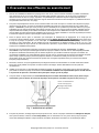
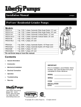
A. Simplex (One Pump) Systems (see Fig. 2): Set the pump in place
making sure the float has adequate clearance to the side wall of the
basin. The float must be free to move throughout its travel and not
contacting the pump body, piping, or other objects. If an optional
control device or float is used, follow the directions for mounting that
accompany the optional control. Connect the discharge pipe to the
pump's threaded discharge. IMPORTANT: DO NOT REDUCE THE
DISCHARGE PIPE SIZE BELOW THAT WHICH IS PROVIDED ON
THE PUMP. Contact Liberty Pumps or other qualified person if you
have questions regarding proper pipe sizes and flow rates.
Mount the basin cover making sure it is properly sealed.
Installation of Discharge: After the pump has been
mounted, install the discharge line. A union should be
installed to facilitate pump removal if necessary. A free-flow
swing check valve is recommended after the union to
prevent the backflow of liquid after each pumping cycle. A
gate valve should follow the check valve to allow periodic
cleaning of the check valve or removal of the pump. The
remainder of the discharge line should be as short as
possible with a minimum number of turns, to minimize
friction head loss. Contact Liberty Pumps or other qualified
person if you have questions regarding proper pipe sizes
and flow rates.
(All Liberty effluent/dewatering pumps come equipped with
an air bleed hole in the base of the pump to help prevent
airlock. A small spray of water from this hole is normal
while pump is running.)
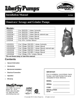
B. Duplex (Two Pump) Systems (see Fig. 3): Set both
pumps in place in the bottom of the basin. The duplex
control used will include 3 or 4 floats that will either be
tethered to one of the discharge pipes or to an independent
rod or bracket. Follow the instructions provided with your
duplex control device. Each float must be free to move
throughout its travel and not contacting the pump
body, piping, or other objects. Connect an individual
discharge pipe to each pump.
Fig. 2 – Typical Installation Simplex System
This is a recommended installation only.
Variations may apply.
Fig. 3 – Typical Installation Duplex System
This is a recommended installation only.
Variations may apply.

©Copyright 2018 Liberty Pumps Inc. All rights reserved 7
IMPORTANT: DO NOT REDUCE THE DISCHARGE PIPE SIZE BELOW THAT WHICH IS PROVIDED ON THE PUMP.
Contact Liberty Pumps or other qualified person if you have any questions regarding proper pipe sizes and flow rates.
To eliminate fluid recycling in duplex installations, it is necessary to have a check valve on each discharge line prior to
tying the two discharges into one common line. Depending on the height of your basin, the check valves may either be
installed inside the basin or outside the basin. Mount the basin cover(s) making sure they are properly sealed.
Installation of Remaining Discharge: Unions or flexible connectors should be installed to facilitate removal of
the pump if necessary. Free-flow swing check valves should be installed on each discharge after the union and prior to
the gate valve to prevent the back flow of liquid or gas. A check valve on each discharge line, prior to tying into one
common line, is necessary to prevent the recycling of fluid from one pump to the other. A gate valve is recommended
after the check valve to allow for periodic cleaning of the check valve or removal of the pump. The remainder of the dis-
charge line should be as short as possible with a minimum number of turns to minimize friction head loss. Contact Liber-
ty Pumps or other qualified person if there are questions regarding proper pipe size or flow rates. (All Liberty effluent/
dewatering pumps come equipped with an air bleed hole in the base of the pump to help prevent airlock. A small spray
of water from this hole is normal while pump is running.)
5. Electrical Service and Operation
Risk of electric shock. Always disconnect the pump from the power source before handling or making adjustments.
The electrical connections and wiring for a pump installation should only be made by qualified personnel.
This pump is supplied with a grounding conductor or a grounding type attachment plug. To reduce the risk of
electric shock, be certain that the grounding conductor is connected only to a properly grounded control panel or, if
equipped with a grounding type plug that it is connected to a properly grounded, grounding type receptacle.
DO NOT bypass grounding wires or remove ground prongs from attachment plugs.
DO NOT use an extension cord.
This pump requires separate, properly fused and grounded branch circuit. Make sure the power source is properly
sized for the voltage and amperage requirements of the motor, as noted on the pump nameplate.
The electrical outlet or panel shall be within the length limitations of the pump power cord, and at least 4 feet above
floor level to minimize possible hazards from flood conditions.
The installation must be in accordance with the National Electric Code and all applicable local codes and
ordinances.
When the risk of property damage from high water levels exists, an independent high water alarm or
back up pump system should be installed.
All FL-Series automatic models (designated with the letter "A") and Models 253, 283 and 293, come factory-equipped
with a float switch mounted to the pump. These models come with two cords - one to the float switch and the other to
the pump motor. The switch cord has a series (piggyback) plug enabling the pump (motor) cord to be plugged into the
back of it. The purpose of this design is to allow manual operation of the pump.
For manual operation, or in the event of switch failure, the pump cord can be separated and plugged into the
electrical outlet, directly bypassing the switch (see Fig. 4).
DON’T!
Fig. 1 Piggyback plug installation.
TEMPORARY
MANUAL
OPERATION
NORMAL
Fig. 4 – Temporary manual operation

©Copyright 2018 Liberty Pumps Inc. All rights reserved 8
For automatic operation using Liberty's supplied switch, the two cords should be interconnected and plugged
into a separately fused grounded outlet of proper amp capacity for your selected pump model. (See Section 1, General
Information or the pump nameplate for electrical specifications of your model.) Both cords are equipped with 3-prong
plugs and must be plugged into a properly grounded 3-wire receptacle. DO NOT REMOVE THE GROUND PRONGS.
208-230V single phase pumps shall only be operated without the float switch by using the circuit
breaker or panel disconnect.
Do not let the pump run dry.
The turn-on/turn-off levels vary depending on model. (See model specifications chart on page 3 for the "factory" preset
level of your specific model.) Other pumping differentials may be obtained by tethering the switch cord to the discharge
pipe. NOTE: A minimum cord length of 3-1/2" from the tether point to the top surface of the float is required for proper
switch operation. If using a differential other than the factory setting, be sure that when the pump shuts off, at least
3-1/2" of fluid is left in the basin so the impeller remains submerged. (Models 251, 257, 281, 287, 291, and 297 have
factory-preset switches that are not adjustable.)
Manual pumps with no switch are intended to be run using an approved liquid level control or approved motor control
with correct rating that matches motor input in full load amperes. Regardless of the control type, be sure that when the
pump shuts off, at least 3-1/2" of fluid is left in the basin so the impeller remains submerged.
NOTE: For automatic operation with optional control devices: If the pump(s) are to be operated by either a
simplex or duplex control panel or other optional control device, follow the installation instructions provided with the
control and make the power connections per those instructions. If necessary, certain models may be run without a
separate control.
208-230V single phase pumps shall only be operated without the float switch by using the circuit
breaker or panel disconnect.
Do not let the pump run dry.
3 Phase Pump Models (FL63, FL64, FL73, FL74, FL103, FL104, FL105, FL153, FL154, FL155,
FL203, FL204, FL205)
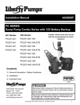
For 3-Phase pumps, check for proper rotation before installing pump into basin (see Fig. 5).
Bottom View
Check three phase pumps for proper
rotation prior to installing pump(s) in
basin. To change rotation, reverse any
two of the three power leads to the
pump. Code the wires for reconnection
after installation.
Fig. 5 – Proper impeller rotation,
three phase models

©Copyright 2018 Liberty Pumps Inc. All rights reserved 9
If a single phase pump is to be wired directly into a control device or junction box, and it is necessary to remove the
plugs, have a certified electrician do the wiring in accordance with the National Electric Code and applicable local codes.
See Fig. 6 for direct wire installation of single phase, automatic pumps.
Fig. 6 – Direct Wiring of 120V or 208-230V Single
Phase, Automatic Pump(s)
For 208-230V installations: Install a double pole disconnect near the pump installation. One
side of the line going to the pump is always “hot”, whether the float switch is in the “On” or the “Off”
position. Use of a double pole disconnect will allow both hot legs to be de-energized.
6. Maintenance
Risk of electric shock. Always disconnect the pump from the power source before
handling or making adjustments.
Always disconnect the pump from power source before handling. This guide is designed
to help identify reasons for potential operating problems. It is not a service guide. Dismantling of
pump voids warranty. Servicing of pump other than simple cleaning of pump inlet or
impeller should be referred to the factory or its authorized service centers.
1. Submersible Models: Submersible pump models have sealed permanently lubricated bearings and
require no additional lubrication.
2. Pump should be checked frequently for debris and/or build up which may interfere with pump or float
switch operation. The float must be able to move freely through its complete travel without any
restrictions. Pour enough water into the sump to activate the pump periodically (at least every 3 months) when
not normally in use to verify proper function.
NOTE: The manufacturer assumes no responsibility for damage or injury due to disassembly in the field.

©Copyright 2018 Liberty Pumps Inc. All rights reserved 10
7. Troubleshooting
Problem Cause Correcon
Pump will not run.
Blown fuse or other interrupon of
power; improper voltage.
Check that the unit is securely plugged in. Have
an electrician check all wiring for proper
connecons and adequate voltage and capacity.
Switch is unable to move to the “turn
on” posion due to interference with
the side of basin or other obstrucon
Position the pump or switch so that it has
adequate clearance for free operation.
Insufficient liquid level.
Make sure the liquid level is allowed to rise
enough to activate switch(s).
Defecve switch.
Remove and replace switch.
Pump will not turn
off.
Switch(s) unable to move to the
“turn off” position due to
interference with the side of basin
or other obstacle.
Position the pump or switch so that it has
adequate clearance for free operation.
Defective switch. Remove and replace switch.
Pump runs or
hums, but does not
pump.
Discharge is blocked or restricted.
Check the discharge line for foreign material,
including ice if the discharge line passes
through or into cold areas.
Check valve is stuck closed or installed
backwards.
Remove check valve(s) and examine for freedom
of operaon and proper installaon.
Gate or ball valve is closed. Open gate or ball valve.
Total li is beyond pump's capability.
Try to route piping to a lower level. If not
possible, a larger pump may be required.
Consult the factory.
Pump impeller is jammed or volute
casing is plugged.
*Remove the pump from the basin. Detach
the pump base and clean the area around
the impeller. Reassemble and reinstall.
Pump runs
periodically when
fixtures are not in
use.
Check valve was not installed, is stuck
open or is leaking.
Remove check valve(s) and examine for freedom
of operaon and proper installaon.
Fixtures are leaking.
Repair fixtures as required to eliminate
leakage.
Pump operates
noisily.
Foreign objects in the impeller
cavity.
*Remove the pump from the basin. Detach
the pump base and clean the area around
the impeller. Reassemble and reinstall.
Broken impeller.
Consult the factory for information regarding
replacement of impeller.
Worn bearings.
Return pump to the factory or authorized
repair station for repair.
Piping attachments to building are
too rigid.
Replace a portion of the discharge line with
rubber hose or connector.

©Copyright 2018 Liberty Pumps Inc. All rights reserved 11
8. 3 Year Limited Warranty
*NOTE: Liberty Pumps, Inc. assumes no responsibility for damage or injury due to disassembly in the field.
Disassembly, other than at Liberty Pumps or its authorized service centers, automatically voids warranty.
Liberty Pumps, Inc. warrants that pumps of its manufacture are free from all factory defects in material and workmanship
for a period of 3 years from the date of purchase. The date of purchase shall be determined by a dated sales receipt
noting the model and serial number of the pump. The dated sales receipt must accompany the returned pump if the date
of return is more than 3 years from the "CODE" (date of manufacture) number noted on the pump nameplate.
The manufacturer's obligation under this warranty shall be limited to the repair or replacement of any parts found by the
manufacturer to be defective, provided the part or assembly is returned freight prepaid to the manufacturer or its
authorized service center, and provided that none of the following warranty-voiding characteristics are evident.
The manufacturer shall not be liable under this warranty if the product has not been properly installed; if it has been
disassembled, modified, abused or tampered with; if the electrical cord has been cut, damaged or spliced; if the pump
discharge has been reduced in size; if the pump has been used in water temperatures above the advertised rating, or
water containing sand, lime, cement, gravel or other abrasives; if the product has been used to pump chemicals or
hydrocarbons; if a non-submersible motor has been subjected to excessive moisture; or if the label bearing the serial,
model and code number has been removed. Liberty Pumps, Inc. shall not be liable for any loss, damage or expenses
resulting from installation or use of its products, or for consequential damages, including costs of removal, reinstallation
or transportation.
There is no other express warranty. All implied warranties, including those of merchantability and fitness for a particular
purpose, are limited to three years from the date of purchase.
This warranty contains the exclusive remedy of the purchaser, and, where permitted, liability for consequential or
incidental damages under any and all warranties are excluded.
7000 Apple Tree Avenue
Bergen, NY 14416
Phone: (800) 543-2550
Fax: (585) 494-1839
www.libertypumps.com

©Copyright 2018 Liberty Pumps Inc. Todos los derechos reservados
Manual de instalación 7035000N
Bombas de efluentes/desagüe sumergibles de alta resistencia
*No tire ni pierda este manual.
Modelos
Serie 250 1/3 HP
Serie 280 1/2 HP
Serie 290 3/4 HP
Serie FL30 1/3 HP
Serie FL50 1/2 HP
Serie FLH60 6/10 HP
Serie FL60 6/10 HP
Serie FL70 3/4 HP
Serie FL100 1 HP
Serie FL150 1-1/2 HP
Serie FL200 2 HP
Contenido
Información de seguridad
Información general
Aplicaciones de desagüe/sumidero
Aplicaciones de efluentes
Servicio y operación eléctricos
Mantenimiento y diagnóstico de
problemas
Garantía
7000 Apple Tree Avenue
Bergen, NY 14416
Teléfono: (800) 543-2550
Fax: (585) 494-1839
www.libertypumps.com
Al instalador: Deje este manual con el
propietario / operador para referencia futura.
Antes de la instalación, registrar el modelo, el
número de serie y el código de la placa de la
bomba, y guardar para futuras consultas.
MODELO:____________________________
NO. DE SERIE:________________________

©Copyright 2018 Liberty Pumps Inc. Todos los derechos reservados 2
1. Información de Seguridad
Este símbolo de alerta de seguridad en el manual y la bomba está pensado para
avisarle del riesgo potencial de una lesión o la muerte.
Este símbolo de alerta de seguridad identifica el riesgo de descarga eléctrica. Se
acompaña con una instrucción destinada a minimizar el riesgo de una descarga
eléctrica.
Este símbolo de alerta de seguridad identifica el riesgo de incendio. Se acompaña
con una instrucción destinada a minimizar el riesgo de un incendio.
Este símbolo de alerta de seguridad identifica el riesgo de una lesión o la muerte. Se
acompaña con una instrucción destinada a minimizar el riesgo potencial de una
lesión o la muerte.
Advierte peligros que provocarán lesiones graves o la muerte.
Advierte peligros que podrían provocar o provocarán lesiones menores o
moderadas.
Advierte peligros que pueden provocar lesiones personales, la muerte o daños a la
propiedad.
Indica una instrucción importante con relación a la bomba. El incumplimiento de estas
instrucciones puede provocar fallos en los componentes de la bomba, o el
funcionamiento incorrecto de la unidad, y posiblemente resulte en daños a la propiedad.
AVISO
PELIGRO
ADVERTENCIA
PRECAUCIÓN
Desconectar SIEMPRE la(s) bomba(s) suministrada(s) de la fuente de alimentación antes de manipular o hacer
ajustes a la(s) bomba(s), el sistema de bombeo o el panel de control.
Sólo el personal calificado debe completar el cableado fijo y las conexiones eléctricas, de acuerdo con todos los
códigos eléctricos locales y nacionales cuando se instale un sistema de bombeo.
Después de la instalación, asegúrese de que la bomba está conectada a tierra correctamente, utilizando su
conductor de puesta a tierra suministrado. No poner a tierra correctamente el sistema de bombeo podría electrizar
todas las piezas metálicas de la bomba y su entorno.
Durante una inundación, las conexiones eléctricas sumergidas podrían electrizar el agua. Usar siempre botas de
goma con propiedades dieléctricas y otros Equipos de Protección Personal (EPP) cuando haya agua en el piso y
deba prestar servicio y encender el sistema de bombeo. NO ENTRAR EN EL AGUA si el nivel del agua sobrepasa
la altura de la protección que ofrece su EPP o si su EPP no es a prueba de agua.
NO levantar NI transportar NUNCA una bomba o un ensamblaje de flotación tirando de su cable de alimentación.
Esto dañará el cable de alimentación y podría exponer los cables con corriente eléctrica que van por dentro del
cable de alimentación.
NO derivar los cables de conexión a tierra.
La fuente de alimentación eléctrica debe encontrarse dentro de los límites de longitud del cable de alimentación de
la bomba, y en caso de instalaciones por debajo del nivel del suelo necesitará encontrarse como mínimo 1,22 m
(4 pies) por encima del piso.
NO usar NUNCA este producto en aplicaciones en las que el contacto humano con el líquido bombeado sea común
RIESGO DE DESCARGA ELÉCTRICA: El contacto
accidental con piezas, elementos, líquidos o agua eléctricamente
activos puede provocar lesiones graves o la muerte.
ADVERTENCIA

©Copyright 2018 Liberty Pumps Inc. Todos los derechos reservados 3
Durante una construcción, si el sistema de bombeo debe instalarse antes de que se pueda enchufar o conectar
directamente a su cable de alimentación, todos los cables de alimentación deberán protegerse contra los elementos de la
intemperie para evitar que el agua se absorba a través del extremo del cable que entra en la bomba o en las cajas de los
interruptores. Si entra agua en estos recintos podría producirse un cortocircuito eléctrico desde la bomba o caja de
conexiones, lo que podría electrizar su entorno.
NO usar cables de extensión de alimentación eléctrica con el producto. Los cables de extensión pueden sobrecargar tanto
el producto como los cables de alimentación del extendedor. Los cables sobrecargados aumentan de temperatura y
pueden incendiarse.
Este producto requiere un circuito de derivación independiente bien soldado y conectado a tierra, que corresponda con el
voltaje y el amperaje de la bomba, tal como se indica en la placa. Si los cables del circuito de derivación se sobrecargan
aumentarán de temperatura y podrían incendiarse.
NO usar NUNCA este producto con líquidos inflamables o cerca de ellos. Si los elementos rotatorios dentro de la bomba
golpean un objeto extraño, se pueden producir chispas. Las chispas pueden encender líquidos inflamables.
Este sistema de bomba debe instalarse de acuerdo con todos los códigos y reglamentos aplicables.
NO se debe permitir que los niños jueguen con el sistema de bombeo.
NO se debe permitir que un niño o una persona no calificada utilice el sistema de bombeo. Una persona que no conozca
los peligros de este sistema de bombeo o que no haya leído este manual, podría fácilmente sufrir una lesión con el
sistema de bombeo.
Se debe llevar el EPP adecuado cuando se trabaje con bombas o tuberías expuestas a aguas residuales. Los sumideros
y las bombas de aguas residuales a menudo transportan materiales que pueden transmitir infecciones y enfermedades al
entrar en contacto con la piel y otros tejidos.
AVISO
RIESGO DE DESCARGA ELÉCTRICA - continuación
ADVERTENCIA
RIESGO DE INCENDIO
ADVERTENCIA
ADVERTENCIA
RIESGO DE UNA LESIÓN GRAVE O LA MUERTE
No se debe verter NUNCA materiales como diluyentes de pintura y otros productos químicos en los desagües. Hacerlo
podría causar una reacción química y dañar los componentes del sistema de bombeo, lo que causaría el mal
funcionamiento o la avería del producto.
NO se debe usar la bomba con líquidos que sobrepasen los 40°C. Poner a funcionar la bomba en un líquido que
sobrepasa esta temperatura puede sobrecalentar la bomba y averiar la bomba.
NO se debe usar el sistema de bombeo con lodo, arena, cemento, petróleo ni productos químicos. La bomba y los
componentes podrían dañarse por causa de estos materiales, lo que causaría el mal funcionamiento o la avería del
producto. Además, se podría producir una inundación si estos materiales atascan el rotor o la tubería.
NO se debe modificar el sistema de bombeo de ninguna manera. Las modificaciones podrían afectar los sellos, alterar la
carga eléctrica de la bomba, o dañar la bomba y sus componentes. Las modificaciones podrían anular la garantía de este
producto.
NO se debe poner en marcha el sistema de bombeo en seco.

©Copyright 2018 Liberty Pumps Inc. Todos los derechos reservados 4
2. Información general
* Nota: Los modelos manuales (con sufijo "M") y los modelos trifásicos, según se designaron anteriormente, requieren de un dispositiv o o panel de control de bombas aprobado separa-
do para el accionamiento automático. El accionamiento de estos modelos dependerá del control seleccionado. Asegúrese de que las especificaciones eléctricas del control seleccionado correspondan
con las especificaciones eléctricas de la bomba. Los modelos trifásicos requieren de elementos de sobrecarga seleccionados o ajustados de acuerdo con las instrucciones del control o panel.
ADVERTENCIA: Al usar un cable de alimentación de repuesto, asegúrese de que tenga la misma longitud y sea del mismo tipo que el cable instalado originalmente en el producto Liberty.
Un cable con calibre o longitud incorrectos podría llevar a que se excedan los valores eléctricos nominales del cable y provocar la muerte, lesiones, incendios u otros fallos significativos.
ESPECIFICACIONES DEL MODELO
Modelo HP Voltios
Amperios a
carga total
Manipulación
de sólidos
Automático o
manual
Presión de
cierre
Ajuste de interruptor de fábrica
Encendido Apagado
250* 1/3 115 5.2 1/2” Manual* 22 pies * *
251 1/3 115 5.2 1/2” Automático 22 pies 11” 4-1/2”
253 1/3 115 5.2 1/2” Automático 22 pies 11” 4-1/2”
257 1/3 115 5.2 1/2” Automático 22 pies 7” 3-1/2”
250HV* 1/3 230 2.6 1/2” Manual* 22 pies * *
251HV 1/3 230 2.6 1/2” Automático 22 pies 11” 4-1/2”
257HV 1/3 230 2.6 1/2” Automático 22 pies 7” 3-1/2”
280* 1/2 115 8.0 3/4” Manual* 37 pies * *
281 1/2 115 8.0 3/4” Automático 37 pies 13” 7”
283 1/2 115 8.0 3/4” Automático 37 pies 13” 7”
287 1/2 115 8.0 3/4” Automático 37 pies 9-1/2” 4”
280HV* 1/2 208-230 4.0 3/4” Manual* 37 pies * *
281HV 1/2 208-230 4.0 3/4” Automático 37 pies 13” 7”
283HV 1/2 208-230 4.0 3/4” Automático 37 pies 13” 7”
287HV 1/2 208-230 4.0 3/4” Automático 37 pies 9-1/2” 4”
290* 3/4 115 10.4 3/4” Manual* 48 pies * *
291 3/4 115 10.4 3/4” Automático 48 pies 13” 7”
293 3/4 115 10.4 3/4” Automático 48 pies 13” 7”
297 3/4 115 10.4 3/4” Automático 48 pies 9-1/2” 4”
290HV* 3/4 208-230 5.3 3/4” Manual* 48 pies * *
291HV 3/4 208-230 5.3 3/4” Automático 48 pies 13” 7”
293HV 3/4 208-230 5.3 3/4” Automático 48 pies 13” 7”
297HV 3/4 208-230 5.3 3/4” Automático 48 pies 9-1/2” 4”
FL31M* 1/3 115 10.5 3/4” Manual* 19 pies * *
FL31A 1/3 115 10.5 3/4” Automático 19 pies 12” 5”
FL32M* 1/3 208-230 5.5 3/4” Manual* 19 pies * *
FL32A 1/3 208-230 5.5 3/4” Automático 19 pies 12” 5”
FL51M* 1/2 115 12 3/4" Manual* 55 pies * *
FL51A 1/2 115 12 3/4" Automático 55 pies 13” 6”
FL52M* 1/2 208-230 6.5 3/4" Manual* 55 pies * *
FL52A 1/2 208-230 6.5 3/4" Automático 55 pies 13” 6”
.
FLH61M* 6/10 115 12 3/4” Manual* 70 pies * *
FLH61A 6/10 115 12 3/4” Automático 70 pies 13” 6”
FL62M* 6/10 208-230 8.2 3/4" Manual* 65 pies * *
FL62A 6/10 208-230 8.2 3/4" Automático 65 pies 13” 6”
FL63M* 6/10 208-230 3PH 5.6 3/4" Manual* 65 pies * *
FL64M*
6/10 440-480 3PH
2.8
3/4" Manual* 65 pies * *
FL72M* 3/4 208-230 10.5 3/4" Manual* 77 pies * *
FL72A 3/4 208-230 10.5 3/4" Automático 77 pies 13” 6”
FL73M* 3/4 208-230 3PH 7.5 3/4" Manual* 77 pies * *
FL74M* 3/4 440-480 3PH 3.5 3/4" Manual* 77 pies * *
FL102M* 1 208-230 12 3/4” Manual* 90 pies * *
FL102A 1 208-230 12 3/4” Automático 90 pies 15” 8”
FL103M* 1 208-230 3PH 9 3/4” Manual* 90 pies * *
FL104M* 1 440-480 3PH 4.5 3/4” Manual* 90 pies * *
FL105M* 1 575 3PH 3.3 3/4” Manual* 90 pies * *
FL152M* 1-1/2 208-230 15 3/4” Manual* 110 pies * *
FL152A 1-1/2 208-230 15 3/4” Automático 110 pies 15” 8”
FL153M* 1-1/2 208-230 3PH 10.6 3/4” Manual* 110 pies * *
FL154M* 1-1/2 440-480 3PH 5.3 3/4” Manual* 110 pies * *
FL155M* 1-1/2 575 3PH 4.9 3/4” Manual* 110 pies * *
FL202M* 2 208-230 15 3/4” Manual* 130 pies * *
FL202A 2 208-230 15 3/4” Automático 130 pies 15” 8”
FL203M* 2 208-230 3PH 10.6 3/4” Manual* 130 pies * *
FL204M* 2 440-480 3PH 5.3 3/4” Manual* 130 pies * *
FL205M* 2 575 3PH 4.9 3/4” Manual* 130 pies * *

©Copyright 2018 Liberty Pumps Inc. Todos los derechos reservados 5
3. Aplicaciones de desagüe / sumidero
1. Para aplicaciones ordinarias de bombeo de agua subterránea, se recomienda un sumidero con un mínimo de 14"
de diámetro. Se pueden usar los modelos de flotador vertical (VMF) (257, 287 y 297) en un sumidero con un
mínimo de 10" de diámetro; sin embargo, se prefiere una fosa de diámetro mayor, ya que permite un ciclo de
bombeo más prolongado y un ciclo de conmutación reducido. La profundidad mínima de la fosa debe ser de 18".
2. Si la fosa no está ya confinada en el fondo, construya un fondo duro de ladrillos u hormigón. NO coloque la
bomba directamente sobre la tierra, grava o el escombro, ya que esto puede provocar desgaste excesivo del
rotor y posiblemente ocasione un atoramiento. «The Brick» (vendido por Liberty Pumps como pieza No. 4445000)
es una plataforma estable premoldeada diseñada para adaptarse a su bomba sumergible. Eleva la bomba 2.5"
sobre el fondo de la fosa, lo que reduce la posibilidad de atoramiento debido a piedras o escombro.
Comuníquese con su distribuidor local para pedirlo. Retire todo escombro del fondo del sumidero antes de
instalar la bomba. Se recomienda una cubierta para sumidero por motivos de seguridad y para prevenir que
entren objetos extraños en la fosa.
3. Coloque la bomba en la fosa, asegurándose de que el interruptor tenga el espacio suficiente y que no se atorará
en la pared de la fosa. El flotador debe tener libertad de movimiento en su recorrido y no hacer contacto con el
cuerpo de la bomba, la tubería u otros objetos. Se proporciona una conexión de descarga enroscada de 1-1/2"
para conectar con el tubo de descarga. No reduzca el tamaño de la conexión de descarga a menos de 1-1/2". Se
recomienda un tubo de PVC cédula 40; sin embargo, para instalaciones temporales es posible usar los juegos de
manguera de descarga flexible.
4. Conecte el tubo o la manguera de descarga a la conexión de descarga de la bomba. APRIETE A MANO
ÚNICAMENTE. Si aprieta demasiado, podría provocar que la carcasa de la bomba se agriete. Instale una unión u
otro medio para separar el conducto de descarga justo arriba del piso a fin de facilitar el retiro de la bomba en
caso de que fuese necesario. Se recomienda una válvula de retención justo arriba o en lugar de la unión con el
fin de impedir el contraflujo del agua después de cada ciclo de bombeo. (Todas las bombas de efluentes/desagüe
Liberty vienen equipadas con un agujero de purga de aire en la base para impedir un bloqueo por aire. Durante el
accionamiento de la bomba, es normal que salga un pequeño rocío de agua de este agujero.)
5. Conecte la tubería adicional, según sea necesario, para dirigir la descarga al sitio deseado. La descarga debe ser
lo más corta posible, con un mínimo de giros. Por motivos de seguridad, revise todas las conexiones.
6. Instale una unión u otro medio para separar el tubo de descarga justo arriba del piso a fin de facilitar el retiro de
la bomba en caso de que fuese necesario. Se recomienda una válvula de retención justo arriba o en lugar de la
unión con el fin de impedir el contraflujo del agua después de cada ciclo de bombeo.
7. Si se usa una válvula de retención, se debe taladrar un agujero contra bloqueo por aire de 1/8" en el tubo de
descarga, justo arriba de la salida de descarga de la bomba, a fin de impedir el bloqueo por aire (consulte
la fig. 1).
8. Para mayor protección, considere añadir una bomba de respaldo, como el SumpJet SJ10 de Liberty, así como
una alarma, como la ALM-2 de Liberty, en aplicaciones en que la pérdida de la función de bombeo pudiera
ocasionar daños materiales. Si se usa una alarma, ésta debe conectarse a un circuito eléctrico separado.
Taladre un
agujero contra
bloqueo por aire
de 1/8".
El rocío de agua
es normal.
Fig. 1 – Anti-airlock hole position

©Copyright 2018 Liberty Pumps Inc. Todos los derechos reservados 6
4. Aplicaciones de efluentes
No se recomiendan los modelos de flotador magnético vertical (VMF) (257, 287 y 297) para las aplicaciones de efluentes,
debido a que su ciclo de activado/desactivado es muy breve. Los flotadores de ángulo ancho son mejores para las
aplicaciones de efluentes y se ajustan fácilmente a los diferentes niveles de activado/desactivado.
La fosa requerida para las aplicaciones de efluentes debe estar sellada y ventilada para cumplir con los requisitos del código
de salud y plomería. El tamaño y los materiales adecuados de la fosa para las aplicaciones de efluentes varían en función del
tipo de sistema de efluentes y los códigos locales. Consulte con el funcionario de códigos locales antes de comprar e instalar
la fosa. Siga las pautas recomendadas por el fabricante al instalar su fosa particular. Se requiere como mínimo un diámetro
de 18" y una profundidad de 24" para el funcionamiento correcto de la bomba, pero se prefieren fosas mayores para los ciclos
de bombeo más largos y para una vida útil más larga del interruptor. La instalación se deberá realizar a una profundidad
suficiente como para que todas las tuberías queden por debajo de la línea de penetración de la helada. Si esto no es posible,
elimine la válvula de retención y modifique el tamaño de la fosa o ajuste el diferencial de la bomba para dar cabida al
contraflujo adicional.
Estas bombas no deberán instalarse en sitios
clasificados como peligrosos en conformidad con la
National Electric Code ANSI/NFPA 70, o donde lo
A. Sistemas simples (una bomba) (consulte la fig. 2): Coloque la
bomba y asegúrese de que el flotador tenga la distancia suficiente con
las paredes de la fosa. El flotador debe tener libertad de movimiento en
su recorrido y no hacer contacto con el cuerpo de la bomba, la
tubería u otros objetos. Si se usa un dispositivo de control o flotador
opcional, siga las direcciones de montaje que acompañan al control
opcional. Conecte el tubo de descarga a la conexión de descarga
enroscada en la bomba. IMPORTANTE: NO REDUZCA EL TAMAÑO
DEL TUBO DE DESCARGA MÁS DEL QUE YA TIENE EN LA BOMBA.
Comuníquese con Liberty Pumps u otra persona cualificada si tiene
alguna pregunta acerca de los tamaños adecuados del tubo y sobre las
velocidades de flujo. Monte la cubierta de la fosa y asegúrese de que
esté sellada correctamente.
Instalación de la descarga : Una vez montada la bomba,
instale el conducto de descarga.Se deberá instalar una unión a
fin de facilitar el retiro de la bomba, si fuera necesario. Se
recomienda una válvula de retención tipo columpio y de flujo
libre después de la union para impedir el contraflujo del líquido
después de cada ciclo de bombeo. Después de la válvula de
retención debe haber una válvula de tajadera para permitir la
limpieza periódica de la válvula de retención o el retiro de la
bomba. El resto del conducto de descarga debe ser lo más
corto posible y con un mínimo de giros a fin de minimizar la
pérdida de presión por fricción. Comuníquese con Liberty
Pumps u otra persona cualificada si tiene alguna pregunta
acerca de los tamaños adecuados del tubo y sobre las
velocidades de flujo.
(Todas las bombas de efluentes/desagüe Liberty vienen
equipadas con un agujero de purga de aire en la base para
impedir un bloqueo por aire. Durante el accionamiento de la
bomba, es normal que salga un pequeño rocío de agua de este
agujero.)
B. Sistemas doble (dos bombas) (consulte la fig. 3): Coloque
ambas bombas en su lugar, al fondo de la fosa. El control doble
usado incluirá 3 o 4 flotadores que estarán atados a uno de los
tubos de descarga o a una varilla o soporte independiente. Siga
las instrucciones provistas con su dispositivo de control doble.
Cada uno de los flotadores debe tener libertad de movimiento
en su recorrido y no hacer contacto con el cuerpo de la
bomba, la tubería u otros objetos. Conecte un tubo de descarga
individual a cada bomba.
Fig. 2 – Instalación típica de sistema simple
Esto es únicamente una instalación recomendada.
Pueden Presentarse variaciones.
ADVERTENCIA
CONDUCTO
ELÉCTRICO
CHIMENEA DE VENTILACIÓN
(OPCIONAL)
ENTRADA
VÁLVULA DE
RETENCIÓN
UNIÓN
VÁLVULA DE
TAJADERA
DESCARGA
ENTRADA
FLO-
TADOR
ES DE
CON-
TROL
Fig. 3 – Instalación típica de sistema doble
Esto es únicamente una instalación recomendada.
Pueden presentarse variaciones.
CONDUCTO
ELÉCTRICO
CHIMENEA DE
VENTILACIÓN
OPCIONAL
VÁLVULAS DE
RETENCIÓN
CONEXIÓN
EN T
UNIONES
VÁLVULAS DE
TAJADERA
BOMBAS
DESCARGA ENTRADA
FLOTADORES
DE CONTROL

©Copyright 2018 Liberty Pumps Inc. Todos los derechos reservados 7
IMPORTANTE: NO REDUZCA EL TAMAÑO DEL TUBO DE DESCARGA MÁS DEL QUE YA TIENE EN LA BOMBA. Comuníquese
con Liberty Pumps u otra persona cualificada si tiene alguna pregunta acerca de los tamaños adecuados del tubo y sobre las
velocidades de flujo. Para eliminar el reciclado de fluido en instalaciones doble, es necesario tener una válvula de retención en cada
conducto de descarga antes de unir las dos descargas y formar un conducto común. En función de la altura de la fosa, es posible
instalar las válvulas de retención en el interior de la fosa o el exterior. Monte la o las cubiertas de la fosa y asegúrese de que estén
selladas correctamente.
Instalación de la descarga restante: Se deben instalar uniones o conectores flexibles para facilitar el retiro de la bomba, si
fuera necesario. Se deben instalar válvulas de retención tipo columpio y de flujo libre en cada descarga después de la unión y antes
de la válvula de tajadera a fin de impedir el contraflujo del líquido o gas. Para impedir el reciclado de fluido de una bomba a otra, es
necesario tener una válvula de retención en cada conducto de descarga antes de unir las dos descargas y formar un conducto
común. Se recomienda una válvula de tajadera después de la válvula de retención para permitir la limpieza periódica de la válvula de
retención o el retiro de la bomba. El resto del conducto de descarga debe ser lo más corto posible y tener un mínimo de giros a fin de
minimizar la pérdida de presión por fricción. Comuníquese con Liberty Pumps u otra persona cualificada si tiene alguna pregunta
acerca del tamaño de tubo adecuado y sobre las velocidades de flujo. (Todas las bombas de efluentes/desagüe Liberty vienen
equipadas con un agujero de purga de aire en la base para impedir un bloqueo por aire. Durante el accionamiento de la bomba, es
normal que salga un pequeño rocío de agua de este agujero.)
5. Servicio eléctrico y accionamiento
Riesgo de descarga eléctrica. Desconecte la bomba del suministro eléctrico siempre que vaya a manipularla o a realizar
algún ajuste.
Solo personal cualificado deberá encargarse de instalar las conexiones y los cables eléctricos necesarios para montar la bomba.
La bomba viene con un conductor de puesta a tierra o un enchufe con descarga a tierra. Para reducir el riesgo de descargas
eléctricas, asegúrese de que el conductor de puesta a tierra esté conectado únicamente a un panel de control adecuadamente
puesto a tierra o, si viene con un enchufe de descarga a tierra, que esté conectado a un receptáculo adecuadamente puesto a tierra.
NO derive los cables de conexión a tierra ni retire las espigas de los enchufes.
NO use cables de extensión.
Con esta bomba hay que utilizar un circuito derivado independiente, debidamente conectado tierra y con fusibles adecuados.
Asegúrese que la fuente de alimentación tenga suficiente capacidad para cumplir los requisitos de tensión y amperaje del motor,
según se indica en la placa de la bomba.
La toma de corriente o el panel deberá encontrarse al alcance del cable de alimentación de la bomba y a 4 pies como mínimo
por encima del nivel del suelo para evitar problemas en caso de inundación.
Si existe el riesgo de daños materiales debido a niveles elevados de agua, se debe instalar una alarma de
aguas altas o un sistema de bombeo de respaldo independiente.
Todos los modelos automáticos de la serie FL (designados con la letra «A») y los modelos 253, 283 y 293 vienen con un interruptor
de flotador preinstalado en la bomba. Estos modelos vienen con dos cables: uno que va dirigido al interruptor de flotador y otro que
va al motor de la bomba. El cable del interruptor tiene un enchufe en serie que permite que el cable (del motor) de la bomba se
enchufe en la parte posterior del mismo. La finalidad de este diseño es posibilitar el accionamiento manual de la bomba.
Para el accionamiento manual, o en caso de un fallo del interruptor, el cable de la bomba puede separarse y enchufarse en
el tomacorrientes, y circunvalar directamente el interruptor (consultar fig. 4).
¡NO!
Fig. 1 Piggyback plug installation.
TEMPORAL
ACCIONAMIEN
TO MANUAL
NORMAL
Fig. 4 – Accionamiento manual temporal
ADVERTENCIA
CAUTION

©Copyright 2018 Liberty Pumps Inc. Todos los derechos reservados 8
Para el accionamiento automático con el interruptor suministrado por Liberty, los dos cables deben interconectarse y
enchufarse en un tomacorrientes independiente, puesto a tierra y con fusible que tenga la capacidad de amperios adecuada
para el modelo de bomba seleccionado. (Consulte la Sección 1, Información general o la placa de la bomba para conocer las
especificaciones eléctricas de su modelo.) Ambos cables vienen equipados con enchufes de 3 clavijas y deben enchufarse en
un tomacorrientes con puesta a tierra. NO RETIRE LAS CLAVIJAS DE PUESTA A TIERRA.
Las bombas monofásicas de 208-230 V se accionarán únicamente sin el interruptor de flotador usando el
disyuntor o el interruptor de desconexión del panel.
No permita que la bomba se accione en seco.
Los niveles de activado/desactivado variarán en función del modelo. (Consulte el gráfico con las especificaciones del modelo
en la página 3 para conocer el nivel predeterminado en fábrica de su modelo particular.) Es posible obtener otros diferenciales
de bombeo al atar el cable del interruptor al tubo de descarga. NOTA: Se requiere de un cable con una longitud mínima de
3-1/2" desde el punto de sujeción hasta la superficie superior del flotador para una operación de conmutación adecuada. Si
utiliza un diferencial distinto a la determinada en la fábrica, asegúrese de que cuando la bomba se desactive quede al menos
3-1/2" de fluido en la fosa a fin de que el rotor permanezca sumergido. (Los modelos 251, 257, 281, 287, 291, y 297 cuentan
con interruptores preconfigurados en fábrica y que no se pueden ajustar.)
Las bombas manuales sin interruptor fueron diseñadas para funcionar con un control de nivel de líquido aprobado o un control
de motor aprobado, y con la tensión correcta que corresponda a la entrada del motor en amperios a plena carga.
Independientemente del tipo de control, asegúrese de que cuando la bomba se desactive quede al menos 3-1/2" de fluido en
la fosa a fin de que el rotor permanezca sumergido.
NOTA: Para el accionamiento automático con dispositivos de control opcionales: Si la o las bombas se accionan con
un panel de control simple o doble u otro dispositivo de control opcional, siga las instrucciones de instalación provistas con el
control y realice las conexiones eléctricas de acuerdo con dichas instrucciones. Si es necesario, es posible accionar ciertos
Las bombas monofásicas de 208-230 V se accionarán únicamente sin el interruptor de flotador
usando el disyuntor o el interruptor de desconexión del panel.
No permita que la bomba se accione en seco.
3 Modelos de bomba trifásicos (FL63, FL64, FL73, FL74, FL103, FL104, FL105, FL153, FL154,
FL155, FL203, FL204, FL205)
En el caso de las bombas trifásicas, compruebe que la rotación vaya en la dirección correcta antes
de instalarlas en la fosa (consulte la fig. 5).
Vista inferior
Si se trata de una bomba trifásica,
compruebe que la rotación vaya en la
dirección correcta antes de instalarla en
la fosa. Para cambiar la rotación,
invierta dos de los tres latiguillos de
alimentación de la bomba. Marque los
cables después de la instalación para
poder volver a conectarlos.
Fig. 5 – Giro correcto del rotor,
modelos trifásicos
ADVERTENCIA
CAUTION
ADVERTENCIA
CAUTION
CAUTION

©Copyright 2018 Liberty Pumps Inc. Todos los derechos reservados 9
Si se va a cablear una bomba monofásica directamente a un dispositivo de control o caja de empalmes, y es necesario
eliminar los enchufes, busque que un electricista certificado efectúe el cableado de acuerdo con la National Electric Code y los
códigos locales correspondientes. Consulte la fig. 6 para conocer el cableado directo de bombas automáticas monofásicas.
Fig. 6 – Cableado directo de bomba(s) automática(s)
monofásicas de 120 V o 208-230 V
Para instalaciones de 208-230 V: Instale un interruptor de desconexión bipolar. El lado del conducto
que va a la bomba está siempre «vivo», sea que el conmutador de flotador esté en la posición de
«activado» o «desactivado». El uso de un interruptor de desconexión bipolar permitirá desenergizar ambas
6. Mantenimiento
Riesgo de descarga eléctrica. Desconecte la bomba de la fuente de alimentación siempre que
vaya a manipularla o a realizar algún ajuste.
Desconecte la bomba de su fuente de alimentación siempre que vaya a manipularla. Esta guía
está diseñada para ayudar a identificar las causas de posibles problemas en el accionamiento. No es
una guía de servicio. Desmantelar la bomba anula la garantía. El servicio de mantenimiento de la
bomba que no sea una simple limpieza de la entrada de la bomba o del rotor deberá reservarse para
1. Modelos sumergibles: Los modelos de bombas sumergibles tienen cojinetes sellados y lubricados de
modo permanente, de modo que no requieren de lubricación adicional.
2. Es necesario verificar frecuentemente que no haya escombro o acumulación que pudiera interferir con
la operación de la bomba o del interruptor del flotador. El flotador debe tener movimiento libre durante
todo su recorrido, sin restricción alguna. Vierta agua suficiente en el sumidero para activar la bomba
periódicamente (al menos cada 3 meses), fuera de su uso normal, con la finalidad de verificar su
NOTA: El fabricante no asume ninguna responsabilidad de los daños o las lesiones producidos por el
ADVERTENCIA
ADVERTENCIA
ADVERTENCIA
FUENTE DE
ALI-
MENTACIÓN
A TIERRA
VERDE
BLANCO
NEGRO
NEGRO
CAJA DE EMPALMES
NEGRO
VERDE
BLANCO
BLANCO
INTER-
RUPTOR
DE PEDAL
BOMBA
La page charge ...
La page charge ...
La page charge ...
La page charge ...
La page charge ...
La page charge ...
La page charge ...
La page charge ...
La page charge ...
La page charge ...
La page charge ...
La page charge ...
La page charge ...
-
 1
1
-
 2
2
-
 3
3
-
 4
4
-
 5
5
-
 6
6
-
 7
7
-
 8
8
-
 9
9
-
 10
10
-
 11
11
-
 12
12
-
 13
13
-
 14
14
-
 15
15
-
 16
16
-
 17
17
-
 18
18
-
 19
19
-
 20
20
-
 21
21
-
 22
22
-
 23
23
-
 24
24
-
 25
25
-
 26
26
-
 27
27
-
 28
28
-
 29
29
-
 30
30
-
 31
31
-
 32
32
-
 33
33


dans d''autres langues
Documents connexes
-
Liberty Pumps LE51A Manuel utilisateur
-
Liberty Pumps LEH102A2 Guide d'installation
-
 Liberty Pumps 331 Manuel utilisateur
-
 Liberty Pumps PRG101A Mode d'emploi
-
 Liberty Pumps LSGX203M Guide d'installation
-
Liberty Pumps 237 Mode d'emploi
-
 Liberty Pumps PC237-442-10A Mode d'emploi
-
Liberty Pumps 404L Mode d'emploi
-
Liberty Pumps ALM-P1 Mode d'emploi
-


