GE AZ45E07EAC Le manuel du propriétaire
- Catégorie
- Climatiseurs split-system
- Taper
- Le manuel du propriétaire

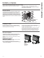
Write the model and serial
numbers here:
Model # _________________
Serial # _________________
Find these numbers on a label
behind the room cover on the
base pan.
GE is a trademark of the General Electric Company. Manufactured under trademark license.
OWNER’S MANUAL
AIR CONDITIONER
Zoneline
®
49-7774-2 02-18 GEA
SAFETY INFORMATION .........3
USING THE ZONELINE
Controls ..............................6
Air Direction ..........................7
To Remove the Room Cover ............7
Ventilation Control .....................7
Auxiliary Controls ......................8
Remote Thermostat ...................12
Makeup Air ..........................13
CARE AND CLEANING
Base Pan ............................14
Outdoor Coils ........................14
Room Cover and Case .................14
Ventilation Filter ......................15
Air Filters ............................15
INSTALLATION INSTRUCTIONS
Preparation ..........................16
Replacing an Existing Unit .............17
Electrical Connection ..................18
Installing the Zoneline .................21
Optional Drain Kit ....................23
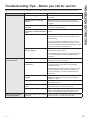
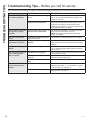
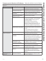
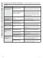
TROUBLESHOOTING TIPS ..... 24
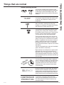
Normal Operating Sounds ............ 26
CONSUMER SUPPORT
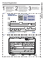
Ownership Registration ................27
Warranty ............................31
Consumer Support ....................32
AZ45
AZ65
ESPAÑOL
For a Spanish version of this
manual, visit our Website at
www.zoneline.com.
Para consultar una version
en español de este manual
de instrucciones, visite nuestro
sitio de internet
www.zoneline.com.
FRANÇAIS
For a French version of this
manual, visit our Website at
www.zoneline.com.
Pour un version français de
ce manuel d’utilisation, veuillez
visiter notre site web à l’adresse
www.zoneline.com.

2 49-7774-2
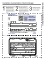
THANK YOU FOR MAKING GE APPLIANCES A PART OF YOUR HOME.
Whether you grew up with GE Appliances, or this is your first, we’re happy to have you in the family.
We take pride in the craftsmanship, innovation and design that goes into every GE Appliances
product, and we think you will too. Among other things, registration of your appliance ensures that we
can deliver important product information and warranty details when you need them.
Register your GE appliance now online. Helpful websites and phone numbers are available in the
Consumer Support section of this Owner’s Manual. You may also mail in the pre-printed registration
card included in the packing material.

49-7774-2 3
READ AND SAVE THESE INSTRUCTIONS
IMPORTANT SAFETY INFORMATION
READ ALL INSTRUCTIONS BEFORE USING THE APPLIANCE
SAFETY INFORMATION
For your safety, the information in this manual must be followed to minimize the risk of fire or
explosion, electric shock, or to prevent property damage, personal injury, or loss of life.
SAFETY PRECAUTIONS
WARNING
Ŷ7KLV=RQHOLQHPXVWEHSURSHUO\LQVWDOOHGLQDFFRUGDQFHZLWKWKH,QVWDOODWLRQ,QVWUXFWLRQVEHIRUHLWLV
XVHG6HHWKH,QVWDOODWLRQ,QVWUXFWLRQVLQWKHEDFNRIWKLVPDQXDO
Ŷ,PPHGLDWHO\UHSODFHDOOHOHFWULFVHUYLFHFRUGVWKDWKDYHEHFRPHIUD\HGRURWKHUZLVHGDPDJHG$
damaged power supply cord must be replaced with a new power supply cord obtained from the
manufacturer and not repaired. Do not use a cord that shows cracks or abrasion damage along its
length or at either the plug or connector end.
Ŷ8QSOXJRUGLVFRQQHFWWKH=RQHOLQHDWWKHIXVHER[RUFLUFXLWEUHDNHUEHIRUHPDNLQJDQ\UHSDLUV
NOTE: We strongly recommend that any servicing be performed by a qualified individual.
Ŷ7KHVH5$DLUFRQGLWLRQLQJV\VWHPVUHTXLUHFRQWUDFWRUVDQGWHFKQLFLDQVWRXVHWRROVHTXLSPHQW
and safety standards approved for use with this refrigerant. DO NOT use equipment certified for
R22 refrigerant only.
Replacing an existing unit?
)RUGHWDLOVVHHWKH,QVWDOODWLRQ,QVWUXFWLRQVLQWKLVPDQXDO

49-7774-2
SAFETY INFORMATION
LIRE ET CONSERVER CES INSTRUCTIONS
CONSIGNES DE SÉCURITÉ IMPORTANTES
LISEZ TOUTES LES INSTRUCTIONS AVANT L’UTILISATION
Pour votre sécurité, veuillez observer les consignes de ce manuel afin de réduire le risque d’incendie,
d’explosion, de choc électrique, de dommages à la propriété ou de blessures, graves ou fatales.
MESURES DE SÉCURITÉ
Ŷ$YDQWVRQXWLOLVDWLRQFHFOLPDWLVHXU=RQHOLQHGRLWrWUHLQVWDOOpFRUUHFWHPHQWHQFRQIRUPLWpDYHFOHV
instructions d’installation. Consultez les instructions d’installation au dos de ce manuel.
Ŷ5HPSODFH]LPPpGLDWHPHQWWRXVOHVFRUGRQVpOHFWULTXHVXVpVRXDXWUHPHQWHQGRPPDJpV8QFRUGRQ
pOHFWULTXHHQGRPPDJpQHGRLWSDVrWUHUpSDUpLOGRLWrWUHUHPSODFpSDUXQFRUGRQQHXIDFTXLVDXSUqV
GXIDEULFDQW1¶XWLOLVH]SDVXQFRUGRQTXLSUpVHQWHGHVILVVXUHVRXGHVPDUTXHVG¶DEUDVLRQVXUVD
ORQJXHXUVDILFKHRXVDFRQQH[LRQ
Ŷ'pEUDQFKH]OHFOLPDWLVHXU=RQHOLQHRXFRXSH]OHFRXUDQWjODERvWHGHIXVLEOHVRXDXGLVMRQFWHXU
DYDQWG¶HIIHFWXHUXQHUpSDUDWLRQ
REMARQUE: 1RXVUHFRPPDQGRQVYLYHPHQWTXHOHVUpSDUDWLRQVVRLHQWHIIHFWXpHVSDUXQHSHUVRQQH
TXDOLILpHHQODPDWLqUH
Ŷ/HVRXWLOVOHVpTXLSHPHQWVHWOHVQRUPHVGHVpFXULWpXWLOLVpVSDUOHVHQWUHSUHQHXUVHWOHVWHFKQLFLHQV
GRLYHQWrWUHDSSURXYpVHQIRQFWLRQGXIOXLGHIULJRULJqQHGRQWOHV\VWqPHGHFOLPDWLVDWLRQ5$GX
=RQHOLQHHVWpTXLSpN’UTILISEZ PAS d’équipements certifiés relativement au fluide frigorigène
R22 seulement.
Vous remplacez un climatiseur existant?
Pour de plus amples renseignements, veuillez consulter les instructions d’installation de ce manuel.
AVERTISSEMENT

49-7774-2 5
SAFETY INFORMATION
LEA Y GUARDE ESTAS INSTRUCCIONES
INFORMACIÓN IMPORTANTE DE SEGURIDAD
LEA TODAS LAS INSTRUCCIONES ANTES DE USAR
Para su seguridad, se debe seguir la información de este manual para minimizar el riesgo de
incendio o explosión, descargas eléctricas, o para evitar daños a la propiedad, lesiones personales
o la muerte.
PRECAUCIONES DE SEGURIDAD
Ŷ$QWHVGHLQLFLDUVXXVRHODFRQGLFLRQDGRUGHDLUH=RQHOLQHGHEHLQVWDODUVHFRUUHFWDPHQWHVHJ~QODV
,QVWUXFFLRQHVGHLQVWDODFLyQ9HUODV,QVWUXFFLRQHVGHLQVWDODFLyQHQODSDUWHWUDVHUDGHHVWHPDQXDO
Ŷ5HHPSODFHLQPHGLDWDPHQWHWRGRVORVFDEOHVHOpFWULFRVTXHVHKD\DSHODGRRTXHVHKD\DQGDxDGR
GHDOJXQDRWUDPDQHUD8QFDEOHGHFRUULHQWHGDxDGRQRGHEHUHSDUDUVHVLQRTXHGHEHVHU
VXVWLWXLGRSRUXQRQXHYRTXHVHDGTXLHUDGHOIDEULFDQWH1RXVHXQFDEOHHOpFWULFRTXHPXHVWUH
HYLGHQFLDVGHGHWHULRURRGDxRVGHDEUDVLyQHQVXVXSHUILFLHRHQFXDOTXLHUDGHVXVHQFKXIHVR
H[WUHPRV
Ŷ'HVHQFKXIHRGHVFRQHFWHHO=RQHOLQHGHVGHODFDMDGHIXVLEOHVRHOGLV\XQWRUDQWHVGHUHDOL]DU
FXDOTXLHUWLSRGHUHSDUDFLyQ
NOTA: 5HFRPHQGDPRVHQpUJLFDPHQWHTXHFXDOTXLHUVHUYLFLROOHYDGRDFDERHQHVWHHTXLSRORUHDOLFH
un individuo calificado.
Ŷ/RVVLVWHPDVGHDFRQGLFLRQDGRUGHDLUH5$UHTXLHUHQTXHORVFRQWUDWLVWDV\WpFQLFRVXWLOLFHQ
herramientas, equipamiento y normas de seguridad aprobadas para su uso con este refrigerante.
NO utilice equipamiento certificado sólo para refrigerante R22.
¿Desea reemplazar una unidad ya instalada?
3DUDPiVGHWDOOHVYHUODV,QVWUXFFLRQHVGHLQVWDODFLyQHQHVWHPDQXDO
ADVERTENCIA

6 49-7774-2
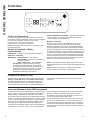
USING THE ZONELINE
Controls
About Your Heat Pump (AZ65 only)
Heat pumps can save money by removing heat from the
outside air—even when the outside temperature is below
freezing—and releasing that heat indoors.
7RJHWWKHEHVWHQHUJ\SHUIRUPDQFHIURP\RXUKHDWSXPS
don’t change the room thermostat by more than one degree
at one time. Raising the heat setting 2–3 degrees will cause
WKH=RQHOLQHWRXVHLWVHOHFWULFKHDWLQJHOHPHQWVLQRUGHUWR
reach the new temperature setting quickly.
7KHHOHFWULFKHDWLQJHOHPHQWVXVHPRUHHOHFWULFLW\WKDQKHDW
pumps and cost more to operate.
7KHUHLVDPLQXWHPLQLPXPFRPSUHVVRUUXQWLPHDWDQ\
setting to prevent short cycling.
7KHIDQVVWDUWEHIRUHWKHFRPSUHVVRUDQGVWRSDIWHUWKH
compressor cycles off.
When the outdoor temperature is lower than 25°F, heat is
provided by the electric heater instead of by the heat pump.
When the outdoor temperature is lower than 35°F,
cooling operation is locked out to prevent damage to the
compressor. Operation will resume when the outdoor
WHPSHUDWXUHULVHVDERYH)
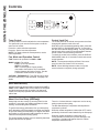
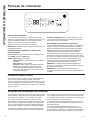
Temp Control
7KHWHPSFRQWUROLVXVHGWRPDLQWDLQWKHURRPWHPSHUDWXUH
7KHV\VWHPZLOOF\FOHRQDQGRIIWRNHHSWKHURRPDWWKH
same level of comfort.
Press the + pad to raise the temperature.
Press the - pad to lower the temperature.
NOTE: 7KHGLVSOD\VKRZVWKHVHWWHPSHUDWXUHQRWWKH
room temperature.
Fan, Mode and Operation Control
FAN—Sets the fan operation for HIGH or LOW.
MODE— COOL—For cooling
FAN—For fan-only operation
HEAT—For heating
OFF—7XUQVWKHXQLWRII3RZHUUHPDLQV
FRQQHFWHGWRWKH=RQHOLQH7KH)UHH]H+HDW
Sentinel features still function if active. See the
Freeze/Heat Sentinel section on page 8.
USE WALL THERMOSTAT—7KLV/('ZLOOOLJKWXSZKHQ
the unit is controlled by a wall thermostat. See page 9 for
details.
Control Lock Out
7KHFRQWUROSDQHOFDQEHORFNHGRXWWRSUHYHQWXVHUVIURP
changing the operation mode of the unit.
While the unit is in the desired operating mode, press and
KROGWKH',63/$<6+2:+,'(EXWWRQIRUVHFRQGVWR
lock the control and the desired setting. Any key press after
WKDWZLOOUHVXOWLQWKHPRGH/('DQGWHPSHUDWXUHWKDWZDV
locked to flash 5 times and then go dormant.
7RXQORFNWKHFRQWUROORFNRXWIHDWXUHSUHVVWKH',63/$<
6+2:+,'(EXWWRQIRUVHFRQGVWRXQORFNDQGUHVXPH
normal operation.
NOTE: The temperature display will flash if the control
panel is locked (see Control Lock Out section).
NOTE: When switching between modes, it may take
several minutes to completely change operation.
Quick Heat Recovery
Activates each time the thermostat is switched from OFF or
COOL mode to HEAT mode. Electric heaters are energized
until the thermostat set point is reached. On heat pump
PRGHOVWKHKHDWSXPSRSHUDWLRQZLOOUHVXPHDWWKHQH[W
call for heat.

49-7774-2 7
Using the Zoneline
USING THE ZONELINE
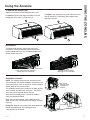
Ventilation Control*
NOTE: Two shipping screws must be removed from the
vent door before use. See the Installation Instructions in the
back of this manual. If you do not plan to use the ventilation
feature, leave the two screws in place.
7KHYHQWLODWLRQFRQWUROOHYHULVORFDWHGDWWKHORZHUOHIWVLGH
RIWKH=RQHOLQHXQLWEHKLQGWKHURRPFRYHU7KHSRVLWLRQ
RIWKHOHYHUFDQEHDGMXVWHGZLWKWKHZLQJQXW
When set at the closed position, only the air inside the
room is circulated and filtered.
When set in an open position, some outdoor air will be
GUDZQLQWRWKHURRP7KLVZLOOUHGXFHWKHKHDWLQJRUFRROLQJ
efficiency.
Energy Tip: Keep the vent control in the closed position to
prevent unconditioned air from entering the room.
* Not on Make Up Air Module
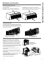
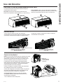
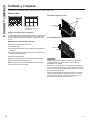
Air Direction
7RFKDQJHWKHDLUGLUHFWLRQUHPRYHWKHURRPFRYHU
5HPRYHWKHORXYHUVFUHZVWKDWKROGWKHORXYHULQVHUW
LQSODFH5RWDWHWKHORXYHUUHLQVWDOODQGUHSODFHWKH
screws and the room cover.
To Remove the Room Front
Additional controls are located behind the room cover.
To remove: Pull out at the bottom to release it from the
KROGLQJWDEVRQWKHVLGHV7KHQOLIWXS
To replace: Align and place the top rail of the room cover
RYHUWKHFKDVVLV3XVKLQZDUGDWWKHERWWRPXQWLOLW
VQDSVLQWRSODFH
Remove the
shipping screws
(if operation is
GHVLUHG
/RXYHUVFUHZV
)DFWRU\6KLSSHG/RXYHU2ULHQWDWLRQ
DLUIORZ#IURPKRUL]RQWDO
0RGLILHG/RXYHU2ULHQWDWLRQ
DLUIORZ#IURPKRUL]RQWDO
9HQW&RQWURO

8 49-7774-2
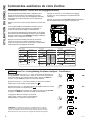
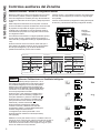
Auxiliary controls on your Zoneline
USING THE ZONELINE
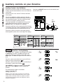
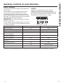
Auxiliary Controls - Aux Set Button
While the unit is preset to what most customers prefer, the
DX[LOLDU\FRQWUROVORFDWHGEHKLQGWKHURRPFRYHUEHORZWKH
control panel.
5HPRYHWKHURRPFRYHU6HHWKH7R5HPRYHWKH5RRP
Cover section.
,IWKHRZQHUPRGLILHVWKHDX[LOLDU\FRQWUROVLWLVWKHQWKH
RZQHULVUHVSRQVLEOHIRUHQVXULQJWKHDX[LOLDU\FRQWUROVDUH
VHWWRWKHGHVLUHGIXQFWLRQ7KHUHDUHGLIIHUHQWPRGHV
WKDWFDQEHVHWXVLQJWKHDX[LOLDU\VHWEXWWRQ
7RFKDQJHRSHUDWLQJRUVHWXSSDUDPHWHUVILUVWJRWRWKH
mode control and turn the unit off, then, press the red
AUX SETEXWWRQ³$8´DSSHDUVRQWKHGLVSOD\
Press the mode button on the control pad until the first digit
in the display shows the number corresponding to the mode
\RXDUHFKRRVLQJDQGWKHFRUUHFW+($7&22//('LVOLW
Press the +/- button to make the mode setting selection
ZKHUHDSSOLFDEOHVKRZQLQWKHVHFRQGGLJLWRIWKHGLVSOD\
Press the red AUX SET button to lock in the selection, and
H[LW$8;6(7PRGH
Red
$X[6HW
Button
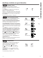
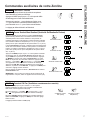
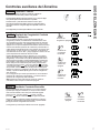
MODE 1
Smart Fan—Cooling/Heating
Press MODE XQWLODDSSHDUVLQWKHILUVWGLJLWRIWKHGLVSOD\
for Smart FanFRROPRGH7KHCOOL/('OLJKWRQWKH
PDLQFRQWUROZLOOEHRQ7RFKDQJHWRKHDWPRGHSUHVV
MODE DJDLQ7KHHEAT/('OLJKWRQWKHPDLQFRQWUROZLOO
be lit.
3UHVVWKHSDGWRVHWWKHLQGRRUIDQWRF\FOHRQRIILQWKH
heating or cooling mode selected “ ´
Press the + pad to set the indoor fan to run continuously in
the heating or cooling mode selected “ ´
Press AUX SETWRFRQILUP\RXUVHOHFWLRQDQGH[LWAUX
SET mode, or press MODE to continue setting other
functions.
7KHGHIDXOWVHWWLQJIRU0RGHLVDVIROORZV
&RROLQJ&RQWLQXRXV21
+HDWLQJ&\FOH2))
*Note:,QF\FOLFFRROLQJPRGHWKHLQGRRUIDQZLOODFWLYDWH
RFFDVLRQDOO\WRYHULI\DLUWHPSHUDWXUHLQWKHURRP,QF\FOLF
heating mode, the fan will continue to operate for several
seconds after the heating function has stopped in order to
increase unit efficiency.
(AZ65 Only)
(AZ65 Only)
Temperature
Limit
Class 2
Mode
Duct Mode *
All I2R Mode
Boost Heat
Press “Aux Set”
First Digit Second Digit
Press “Mode” Press +
/
-
Makeup Air
Mode *
Makeup Air
Occupancy *
Press “Aux Set”
First Digit Second Digit
Press “Mode” Press
0: OFF
1: 25CFM
2: 30CFM
3: 35CFM
Disable
293D2203P003
Enable
+
/
-
Off On
Press “Aux Set”
First Digit
Press “Mode”
Second Digit
Press
- Cycle - Continue
+
/
-
Smart Fan
Temperature
Display
Sentinel
Constant
Fan
Off On
4: 40CFM
5: 45CFM
6: 50CFM
Off On (Cool/Heat) On (Auto Change Over)
Engineering
Revision*
Press +/- to match last
digit of model number
* Not available on all models.

49-7774-2 9
Auxiliary controls on your Zoneline
USING THE ZONELINE
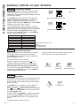
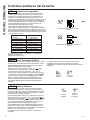
MODE 2
Fahrenheit / Celsius
7KLVIHDWXUHDOORZVWKHLQGLYLGXDOWRVZLWFKWKH
temperature units between Fahrenheit and Celsius on
the display.
Press MODE until a 2 appears in the first digit of the
GLVSOD\IRU)DKUHQKHLW&HOVLXVPRGH
Press the - pad to select Celsius or the + pad to select
)DKUHQKHLW7KHLQGLYLGXDOZLOOVHHDQ)IRU)DKUHQKHLWRU
a C for Celsius in the second digit of the display based
on the selection.
7KHGHIDXOWVHWWLQJIRU0RGHLV)DKUHQKHLW
° F
° C
MODE 3
Freeze Sentinel/Heat Sentinel
With power to the unit and Freeze Sentinel activated,
the unit automatically provides heat without user
LQWHUIDFH7KLVSUHYHQWVSRWHQWLDOSOXPELQJGDPDJHE\
WXUQLQJWKHKHDWHUDQGLQGRRUIDQ21DW)DQGWKHQ
2))RQFHWKHURRPWHPSHUDWXUHUHDFKHV)
When Heat Sentinel is activated, the unit automatically
SURYLGHVFRROLQJZLWKRXWXVHULQWHUIDFH7KLVSUHYHQWVDQ
H[FHVVLYHO\KRWURRPE\WXUQLQJWKHDLUFRQGLWLRQHU21DW
)DQGWKHQ2))RQFHWKHURRPWHPSHUDWXUHUHDFKHV
)
Press MODE until a 3 appears in the first digit of the
display for Freeze Sentinel PRGH7KHCOOL/('OLJKW
on the main control will be on. Press MODE again to
change to the Heat Sentinel7KHHEAT/('OLJKWRQ
the main control will be on. Press the - pad for
OFF “ “ or the + pad for ON “ ³7KLVLVVKRZQLQ
WKHVHFRQGGLJLWRIWKHGLVSOD\3UHVV$8;6(7WRORFN
LQ\RXUVHOHFWLRQDQGH[LW$8;6(7PRGHRUSUHVV
MODE to continue setting other functions.
,QWKHGHIDXOWVHWWLQJIRU0RGHHeat Sentinel is off,
Freeze Sentinel is on.
NOTE: 7KHVHIXQFWLRQVDUHDFWLYHZKHQHYHUWKHXQLWLV
plugged in, even if the unit is turned off.
MODE 4
Constant ON Fan
Press MODE XQWLODDSSHDUVLQWKHILUVWGLJLWRIWKH
display to set the fan to run continuously at high
speed - even if the unit is turned off.
Press the - pad for OFF “ “ or the + pad for
ON “ ´7KLVLVVKRZQLQWKHVHFRQGGLJLWRIWKH
display.
Press AUX SETWRORFNLQ\RXUVHOHFWLRQDQGH[LW
AUX SET mode, or press MODE to continue setting
other functions.
7KHGHIDXOWVHWWLQJIRU0RGHLV2))
Freeze Sentinel OFF
Freeze Sentinel ON
Heat Sentinel OFF
Heat Sentinel ON
Constant
Fan OFF
Constant
Fan ON

49-7774-2
Auxiliary controls on your Zoneline
USING THE ZONELINE
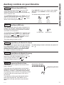
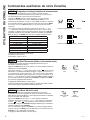
MODE 5
Temperature Limiting
7HPSHUDWXUHOLPLWLQJLVDIHDWXUHWKDWUHGXFHVHQHUJ\
costs by limiting the lowest temperature that can be
obtained in cooling and the highest temperature that can
be obtained in heating.
Press MODE until a 5 appears in the first digit of the
display for Temperature LimitingFRROPRGH7KH
COOL/('OLJKWRQWKHPDLQFRQWUROZLOOEHOLW7R
change to heat mode, press MODE again and the HEAT
/('OLJKWRQWKHPDLQFRQWUROZLOOEHOLW
7RVHWWKHWHPSHUDWXUHOLPLWVSUHVVWKHRUSDG
7KHVHFRQGGLJLWRIWKHGLVSOD\ZLOOEHEHWZHHQDQG
GHSHQGLQJRQWKHOLPLW\RXZDQWWRVHW7KHFKDUWVKRZV
the limits available. Press AUX SET to lock in your
VHOHFWLRQDQGH[LWAUX SET mode, or press MODE to
continue setting other functions.
MODE 6
Use Wall Thermostat
Setting this mode to ON will allow the unit to operate
ZLWKD&ODVV5HPRWH&RQWURO:DOO7KHUPRVWDW
Press MODE until a 6 appears in the first digit of the
display for Class 2 mode.
7KHGHIDXOWVHWWLQJIRU0RGHLV2))
Press the + pad to turn the option ON “ ´IRU
³VWDQGDUGFRROKHDW´WKHUPRVWDWV3UHVVWKH+ pad
again to turn the option ON “ “ for “auto change
RYHU´WKHUPRVWDW<RXPD\SUHVVWKHSDGWRUHWXUQ
to the previous setting. Press AUX SET to lock in your
VHOHFWLRQDQGH[LWAUX SET mode, or press MODE to
continue setting other functions.
:KHQWKLVPRGHLVDFWLYHWKHGLVSOD\ZLOOVKRZ³8VH
:DOO7KHUPRVWDW´ZKHQDQ\NH\LVSUHVVHG
MODE 7
Duct Mode
7KLVVHWWLQJLVXVHGZKHQWKHXQLWLVLQVWDOOHGZLWKDGXFW
DGDSWHUNLW,IWKHXQLWLVGXFWHGWKH'XFW0RGHQHHGV
WREHVHWWR217KLVLQFUHDVHVWKHIDQVSHHGWRHQVXUH
proper circulation.
Press MODE until a 7 appears in the first digit of the
display. Press the + or - pad to set this switch to
OFF “ “ or ON “ ´7KLVLVVKRZQLQWKHVHFRQGGLJLW
of the display. Press AUX SET to lock in your selection
DQGH[LWAUX SET mode.
)RU0RGHO$=SUHVVMODE to continue setting other
functions. Pressing MODE RQ0RGHO$=ZLOOUHWXUQ
you to AUX SETPRGHDQGDQ³$8´ZLOODSSHDULQWKH
display.
7KHGHIDXOWVHWWLQJIRU0RGHLV2))
7HPSHUDWXUHOLPLWV²&RRO 7HPSHUDWXUHOLPLWV²+HDW
)WR) )WR)
)WR) )WR)
)WR) )WR)
)WR) )WR)
)WR) )WR)
)WR) )WR)
)WR) )WR)
)WR) )WR)
7KHGHIDXOWVHWWLQJIRU0RGHLVDV
IROORZV
&RRO)WR)
+HDW)WR)
7HPSHUDWXUH/LPLWLQJ&RRO±/LPLW
2
7HPSHUDWXUH/LPLWLQJ+HDW±/LPLW
5
Duct Mode
OFF
Duct Mode ON
Class 2 OFF
Class 2 ON
&RRO+HDW
Class ON
$XWR&KDQJH2YHU

49-7774-2
Auxiliary controls on your Zoneline
USING THE ZONELINE
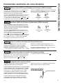
MODE 8
All-Electric Heat (AZ65 only)
7KLVHOHFWULFKHDWRSWLRQIXQFWLRQVRQO\RQWKH$=
model. When this option is ON “
´KHDWSXPS
operation is locked out, causing the unit to provide only
electric resistance heat.
7RVHWAll-Electric Heat option, press MODE until an 8
appears in the first digit of the display. Press the + or -
pad to set this switch to OFF “
“ or ON “ ´7KLVLV
shown in the second digit of the display.
Press AUX SETWRORFNLQ\RXUVHOHFWLRQDQGH[LWAUX
SET mode, or press MODE to continue setting other
functions.
7KHGHIDXOWVHWWLQJIRU0RGHLV2))
MODE 9
Heat Boost (AZ65 only)
When Heat Boost is ON and outside temperatures are
EHWZHHQ)DQG)VXSSOHPHQWDU\HOHFWULFKHDWWR
the heat pump operation to help maintain a consistent,
comfortable room temperature.
7RVHW+HDW%RRVWSUHVVMODE until a 9 appears in the
first digit of the display. Press the + or - pad to set this
switch to OFF “ “ or ON “ ´7KLVLVVKRZQLQWKH
second digit of the display. Press AUX SET to lock in
\RXUVHOHFWLRQDQGH[LWAUX SET mode.
7KHGHIDXOWVHWWLQJIRU0RGHLV2))
All-
Electric
Heat OFF
All-
Electric
Heat ON
Heat Boost OFF
Heat Boost ON
MODE 0
Digital Makeup Air Module Fan Speed
Press MODE XQWLODDSSHDUVLQWKHILUVWGLJLWRIWKHGLVSOD\
IRUWKH'LJLWDO0DNHXS$LUPRGH7RWXUQRIIWKHPRGXOHRU
FKDQJHWKHIDQVSHHGVSUHVVWKHRUSDGLQGLFDWHV
WKHPRGXOHLVRII PRGXOHRQZLWKIDQVVHWDWFIP
PRGXOHRQZLWKIDQVVHWDWFIPHWF
7KHGHIDXOWVHWWLQJIRU0RGHLV21ZLWKDIDQVSHHGRI
cfm “ “
MODE E
Digital Makeup Air Module Occupancy
7RHQDEOHRFFXSDQF\GHWHFWLRQSUHVV02'(XQWLODQ(
appears in the first digit of the display. Press the + or - pad
to set occupancy detection to OFF “ ´RU21³ ´
7KHGHIDXOWVHWWLQJIRU0RGH(LV2))³ ´
MODE P
Engineering Revision Setup
7KLVVHWWLQJLVXVHGWRFRQILJXUHWKHXQLWZKHQWKHFLUFXLW
board is replaced.
7KHILUVWWLPHWKHXQLWLVSRZHUHGDIWHUDVHUYLFHERDUGLV
LQVWDOOHGWKHXQLWZLOODXWRPDWLFDOO\HQWHUWKLVPRGH7KH8,
ZLOOUHDG³3´3UHVVWKH³´SDGXQWLOWKHQXPEHUPDWFKHV
WKHHQJLQHHULQJUHYLVLRQDVVKRZQ7KHHQJLQHHULQJUHYLVLRQ
LVWKHODVWQXPEHULQWKHPRGHOQXPEHU3UHVV³$X[´WR
VDYHDQGH[LW
7KHHQJLQHHULQJUHYLVLRQPD\EHDGMXVWHGDIWHUWKHILUVW
SRZHUF\FOHXVLQJ$8;6(73UHVV02'(XQWLO³3´
appears in the first digit, and follow the steps described
above.
Nomenclature Example
AZ45E09DABW2
Engineering Revision

49-7774-2
Auxiliary controls on your Zoneline
USING THE ZONELINE
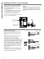
Auxiliary Controls - Terminal Connections
7KHDX[LOLDU\FRQWUROWHUPLQDOFRQQHFWVDUHORFDWHG
behind the room cover beneath the access cover.
7XUQRIIDQGXQSOXJWKHXQLW
5HPRYHWKHURRPFRYHU6HHWKH7R5HPRYHWKH
Room Cover section.
7RPDNHZLULQJFRQQHFWLRQVLQVHUWWKHFRQQHFWRUV
LQWRWKHDSSURSULDWHWHUPLQDOVRQWKHFRQWUROER[
$IWHUDOOGHVLUHGFRQQHFWLRQVKDYHEHHQPDGH
replace the access cover and room cover.
7KHRZQHULVUHVSRQVLEOHIRUPDNLQJDOOFRQQHFWLRQVDQG
setting the appropriate AUX SET mode.
NOTICE:
,PSURSHUZLULQJPD\GDPDJHWKH=RQHOLQHHOHFWURQLFV
No common busing is permitted. Damage or erratic
operation may result. A separate wire pair must be run
from each separate controlling switch to each individual
=RQHOLQH
Red
$X[6HW
Button
:KHQFRQQHFWHGDQDX[LOLDU\RUH[WHUQDOIDQFDQEH
FRQWUROOHGZLWKWKHLQGRRUIDQPRWRURQWKH=RQHOLQH
&RQQHFWLRQVSURYLGH9$&WRHQHUJL]HDUHPRWH
relay.
7RHQDEOHWKLVIHDWXUHD:3;FRQWUROERDUG
and a RAKCDC accessory must be installed.
External Fan (Field Installed)
7KH&HQWUDO'HVN&RQWUROLVDIHDWXUHWKDWDOORZVWKHXQLW
WREHPDGHRSHUDEOHLQRSHUDEOHIURPDUHPRWHORFDWLRQ
Operation of the feature requires that an ON-OFF switch
at the remote location be wired to the two CDC terminals
RQWKHFRQWUROSDQHORIWKH=RQHOLQH:KHQWKHUHPRWH
VZLWFKLV&/26('WKHXQLWFDQQRWEHRSHUDWHGLQWKH
)DQ&RRORU+HDWPRGHVE\WKHFRQWURO7KH)UHH]H
Sentinel and the Heat Sentinel features remain operable.
When the remote switch is Open, the unit is fully
operable by control.
7KH5$.&'&DFFHVVRU\PXVWEHXVHGZLWKDFHQWUDO
GHVNFRQWUROV\VWHP1R³&RPPRQ%XVLQJ´LVSHUPLWWHG
,WVKRXOGEHQRWHGWKDW&'&FDQQRWEHXVHGRQ'%0DQG
EBM models when occupancy is enabled.
Central Desk Control (Field Supplied)*
CDC Switch
CDC
CDC
R
R
E. Fan
E. Fan
&RQQHFWWRH[WHU-
nal fan relay
&RQQHFWWRH[WHUQDO
fan relay
CDC Switch
CDC
R
E. Fan
12
3
R
CDC
Ext Fan
RedCDC
Ext Fan
([WHUQDO)DQ&'&
Connector Socket
5HPRWH7KHUPRVWDW
Connector Socket

49-7774-2
Auxiliary controls on your Zoneline
USING THE ZONELINE
7KH5HPRWH7KHUPRVWDW&RQQHFWRUVDUHLQFOXGHGZLWK
HDFK=RQHOLQH
When connected to a remote thermostat, the indoor
air temperature sensing is shifted from the unit to
the remote thermostat. For this reason, the units will
operate slightly differently when connected to a remote
WKHUPRVWDW7KHIROORZLQJFKDUWVKRZVWKHXQLWRSHUDWLRQ
when connected to a remote thermostat.
IMPORTANT: 7KH=RQHOLQHWKHUPRVWDWFRQQHFWLRQV
SURYLGH9$&RQO\
,IXVLQJDGLJLWDOHOHFWURQLFZDOOWKHUPRVWDW\RXPXVWVHW
LWWRWKH9$&VHWWLQJ6HHWKH,QVWDOODWLRQ,QVWUXFWLRQV
for the wall thermostat.
NOTICE:
'DPDJHWRDZDOOWKHUPRVWDWRUWRWKH=RQHOLQH
electronics can result from improper connections.
Special care must be used in connecting the wires. No
line voltage connections should be made to any circuit.
,VRODWHDOOZLUHVLQEXLOGLQJIURPOLQHYROWDJH
Remote Thermostat
Feature Heat Pump Electric Heat
,QGRRU)URVW&RQWURO Yes Yes
Freeze Sentinel Yes Yes
(OHFWURQLF7HPSHUDWXUH/LPLWLQJ No No
Switch to Resistance Heat Based
RQ,QGRRU7HPSHUDWXUH
'HWHUPLQHGE\5HPRWH7KHUPRVWDW 1$
Switch to Resistance Heat Based
RQ2XWGRRU7HPSHUDWXUH
Yes 1$
Reverse Cycle Defrost Yes 1$
Simultaneous Partial Resistance Heat with
Heat Pump
Yes 1$
5HVLVWDQFH+HDW/RFNRXW Yes 1$
³6PDUW)DQ´)DQ&\FOH )DQ21$8726HW2Q5HPRWH7KHUPR-
stat
)DQ2Q$XWR6HW2Q
5HPRWH7KHUPRVWDW
Central Desk Control Yes Yes
NOTE: 7KH&ODVV0RGHVHWWLQJ0RGHPXVWEHVHWWR21³ “ for the unit to operate with a Class 2 Remote Wall
7KHUPRVWDW6HHWKHLQVWDOODWLRQLQVWUXFWLRQVVXSSOLHGZLWKWKHUHPRWHWKHUPRVWDWDQGPRGHLQVWUXFWLRQVRQSDJH
123456
7
C
W
YB
GH
GL
R
yellow
black
whit
e
blue
green
tan
red

49-7774-2
USING THE ZONELINE
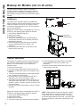
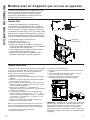
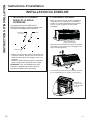
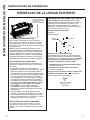
Makeup Air Models (not on all units)
7KHPDNHXSDLUYHQWLODWLRQV\VWHPLVGHVLJQHGWR
provide continuous outdoor air through the vent door
DQGLQWRWKHURRP,QDGGLWLRQWRSURYLGLQJIUHVKDLULW
dehumidifies incoming air when it is above 55% relative
humidity.
7KHPDNHXSDLUYHQWLODWLRQV\VWHPLVRSHUDWHGE\D
switch located on the front of the electrical control cover
XQGHUWKH=RQHOLQHURRPIURQW7KHV\VWHPLVWXUQHG
RQDQGRIIE\GHSUHVVLQJWKHRQ,RURII2EXWWRQDV
shown in the illustration.
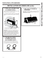
6KRXOGWKH=RQHOLQHQHHGWREHRSHUDWHGDVD37$&RU
37+3RQO\WKHIROORZLQJVWHSVVKRXOGEHIROORZHG
2UGHUVHUYLFH31:3;
8QSOXJWKH=RQHOLQH
3. Remove the room front.
7XUQRIIWKHYHQWLODWLRQV\VWHPE\GHSUHVVLQJWKH
RQRIIEXWWRQVRWKDWRII2LVVHOHFWHGVHHDERYH
LOOXVWUDWLRQIRUORFDWLRQ
3XOOWKH=RQHOLQHIURPWKHZDOOVOHHYHDQGLQVWDOO
VHUYLFH31:3;DVVKRZQLQWKH
illustration.
3XVKWKH=RQHOLQHEDFNLQWRWKHZDOOVOHHYHDQG
restore power to the unit.
*DAM Models
Service PN
:3;
2Q2II
7KHPDNHXSDLUYHQWLODWLRQV\VWHPLVRSHUDWHGWKURXJK
WKH=RQHOLQH¶VDX[LOLDU\PHQXVHH$X[LOLDU\&RQWUROV
VHFWLRQ7RWXUQWKHV\VWHPRQRURIIIROORZWKH
GLUHFWLRQVEHORZ
5HPRYHWKHURRPIURQW
2. Press the mode control button and turn off the unit
3UHVVWKHUHG$8;6(7EXWWRQ³$8´DSSHDUVRQWKH
GLVSOD\
7RWXUQRIIWKH08$0SUHVVWKHPRGHFRQWUROEXWWRQ
XQWLO³´DSSHDUVLQWKHILUVWGLJLW
3UHVVWKHPLQXVRQWKHFRQWUROSDQHOXQWLO³´LV
displayed to turn off the makeup air module.
7KHV\VWHPLVSUHVHWIURPWKHIDFWRU\DWFIP7R
change that value press the + or - for the fan speed
GHVLUHG FIP FIP FIP FIP
FIPDQG FIP
'HSUHVVWKHUHG$X[EXWWRQDJDLQWRUHWXUQWRQRUPDO
operation.
6KRXOGWKH=RQHOLQHQHHGWREHRSHUDWHGDVD37$&RU
37+3RQO\WKHIROORZLQJVWHSVVKRXOGEHIROORZHG
2UGHUVHUYLFH31:3;
8QSOXJWKH=RQHOLQH
3. Remove the room front.
7XUQRIIWKHPDNHXSDLUPRGXOHDVLQVWUXFWHGDERYH
3XOOWKH=RQHOLQHIURPWKHZDOOVOHHYHDQGLQVWDOO
VHUYLFH31:3;DVVKRZQLQWKH
illustration.
3XVKWKH=RQHOLQHEDFNLQWRWKHZDOOVOHHYHDQG
restore power to the unit.
NOTE: Digital makeup air units will perform a system
check upon power up, power cycle and once every
GD\VLIWKHXQLWLVLQRFFXSDQF\PRGH7KHV\VWHP
FKHFNODVWVDSSUR[LPDWHO\VHFRQGV'XULQJWKLVWLPH
the fans will speed up, slow down, and then go to the
set point.
*DBM and *EBM Models

49-7774-2
Care and Cleaning
CARE AND CLEANING
7XUQWKH=RQHOLQHRIIDQGGLVFRQQHFWWKHSRZHUVXSSO\ 7RFOHDQXVHZDWHUDQGDPLOGGHWHUJHQW
Do not use bleach or abrasives. Some commercial
cleaners may damage the plastic parts.
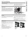
Room Cover and Case
7KHFRLOVRQWKHRXWGRRUVLGHRIWKH=RQHOLQHVKRXOGEH
FKHFNHGUHJXODUO\,IWKH\DUHFORJJHGZLWKGLUWRUVRRW
they should be cleaned by either low or no pressure
FOHDQLQJPHWKRGV(QVXUHWKDWHOHFWULFDODUHDGHYLFHV
are protected during cleaning. You will need to remove
WKHXQLWIURPWKHZDOOVOHHYHWRLQVSHFWWKHFRLOV7KHGLUW
buildup occurs on the fan side of the outdoor coil.
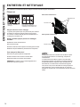
Outdoor Coils
Coils
Grille
Clean the outside coils regularly.
,QVRPHLQVWDOODWLRQVGLUWRURWKHUGHEULVPD\EHEORZQ
into the unit from the outside and settle in the base pan
WKHERWWRPRIWKHXQLW
,QVRPHDUHDVRIWKH8QLWHG6WDWHVDQDWXUDOO\RFFXUULQJ
³JHOOLNH´RU³VOLPHOLNH´VXEVWDQFHPD\EHVHHQLQWKH
base pan.
Check it periodically and clean, if necessary.
2Q6HULHVPRGHOVGRQRWUHPRYHWKHUXEEHUGUDLQ
SOXJIURPWKHEDVHSDQ,IUHPRYHGH[FHVVZDWHUPD\
drain to the outside.
Base Pan
,IWKHYHQWGRRULVRSHQFOHDQWKHYHQWILOWHUWZLFHD\HDU
or as required. Access requires the removal of the unit
from the wall sleeve.
7XUQWKH=RQHOLQHRIIDQGXQSOXJEHIRUHUHPRYLQJDQG
cleaning.
To clean the vent filter:
IMPORTANT: 7KLVILOWHULVQRWUHPRYDEOH7U\LQJWR
remove this filter will damage the unit.
Ŷ8VHDYDFXXPWRUHPRYHGHEULVIURPWKHILOWHU
Ŷ8VHDGDPSUDJWRZLSHGRZQWKHILOWHUDQG
surrounding area after vacuuming.
Ventilation Filter
Remove
the shipping
screws
(if operation is
GHVLUHG

49-7774-2
CARE AND CLEANING
Care and Cleaning
Turn the Zoneline off before cleaning.
7KHPRVWLPSRUWDQWWKLQJ\RXFDQGRWRPDLQWDLQWKH
=RQHOLQHLVWRFOHDQWKHILOWHUDWOHDVWHYHU\GD\V
Clogged filters reduce cooling, heating and air flow.
Keeping these filters clean will:
Ŷ'HFUHDVHFRVWRIRSHUDWLRQ
Ŷ6DYHHQHUJ\
Ŷ3UHYHQWFORJJHGKHDWH[FKDQJHUFRLOV
Ŷ5HGXFHWKHULVNRISUHPDWXUHFRPSRQHQWIDLOXUH
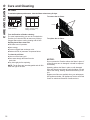
To clean the air filters:
Ŷ9DFXXPRIIWKHKHDY\VRLO
Ŷ5XQZDWHUWKURXJKWKHILOWHUVIURPWKH
back side.
Ŷ'U\WKRURXJKO\EHIRUHUHSODFLQJ
NOTE: 7KHDLUILOWHUVDUHLQWHUFKDQJHDEOHDQGZLOOILWLQ
either the right or left side.
To remove the air filters:
To replace the air filters:
NOTICE:
'RQRWRSHUDWHWKH=RQHOLQHZLWKRXWWKHILOWHUVLQSODFH,I
a filter becomes torn or damaged, it should be replaced
immediately.
Operating without the filters in place or with damaged
filters will allow dirt and dust to reach the indoor coil and
reduce the cooling, heating, airflow and efficiency of the
unit.
Replacement filters are available from your salesperson,
GE Appliances dealer, GE Appliances Service and Parts
Center or authorized Customer Care® servicers.
To maintain optimum performance, clean the filters at least every 30 days.
Air Filters
FRONT
FRONT
Dirty filter—
Needs cleaning
Clogged filter—
Greatly reduces cooling,
heating and airflow.
Pull up
Push down

49-7774-2
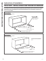
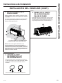
Installation Instructions
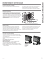
INSTALLATION INSTRUCTIONS
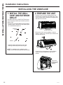
BEFORE YOU BEGIN
Read these instructions completely and carefully.
•
IMPORTANT – Save these
instructions for local inspector’s use.
•
IMPORTANT – Observe all
governing codes and ordinances.
• Note to Installer – Be sure to leave these
instructions with the owner.
• Note to Owner – Keep these instructions for
future reference.
• Proper installation is the responsibility of the
installer.
• Product failure due to improper installation is not
covered under the Warranty.
• You must use all supplied parts and use proper
installation procedures as described in these
instructions when installing this air conditioner.
Questions? Call 844-GE4-PTAC (or 844-434-7822 ) or Visit our Website at: GEAppliances.com
Phillips screwdriver
RU´1XWGULYHU
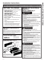
TOOLS YOU WILL NEED
NOTE – As with any mechanical device with moving
SDUWVWKLVXQLWZLOOKDYHDZHDULQSHULRG$)7(5
,167$//$7,21WKLVXQLWVKRXOGEHRSHUDWHGIRU
hours to achieve optimum efficiency.
AIR CONDITIONER BREAK-IN
PERIOD
ZONELINE COMPONENTS
Appearance may vary.
*6KLSSHGZLWKWKH=RQHOLQHXQLW
&KHFNWKH³(VVHQWLDO(OHPHQWV´OLVW
on the unit located on front of the
base pan
([WHULRUJULOOHORXYHU
Wall case**
=RQHOLQHXQLW
Room
cover*
Power
supply kit**
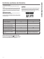
IMPORTANT ELECTRICAL
SAFETY—
READ CAREFULLY
• Follow the National Electrical Code (NEC) or local codes
and ordinances.
• For personal safety, this Zoneline must be properly
grounded.
• Protective devices (fuses or circuit breakers) acceptable
for Zoneline installations are specified on the nameplate
of each unit.
• Do not use an extension cord with this unit.
• Aluminum building wiring may present special
problems—consult a qualified electrician.
• When the unit is in the OFF position, there is still voltage
to the electrical controls.
• Disconnect the power to the unit before servicing by:
1 Removing the power cord (if it has one) from the wall
receptacle. OR
2 Removing the branch circuit fuses or turning the
circuit breakers off at the panel.
• Suivez le Code national de l’électricité (CNE) ou vos
ordonnances et codes locaux.
• Pour votre sécurité personnelle, ce Zoneline doit être bien mis à la
terre.
• Les appareils protecteurs (fusibles ou disjoncteurs) acceptables
pour installer votre Zoneline sont indiqués sur la plaque signalé-
tique de chaque appar eil.
• N’utilisez jamais de rallonge électrique avec cet appareil.
/HV¿OVGHEkWLPHQWHQDOXPLQLXPSHXYHQWSRVHUGHVSUREOqPHV
SDUWLFXOLHUV²FRQVXOWH]XQpOHFWULFLHQTXDOL¿p
• Quand votre appareil est en position OFF (arrêt), il reste de la ten-
sion dans les commandes électriques.
• Débranchez le courant de votre appareil avant de l’entretenir ou
de le réparer en:
1. Enlevant le cordon d’alimentation (le cas échéant) de la prise
murale. OU
2. Enlevant les fusibles du circuit de dérivation ou en débran-
chant les disjoncteurs de dérivation au panneau.
• Siga las instrucciones del National Electrical Code (Código de
Electricidad Nacional) (NEC) o los códigos u ordenanzas locales.
•Para su seguridad personal, el acondicionador de aire Zoneline
debe tener una adecuada conexión a tierra.
• Los dispositivos de protección (fusibles o disyuntores) adecua-
GRVSDUDODVLQVWDODFLRQHVGH=RQHOLQHVHHQFXHQWUDQHVSHFL¿FD-
dos en la placa de cada unidad.
• No utilice un cable de extensión con esta unidad.
• El cableado de aluminio puede presentar problemas especiales:
FRQVXOWHDXQHOHFWULFLVWDFDOL¿FDGR
• Cuando la unidad se encuentra en la posición OFF (apagado),
todavía hay voltaje en los controles eléctricos.
• Antes de realizar reparaciones en la unidad, desconecte el sumi-
nistro de energía de la siguiente manera:
1 Retire el cable eléctrico (si posee uno) del receptáculo de la
pared. O
2 Retire los fusibles de la sección o apague el disyuntor desde el
panel.
CAUTION
ATTENTION
PRECAUCIÓN

49-7774-2
Installation Instructions
INSTALLATION INSTRUCTIONS
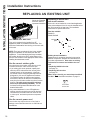
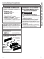
Use the correct wall case
7KLVXQLWis designed to be installed in a GE
$SSOLDQFHVSODVWLFRULQVXODWHGPHWDOZDOOFDVH7KLV
minimizes condensation from forming on the room side
of the case.
NOTE: 7KHUHDUHVHYHUDOH[WUDKROHVLQWKHXQLWVLGH
flanges for installation in wall cases other than GE
$SSOLDQFHV7RDYRLGGDPDJLQJWKHIODQJHLQVXODWLRQ
the installer should use an awl or other sharp tool to
puncture the insulation in the appropriate holes before
installing the attachment screws.
Use the correct outdoor grille
You should use the outdoor grilles shown on the
³(VVHQWLDO(OHPHQWV´ODEHORQWKHEDVHSDQ
•,IDQH[LVWLQJJULOOHLVQRWUHSODFHGFDSDFLW\DQG
efficiency will be reduced and the unit may fail to
operate properly or fail prematurely. A deflector
NLW5$.PD\EHXVHGZLWKJULOOHVWKDWZHUHQRW
GHVLJQHGIRU\RXUQHZ*($SSOLDQFHV=RQHOLQHV
7KH5$.FRQWDLQVDLUGHIOHFWRUVDQGJDVNHWV
WKDWPRXQWWRWKHXQLWWRGLUHFWWKHKRWH[KDXVWDLU
away from the air intake to allow the unit to function
properly. The grille must have a 65% minimum
free area (as calculated by ASHRAE). See the
Architects and Engineers Data Manual for more
detailed information.
• Any vertical deflectors in a non GE Appliances
H[LVWLQJUHDUJULOOHVKRXOGEHUHPRYHGWRGHFUHDVH
condenser air recirculation that can cause the unit
WR³VKRUWF\FOH´DQGOHDGWRSUHPDWXUHFRPSRQHQW
failure.
Use the correct power cord
/RFDOFRGHVPD\UHTXLUHWKHXVHRIDUFIDXOWRU
OHDNDJHFXUUHQWGHWHFWLRQGHYLFHVRQYROW
installations.
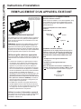
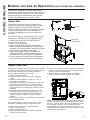
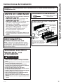
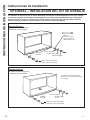
Replacing a ducted unit
New ducted installation:
,IWKLVXQLWLVWREHLQVWDOOHGLQDQHZGXFWHGDSSOLFDWLRQ
using a duct adapter kit, the kit must be installed before
WKHXQLWLVSODFHGLQWKHZDOOFDVH7KHLQVWDOODWLRQ
instructions are packed with the kit.
Duct kits available:
5$.
5$.%%
Existing ducted installation:
5HSODFHPHQWRIDQH[LVWLQJGXFWHGXQLWPD\UHTXLUH
different components. Request this information from
your sales representative. Duct seals on existing
unit need to be removed and added to the new
unit.
• Replacing 230/208 volt units:
6HHSDJH
• Replacing 265 volt units:
6HHSDJH
When using a duct kit, you must always turn Mode
7 to ON “ ”6HH0RGHLQVWUXFWLRQVRQSDJH
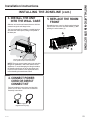
REPLACING AN EXISTING UNIT
Check the “Essential
(OHPHQWV´ODEHOIRU
important information.
Duct
Case
Mounting
plate
Duct Mode
Shown ON

49-7774-2
Installation Instructions
INSTALLATION INSTRUCTIONS
ELECTRICAL SUBBASE
CONNECTION
Power cords may include an arc fault
interruption or a leakage current detection
interruption device. A test and reset button is
provided on the plug case or the inline case.
The device should be tested on a periodic basis
by first pressing the TEST button and then the
RESET button. If the TEST button does not trip
or if the RESET button will not stay engaged,
discontinue use of the Zoneline and contact a
qualified service technician.
'HSHQGLQJRQDSSOLFDWLRQDSRZHUVXSSO\NLWZLWK/&',
PXVWEHXVHGWRVXSSO\SRZHUWRWKH=RQHOLQHXQLW7KH
appropriate kit is determined by the voltage, the means
of electrical connection and the amperage of the
branch circuit.
&RQQHFWLRQVRIRUYROWFLUFXLWVPD\EHZLWKD
SRZHUVXSSO\NLWRUDMXQFWLRQER[NLW
All wiring, including installation of the receptacle,
must be in accordance with the NEC and local
codes, ordinances and regulations. Codes require
the use of an arc fault or leakage current detection
GHYLFHRQWKHSRZHUFRUGH[FHSWGLUHFWFRQQHFW%H
sure to select the correct cord for your installation.
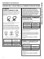
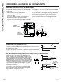
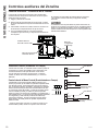
230/208 VOLT ELECTRICAL CONNECTION OPTIONS
POWER
CORD CONNECTION
DIRECT CONNECTION
2UGHUWKHIROORZLQJ.LWIRUYROWGLUHFW
FRQQHFWLRQDVUHTXLUHG
Review installation instructions provided with power
cord or direct connect kits for detailed assembly
instructions.
,IXVLQJDVXEEDVHFRQQHFWLRQWKH5$.&
-XQFWLRQ%R[LVDOVRQHFHVVDU\IRUDFRPSOHWH
installation.
Tandem
$PS
YROWUHFHSWDFOHFRQILJXUDWLRQ
Perpendicular
$PS
Large
Tandem
$PS
Power supply kit
(Appearance may vary)
YROWPRGHOVPD\EHLQVWDOOHGXVLQJRQHRI
WKHIROORZLQJHOHFWULFDOVXEEDVHV
Electrical subbases provide an enclosure for direct
FRQQHFWLRQRUHQFORVHGUHFHSWDFOHV7KHVXEEDVHNLW
includes the power cord.
7KHLQVWUXFWLRQVSURYLGHGZLWKWKHVHOHFWHGVXEEDVH
NLWPXVWEHFDUHIXOO\IROORZHG,WLVWKHUHVSRQVLELOLW\RI
the installer to ensure the connection of components
is done in accordance with these instructions and all
electrical codes.
,IXVLQJDVXEEDVHFRQQHFWLRQWKH5$.&
-XQFWLRQ%R[LVDOVRQHFHVVDU\IRUDFRPSOHWH
installation.
Branch Circuit and
Unit Amperage Rating
Proper GE Appliances
Power Cord
with LCDI Device
5$.3
5$.3
5$.3
Branch Circuit and
Unit Amperage Rating
Proper GE Appliances
Subbase Kit
5$.'3$
5$.'3$
5$.'3$
Branch Circuit and
Unit Amperage Rating
Power Supply Kit
5$.'
5$.'
5$.'

49-7774-2
Installation Instructions
INSTALLATION INSTRUCTIONS
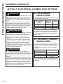
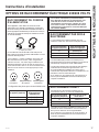
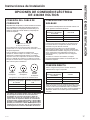
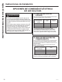
265 VOLT ELECTRICAL CONNECTION OPTIONS
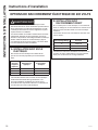
&RQQHFWLRQRIWKLV9$&SURGXFWWRDEUDQFKFLUFXLW
MUST be done by direct connection in accordance with
the National Electrical Code. Plugging this unit into a
EXLOGLQJPRXQWHGH[SRVHGUHFHSWDFOHLVQRW permitted by
code.
7KHVHPRGHOVPXVWEHLQVWDOOHGXVLQJWKHDSSURSULDWH
GE Appliances power supply kit for the branch circuit
amperage and the electrical resistance heater wattage
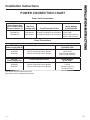
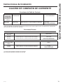
GHVLUHG8VHWKH32:(5&211(&7,21&+$57RQ
SDJHWRGHWHUPLQHWKHFRUUHFWNLWUHTXLUHG2QHRIWKH
IROORZLQJLQVWDOODWLRQPHWKRGVPXVWEHXVHG
9RXV'(9(=EUDQFKHUFHSURGXLWDOLPHQWpSDUFRXUUDQW
DOWHUQDWLIGHYROWVDXFLUFXLWGHGpULYDWLRQSDU
EUDQFKHPHQWGLUHFWFRQIRUPpPHQWDX&RGHQDWLRQDO
G¶pOHFWULFLWp/H&RGHQ¶DXWRULVHSDVOHEUDQFKHPHQ
WGHYRWUHDSSDUHLOjXQHSULVHH[SRVpHPRQWpHVXUOH
bâtiment.
9RXVGHYH]LQVWDOOHUFHVPRGqOHVjO¶DLGHGHODERQQH
WURXVVHG¶DOLPHQWDWLRQpOHFWULTXH*($SSOLDQFHVSRXU
O¶DPSpUDJHGXFLUFXLWGHGpULYDWLRQHWODSXLVVDQFHGX
FKDXႇDJHjUpVLVWDQFHpOHFWULTXHGpVLUpH8WLOLVH]OH
7DEOHDXGHFRQWDFWpOHFWULTXHSDJHSRXUGpWHUPLQHU
ODERQQHWURXVVHUHTXLVH9RXVGHYH]XWLOLVHUO¶XQHGHV
PpWKRGHVVXLYDQWHVG¶LQVWDOODWLRQ
/DFRQH[LyQGHHVWHSURGXFWRGHYROWLRVGH&$
a un circuito derivado DEBE realizarse mediante una
FRQH[LyQGLUHFWDGHDFXHUGRDODVLQGLFDFLRQHVGHO1(&
(OFyGLJRQRSHUPLWHHQFKXIDUHVWDXQLGDGDXQDFDMD
H[WHUQD
Estos modelos deben instalarse utilizando el kit de GE
Appliances de suministro de energía adecuado para el
DPSHUDMHGHFLUFXLWRGHULYDGR\HOYDWLDMHGHVHDGRSDUD
HOFDOHIDFWRUGHUHVLVWHQFLDHOpFWULFD8WLOLFHOD7$%/$
'(&21(;,21(6(/e&75,&$6HQODSiJLQDSDUD
determinar cuál es el kit necesario. Debe utilizarse uno
GHORVVLJXLHQWHVPpWRGRVGHLQVWDODFLyQ
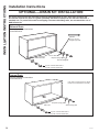
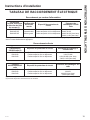
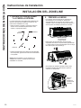
A. FOR SUBBASE
INSTALLATION
(OHFWULFDOVXEEDVHNLWVDUHDYDLODEOHWRSURYLGHDIOH[LEOH
enclosure for direct connection.
7KHLQVWUXFWLRQVSURYLGHGZLWKWKHVHOHFWHGVXEEDVH
NLWPXVWEHFDUHIXOO\IROORZHG,WLVWKHUHVSRQVLELOLW\RI
the installer to ensure the connection of components
is done in accordance with these instructions and all
electrical codes.
B. FOR DIRECT CONNECT
INSTALLATION
,IDQHOHFWULFDOVXEEDVHLVQRWXVHGGLUHFWFRQQHFWLRQ
WREUDQFKFLUFXLWZLULQJLQVLGHWKHSURYLGHGMXQFWLRQER[
must be done in accordance with the following steps.
Order the following Kit for 265-volt direct connection
DVUHTXLUHG
Review installation instructions provided with power
cord or direct connect kits for detailed assembly
instructions.
WARNING
AVERTISSEMENT
ADVERTENCIA
Branch Circuit and
Unit Amperage Rating
Power Supply Kit
5$.'
5$.'
5$.'
Branch Circuit and
Unit Amperage
Rating
Proper GE
Appliances
Subbase Kit
Power
Supply Kit
5$.( 5$.3
5$.( 5$.3
5$.( 5$.3
La page est en cours de chargement...
La page est en cours de chargement...
La page est en cours de chargement...
La page est en cours de chargement...
La page est en cours de chargement...
La page est en cours de chargement...
La page est en cours de chargement...
La page est en cours de chargement...
La page est en cours de chargement...
La page est en cours de chargement...
La page est en cours de chargement...
La page est en cours de chargement...
La page est en cours de chargement...
La page est en cours de chargement...
La page est en cours de chargement...
La page est en cours de chargement...
La page est en cours de chargement...
La page est en cours de chargement...
La page est en cours de chargement...
La page est en cours de chargement...
La page est en cours de chargement...
La page est en cours de chargement...
La page est en cours de chargement...
La page est en cours de chargement...
La page est en cours de chargement...
La page est en cours de chargement...
La page est en cours de chargement...
La page est en cours de chargement...
La page est en cours de chargement...
La page est en cours de chargement...
La page est en cours de chargement...
La page est en cours de chargement...
La page est en cours de chargement...
La page est en cours de chargement...
La page est en cours de chargement...
La page est en cours de chargement...
La page est en cours de chargement...
La page est en cours de chargement...
La page est en cours de chargement...
La page est en cours de chargement...
La page est en cours de chargement...
La page est en cours de chargement...
La page est en cours de chargement...
La page est en cours de chargement...
La page est en cours de chargement...
La page est en cours de chargement...
La page est en cours de chargement...
La page est en cours de chargement...
La page est en cours de chargement...
La page est en cours de chargement...
La page est en cours de chargement...
La page est en cours de chargement...
La page est en cours de chargement...
La page est en cours de chargement...
La page est en cours de chargement...
La page est en cours de chargement...
La page est en cours de chargement...
La page est en cours de chargement...
La page est en cours de chargement...
La page est en cours de chargement...
La page est en cours de chargement...
La page est en cours de chargement...
La page est en cours de chargement...
La page est en cours de chargement...
La page est en cours de chargement...
La page est en cours de chargement...
La page est en cours de chargement...
La page est en cours de chargement...
La page est en cours de chargement...
La page est en cours de chargement...
-
 1
1
-
 2
2
-
 3
3
-
 4
4
-
 5
5
-
 6
6
-
 7
7
-
 8
8
-
 9
9
-
 10
10
-
 11
11
-
 12
12
-
 13
13
-
 14
14
-
 15
15
-
 16
16
-
 17
17
-
 18
18
-
 19
19
-
 20
20
-
 21
21
-
 22
22
-
 23
23
-
 24
24
-
 25
25
-
 26
26
-
 27
27
-
 28
28
-
 29
29
-
 30
30
-
 31
31
-
 32
32
-
 33
33
-
 34
34
-
 35
35
-
 36
36
-
 37
37
-
 38
38
-
 39
39
-
 40
40
-
 41
41
-
 42
42
-
 43
43
-
 44
44
-
 45
45
-
 46
46
-
 47
47
-
 48
48
-
 49
49
-
 50
50
-
 51
51
-
 52
52
-
 53
53
-
 54
54
-
 55
55
-
 56
56
-
 57
57
-
 58
58
-
 59
59
-
 60
60
-
 61
61
-
 62
62
-
 63
63
-
 64
64
-
 65
65
-
 66
66
-
 67
67
-
 68
68
-
 69
69
-
 70
70
-
 71
71
-
 72
72
-
 73
73
-
 74
74
-
 75
75
-
 76
76
-
 77
77
-
 78
78
-
 79
79
-
 80
80
-
 81
81
-
 82
82
-
 83
83
-
 84
84
-
 85
85
-
 86
86
-
 87
87
-
 88
88
-
 89
89
-
 90
90


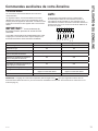
GE AZ45E07EAC Le manuel du propriétaire
- Catégorie
- Climatiseurs split-system
- Taper
- Le manuel du propriétaire
dans d''autres langues
- English: GE AZ45E07EAC Owner's manual
- español: GE AZ45E07EAC El manual del propietario
Documents connexes
-
GE AZ65H12DAC Mode d'emploi
-
GEAppliances AZ45E15DAB Le manuel du propriétaire
-
GE AZ64H15DAB Le manuel du propriétaire
-
GE AH11E09D3B Mode d'emploi
-
-
-
-
-
GE AZ95H12EAC Mode d'emploi
-
Autres documents
-
GE Profile PRV03ATTBB Le manuel du propriétaire
-
Haier 2HUM14HA03 Mode d'emploi
-
-
Moen 104638 Le manuel du propriétaire
-
Leviton M5362-R Guide d'installation
-
-
-
-
-