Dell W-Series 304/305 Access Points Guide de démarrage rapide
- Catégorie
- Points d'accès WLAN
- Taper
- Guide de démarrage rapide

Rev02 | December 2016 1
Dell Networking
300 Series Access Points
Installation Guide
The Dell Networking 300 Series wireless access points
(W-AP304, W-AP305, W-IAP304 and W-IAP305) support
IEEE 802.11ac standards for high-performance WLAN, and
are equipped with two radios, which provide network access
and monitor the network simultaneously. These access points
deliver high-performance 802.11n
2.4 GHz and 802.11ac 5 GHz functionality, while also
supporting 802.11a/b/g wireless services. Multi-user Multiple-
in, Multiple-output (MU-MIMO) is enabled when operating
in 5GHz mode for optimal performance.
The W-AP304 and W-AP305 access points work in
conjunction with a Dell controller, while the W-IAP304 and
W-IAP305 access points can be configured using a built-in
virtual controller.
The 300 Series wireless access points provide the following
capabilities:
IEEE 802.11a/b/g/n/ac operation as a wireless access point
IEEE 802.11a/b/g/n/ac operation as a wireless air monitor
IEEE 802.11a/b/g/n/ac spectrum monitor
Compatible with IEEE 802.3at PoE+ and IEEE 802.3af
PoE
Centralized management configuration and upgrade
Integrated Bluetooth Low Energy (BLE) Radio
Package Contents
300 Series access point
9/16” and 15/16” Ceiling Rail Adapters
Dell Networking 300 Series Access Points Installation
Guide (printed version)
Dell Networking 300 Series Access Points Regulatory
Compliance and Safety Information Guide
Dell Networking W-Series Instant Quick Start Guide
(W-IAP304 and W-IAP305 only)
Dell Networking W-Series Instant Access Point Professional
Installation Guide Supplement (W-IAP304 only)
.
Software
The W-AP304 and W-AP305 access points require AOS 6.5.1
or higher. For additional information, refer to the AOS User
Guide and AOS Quick Start Guide.
The W-IAP304 and W-IAP305 access points require Instant
4.3.1 or higher. For additional information, refer to the
Instant User Guide and Instant Quick Start Guide.
Hardware Overview
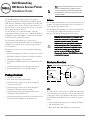
Figure 1
Status LEDs on AP Front (305 shown)
LEDs
The 300 Series access points have two LEDs that indicate the
system and radio status of the device. These two LEDs can be
configured via AOS (for W-AP304 and W-AP305) or Instant
(for W-IAP304 and W-IAP305) software for three separate
modes:
Normal mode (by default): See the following LED table.
Off mode: LEDs are off
Blink mode: Both LEDs blink green (synchronized)
Note: Inform your supplier if there are any incorrect,
missing, or damaged parts. If possible, retain the
carton, including the original packing materials. Use
these materials to repack and return the unit to the
supplier if needed.
CAUTION: Dell access points are classified as radio
transmission devices, and are subject to government
regulations of the host country. The network
administrator(s) is/are responsible for ensuring that
configuration and operation of this equipment is in
compliance with their country’s regulations. For the
complete list of country-approved channels and
devices, refer to the
Dell Networking W-Series
Downloadable Regulatory Table (DRT) Release Notes
at download.dell-pcw.com.
System Status
Radio Status

Dell Networking 300 Series Access Points | Installation Guide 2
* Blinking: 1s on/1s off
**Flashing: off a fraction of a second every 2s
External Antenna Connectors
The W-AP304 and W-IAP304 access points are equipped
with three external antenna connectors on the front corners
of the access point.
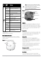
Figure 2
External Antenna Connectors
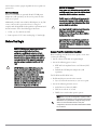
Figure 3
Back Panel
USB Port
The 300 Series is equipped with a USB port for connectivity
with cellular modems and other USB client devices. When
powered by an 802.3at PoE or DC power source, the USB port
can supply power up to 5W/1A. The USB interface is disabled
when the access point is powered by an 802.3af PoE source
(power-save mode).
Console Port
The serial console port is a 4-pin connector covered by a dust
cover. An optional serial adapter cable (AP-CBL-SER) is sold
separately to connect the device to a serial terminal or a
laptop for direct local management.
Ethernet Port
The 300 Series access points are equipped with one
10/100/1000Base-T auto-sensing MDI/MDX Ethernet port.
This port supports wired-network connectivity, in addition to
Power over Ethernet (PoE) from IEEE 802.3af and 802.3at
compliant power sources.
This device accepts 56V DC (802.3at), or 48V DC (802.3af)
nominal as a standard powered device (PD) from power
sourcing equipment, including PoE midspan injector or a
PoE-sourcing network infrastructure.
Kensington Lock Slot
The 300 Series access points are equipped with a Kensington
lock slot for additional security.
Reset Button
To reset the 300 Series access points to factory default
settings, press and hold down the reset button using a small,
LED
Color/
State
Meaning
System
Status
(Left)
Off Device powered off
Green-
Blinking*
Device booting, not ready for use
Green- Solid Device ready for use, no restrictions
Green-
Flashing
**
Device ready for use, uplink negotiated
in sub optimal speed (<1Gbps)
Amber- Solid Device ready for use; power-save mode
(802.3af PoE)
Amber-
Flashing
Device ready for use; power-save mode
(802.3af PoE), uplink negotiated in sub
optimal speed (<1Gbps)
Red- Solid System error condition
Radio
Status
(Right)
Off Device powered off, or both radios
disabled
Green- Solid Both radios enabled in access mode
Green-
Blinking
One radio enabled in access mode
Amber- Solid Both radios enabled in monitor mode
Amber-
Blinking
One radio enabled in monitor mode
Alternating One radio enabled in access mode,
other in monitor mode
ANT0 ANT1
ANT2
Note: The Equivalent Isotropically Radiated Power (EIRP)
levels for all external antenna devices must not exceed the
regulatory limit set by the host country/domain.
Installers are required to record the antenna gain for this
device in the system management software.
CONSOLE
12V 1A
Console Port
Ethernet Port
USB Port
Reset
Button
DC Power Socket
Kensington
Lock

3 Dell Networking 300 Series Access Points | Installation Guide
narrow object such as a paper clip while the access points are
powered on.
DC Power Socket
If PoE is not available, an optional AP-AC-12V30B power
adapter kit (sold separately) can be used to power the 300
Series access points.
Additionally, a locally-sourced AC-to-DC adapter (or any DC
source) can be used to power this device, as long as it
complies with all applicable local regulatory requirements and
the DC interface meets the following specifications:
12 Vdc (+/- 5%) and at least 18W
Center-positive 2.1/5.5 mm circular plug, 9.5 mm length
Before You Begin
Access Point Pre-Installation Checklist
Before installing your 300 Series access points, ensure that
you have the following:
Cat5E or better UTP cable of required length
One of the following power sources:
IEEE 802.3af-compliant Power over Ethernet (PoE)
source.
Dell AP-AC-12V30B power adapter kit (sold
separately)
For W-AP304 and W-AP305 only:
Dell Controller provisioned on the network:
Layer 2/3 network connectivity to your access point
One of the following network services:
Aruba Discovery Protocol (ADP)
DNS server with an “A” record
DHCP Server with vendor-specific options
CAUTION: FCC Statement: Improper termination of
access points installed in the United States
configured to non-US model controllers will be in
violation of the FCC grant of equipment authorization.
Any such willful or intentional violation may result in a
requirement by the FCC for immediate termination of
operation and may be subject to forfeiture (47 CFR
1.80).
ATTENTION: Déclaration FCC l’arrêt incorrect des
points d’accès installés aux États-Unis qui sont
configurés sur des contrôleurs autres que le modèle
agréé aux États-Unis est considéré comme
contrevenant à l’homologation FCC. Toute violation
délibérée ou intentionnelle de cette condition peut
entraîner une injonction d’arrêt immédiat de son
utilisation par la FCC et peut déboucher sur la
confiscation de l’équipement (47 CFR 1.80).
CAUTION: EU Statement:
Lower power radio LAN product operating in 2.4 GHz
and 5 GHz bands. Please refer to the
AOS User Guide/
Instant User Guide
for details on restrictions.
Produit réseau local radio basse puissance operant
dans la bande fréquence 2.4 GHz et 5 GHz. Merci de
vous referrer au
AOS User Guide/Instant User Guide
pour les details des restrictions.
Low Power FunkLAN Produkt, das im 2.4 GHz und im
5 GHz Band arbeitet. Weitere Informationen
bezlüglich Einschränkungen finden Sie im
AOS User
Guide/Instant User Guide.
Apparati Radio LAN a bassa Potenza, operanti a 2.4
GHz e 5 GHz. Fare riferimento alla
AOS User Guide/
Instant User Guide
per avere informazioni detagliate
sulle restrizioni.
Note: Dell access points are designed in compliance with
governmental requirements, so that only authorized network
administrators are permitted to change the settings for this
device. For more information about access point
configuration, refer to the Quick Start Guide and User Guide
for your device.

Dell Networking 300 Series Access Points | Installation Guide 4
Verifying Pre-Installation Connectivity
Before installing access points in a network environment,
make sure that they are able to locate and connect to the
controller after power on.
Specifically, you must verify the following conditions:
When connected to the network, each access point is
assigned a valid IP address
Access points are able to locate the controller
Refer to the AOS Quick Start Guide for instructions on
locating and connecting to the controller.
Pre-Installation Network Requirements
After WLAN planning is complete and the appropriate
products and their placement have been determined, the Dell
controller(s) must be installed and initial setup performed
before the Dell access points are deployed.
For initial setup of the controller, refer to the AOS Quick
Start Guide for the software version installed on your
controller.
Identifying Specific Installation
Locations
You can mount the 300 Series access point on the ceiling or a
wall. Use the access point placement map generated by Dell
VisualRF Plan software application to determine the proper
installation location(s). Each location should be as close as
possible to the center of the intended coverage area and
should be free from obstructions or obvious sources of
interference. These RF absorbers/reflectors/interference
sources will impact RF propagation and should have been
accounted for during the planning phase and adjusted for in
RF plan.
Identifying Known RF Absorbers, Reflectors and
Interference Sources
Identifying known RF absorbers, reflectors, and interference
sources while in the field during the installation phase is
critical. Make sure that these sources are taken into
consideration when you attach an access point to its fixed
location. Examples of sources that degrade RF performance
include:
Cement and brick
Objects that contain water
Metal
Microwave ovens
Wireless phones and headsets
Installing the Access Point
The 300 Series access points ship with two ceiling rail
adapters for 9/16” and 15/16” ceiling rails. Additional ceiling
rail adapters for other rail styles and wall mount adapters are
available as accessory kits.
1. Pull the necessary cables through a prepared hole in the
ceiling tile near where the access point will be placed.
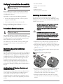
2. Place the adapter against the back of the access point with
the adapter at an angle of approximately 30 degrees to the
tabs (see Figure 4).
3. Twist the adapter clockwise until it snaps into place in the
tabs (see Figure 4).
Figure 4
Attaching the Ceiling Rail Adapter
4. Hold the access point next to the ceiling tile rail with the
ceiling tile rail mounting slots at approximately a 30-
degree angle to the ceiling tile rail (see Figure 5). Make
sure that any cable slack is above the ceiling tile.
5. Pushing toward the ceiling tile, rotate the access point
clockwise until the device clicks into place on the ceiling
tile rail.
Note: The instructions in this section are applicable to the
W-AP304 and W-AP305 only.
Note: The instructions in this section are applicable to the
W-AP304 and W-AP305 only.
CAUTION: All Dell access points should be professionally
installed by certified technician. The technician is
responsible for ensuring that grounding is available that
meets applicable regional regulatory and electrical
standards.
ATTENTION: Tous les points d'accès Dell doivent
impérativement être installés par un professionnel agréé.
Ce dernier doit s'assurer que l'appareil est mis à la terre et
que le circuit de mise à la terre est conforme aux codes
électriques nationaux en vigueur.

5 Dell Networking 300 Series Access Points | Installation Guide
Contacting Dell
Copyright
© Copyright 2016 Hewlett Packard Enterprise Development LP. Dell™,
the DELL™ logo, and PowerConnect™ are trademarks of Dell Inc.
All rights reserved. Specifications in this manual are subject to change
without notice.
Originated in the USA. All other trademarks are the property of their
respective owners.
Open Source Code
This product includes code licensed under the GNU General Public
License, the GNU Lesser General Public License, and/or certain other
open source licenses. A complete machine-readable copy of the
source code corresponding to such code is available upon request.
This offer is valid to anyone in receipt of this information and shall
expire three years following the date of the final distribution of this
product version by Hewlett-Packard Enterprise Company. To obtain
such source code, send a check or money order in the amount of US
$10.00 to:
Hewlett-Packard Enterprise Company
Attn: General Counsel
3000 Hanover Street
Palo Alto, CA 94304
USA
Website Support
Main Website dell.com
Contact Information dell.com/contactdell
Support Website dell.com /support
Documentation Website dell.com /support/manuals
Figure 5
Mounting the Access Point
Connecting Required Cables
Install cables in accordance with all applicable local and
national regulations and practices.
Verifying Post-Installation Connectivity
The integrated LEDs on the access point can be used to verify
that the access point is receiving power and initializing
successfully (see Figure 1). Refer to the Quick Start Guide for
further details on verifying post-installation network
connectivity.
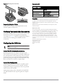
Configuring the 300 Series
Access Point Provisioning/Reprovisioning
Provisioning parameters are unique to each access point.
These local access point parameters are initially configured on
the controller which are then pushed out to the access point
and stored on the access point itself. Dell recommends that
provisioning settings be configured via the AOS Web UI only.
Refer to the AOS User Guide for complete details.
Access Point Configuration
Configuration parameters are network or controller specific
and are configured and stored on the controller. Network
configuration settings are pushed out to the access point but
remain stored on the controller.
Configuration settings can be configured via the AOS Web
UI or AOS CLI. Refer to the respective guides for complete
details.
Note: The instructions in this section are applicable to the
W-AP304 and W-AP305 only.
-
 1
1
-
 2
2
-
 3
3
-
 4
4
-
 5
5


Dell W-Series 304/305 Access Points Guide de démarrage rapide
- Catégorie
- Points d'accès WLAN
- Taper
- Guide de démarrage rapide
dans d''autres langues
Documents connexes
-
Dell W-Series 207 Access Points Le manuel du propriétaire
-
Dell W-Series 314/315 Access Points Le manuel du propriétaire
-
Dell W-Series 334/335 Access Points Le manuel du propriétaire
-
-
-
-
Dell W-Series 205H Access Points Le manuel du propriétaire
-
Dell W-Series 324/325 Access Points Le manuel du propriétaire