Sony VLP-CS6 Le manuel du propriétaire
- Catégorie
- Projecteurs de données
- Taper
- Le manuel du propriétaire

Data Projector VPL-CS6/VPL-CX6/VPL-EX1
© 2003 Sony Corporation
4-095-440-12 (1)
Data Projector
GB
FR
ES
Operating Instructions
Mode d’emploi
Manual de instrucciones
VPL-CS6
VPL-CX6
VPL-EX1

GB
2
WARNING
To prevent fire or shock hazard, do
not expose the unit to rain or
moisture.
To avoid electrical shock, do not
open the cabinet. Refer servicing to
qualified personnel only.
For the customers in the USA
If you have any questions about this product,
you may contact:
Sony Electronics Inc.
Attn: Business Information Center (BIC)
12451 Gateway Boulevard
Ft. Myers, Florida 33913
Telephone No.: 800-686-7669
The number below is for FCC related
matters only.
Declaration of Conformity
Trade Name: SONY
Model No.: VPL-CS6/VPL-CX6/VPL-EX1
Responsible Party: Sony Electronics Inc.
Address: 680 Kinderkamack Road, Oradell,
NJ 07649 U.S.A.
Telephone No.: 201-930-6972
This device complies with Part 15 of the
FCC Rules. Operation is subject to the
following two conditions: (1) This device
may not cause harmful interference, and (2)
this device must accept any interference
received, including interference that may
cause undesired operation.
This equipment has been tested and found to
comply with the limits for a Class B digital
device, pursuant to Part 15 of the FCC
Rules. These limits are designed to provide
reasonable protection against harmful
interference in a residential installation.
This equipment generates, uses, and can
radiate radio frequency energy and, if not
installed and used in accordance with the
instructions, may cause harmful interference
to radio communications. However, there is
no guarantee that interference will not occur
in a particular installation. If this equipment
does cause harmful interference to radio or
television reception, which can be
determined by turning the equipment off and
on, the user is encouraged to try to correct
the interference by one or more of the
following measures:
- Reorient or relocate the receiving antenna.
- Increase the separation between the
equipment and receiver.
- Connect the equipment into an outlet on a
circuit different from that to which the
receiver is connected.
- Consult the dealer or an experienced radio/
TV technician for help.
You are cautioned that any changes or
modifications not expressly approved in this
manual could void your authority to operate
this equipment.
This symbol is intended to
alert the user to the presence
of uninsulated “dangerous
voltage” within the
product’s enclosure that may
be of sufficient magnitude to
constitute a risk of electric
shock to persons.
This symbol is intended to
alert the user to the presence
of important operating and
maintenance (servicing)
instructions in the literature
accompanying the
appliance.

3
GB
For the customers in Canada
This Class B digital apparatus complies with
Canadian ICES-003.
Voor de klanten in Nederland
Gooi de batterij niet weg
maar lever deze in als klein
chemisch afval (KCA).
The socket-outlet should be installed near
the equipment and be easily accessible.

GB
4

5
GB
Table of Contents
GB
Overview
Precautions .........................................6
Notes on Installation ..........................7
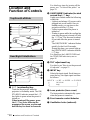
Unsuitable Installation ..................7
Unsuitable Conditions ..................7
Usage in High Altitude .................8
Features ..............................................8
Location and Function of Controls .10
Top/Front/Left Side ....................10
Rear/Right Side/Bottom .............10
Control Panel ..............................12
Connector Panel .........................12
Remote Commander ...................13
Setting Up and Projecting
Installing the Projector .....................17
Connecting the Projector ..................18
Connecting with a Computer ......18
Connecting with a VCR or 15k
RGB/Component
Equipment .......................20
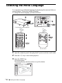
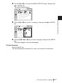
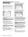
Selecting the Menu Language ..........22
Projecting .........................................24
Effective Tools for Your
Presentation .....................30
Adjustments and Settings
Using the Menu
Using the MENU ............................. 32
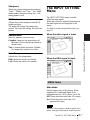
The PICTURE SETTING Menu ..... 34
The INPUT SETTING Menu .......... 35
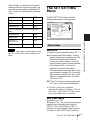
The SET SETTING Menu ............... 37
The MENU SETTING Menu .......... 38
The INSTALL SETTING Menu ..... 39
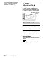
The INFORMATION Menu ............ 40
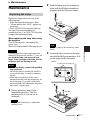
Maintenance
Maintenance .................................... 41
Replacing the Lamp ................... 41
Cleaning the Air Filter ............... 42
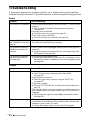
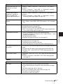
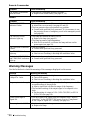
Troubleshooting ............................... 44
Warning Messages ..................... 46
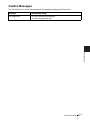
Caution Messages ...................... 47
Other
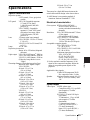
Specifications .................................. 49
Index ............................................... 54

GB
6 Precautions
B Overview
Precautions
On safety
• Check that the operating voltage of your
unit is identical with the voltage of your
local power supply.
• Should any liquid or solid object fall into
the cabinet, unplug the unit and have it
checked by qualified personnel before
operating it further.
• Unplug the unit from the wall outlet if it is
not to be used for several days.
• To disconnect the cord, pull it out by the
plug. Never pull the cord itself.
• The wall outlet should be near the unit and
easily accessible.
• The unit is not disconnected to the AC
power source (mains) as long as it is
connected to the wall outlet, even if the
unit itself has been turned off.
• Do not look into the lens while the lamp is
on.
• Do not place your hand or objects near the
ventilation holes. The air coming out is
hot.
• Be careful not to have your fingers caught
by the adjuster. The powered tilt adjuster
of this unit automatically extends when the
power is turned on, and is put away
automatically when the power is turned
off. Do not touch the unit while the
adjuster is in operation. Adjust the
powered tilt adjuster carefully after its
automatic operation is completed.
• Do not spread a cloth or paper under the
unit.
On illumination
• To obtain the best picture, the front of the
screen should not be exposed to direct
lighting or sunlight.
• Ceiling-mounted spot lighting is
recommended. Use a cover over
fluorescent lamps to avoid lowering the
contrast ratio.
• Cover any windows that face the screen
with opaque draperies.
• It is desirable to install the projector in a
room where floor and walls are not of
light-reflecting material. If the floor and
walls are of reflecting material, it is
recommended that the carpet and wall
paper be changed to a dark color.
On preventing internal heat build-
up
After you turn off the power with the I / 1
key, do not disconnect the unit from the wall
outlet while the cooling fan is still running.
Caution
The projector is equipped with ventilation
holes (intake) and ventilation holes
(exhaust). Do not block or place anything
near these holes, or internal heat build-up
may occur, causing picture degradation or
damage to the projector.
On cleaning
• To keep the cabinet looking new,
periodically clean it with a soft cloth.
Stubborn stains may be removed with a
cloth lightly dampened with a mild
detergent solution. Never use strong
solvents, such as thinner, benzene, or
abrasive cleansers, since these will
damage the cabinet.
• Avoid touching the lens. To remove dust
on the lens, use a soft dry cloth. Do not use
a damp cloth, detergent solution, or
thinner.
• Clean the filter at regular intervals.
On LCD data projector
• The LCD data projector is manufactured
using high-precision technology. You
may, however, see tiny black points and/or
bright points (red, blue, or green) that
continuously appear on the LCD data
projector. This is a normal result of the
manufacturing process and does not
indicate a malfunction.

7
GB
Notes on Installation
Overview
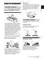
Notes on Installation
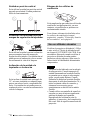
Do not install the projector in the following
situations. These installations may cause
malfunction or damage to the projector.
Poorly ventilated
• Allow adequate air circulation to prevent
internal heat build-up. Do not place the
unit on surfaces (rugs, blankets, etc.) or
near materials (curtains, draperies) that
may block the ventilation holes. When the
internal heat builds up due to the block-up,
the temperature sensor will function with
the message “High temp.! Lamp off in 1
min.” The power will be turned off
automatically after one minute.
• Leave space of more than 30 cm (11
7
/8
inches) around the unit.
• Be careful that the ventilation holes may
inhale tininess such as a piece of paper.
Highly heated and humid
• Avoid installing the unit in a location
where the temperature or humidity is very
high, or temperature is very low.
• To avoid moisture condensation, do not
install the unit in a location where the
temperature may rise rapidly.
Very dusty
Avoid installing the unit in a location where
there is a lot of dust; otherwise, the air filter
will be obstructed. The dust blocking the air
through the filter may cause raising the
internal heat of the projector. Clean it up
periodically.
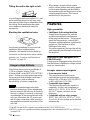
Do not use the projector under the following
conditions.
Toppling the unit
Avoid using as the unit topples over on its
side. It may cause malfunction.
Tilting the unit out of the range of
the adjuster setting
Avoid using when the unit is tilted out of the
range of the adjuster setting. Such
installation may cause color shading or
shorten excessively the lamp life.
Unsuitable Installation
Unsuitable Conditions

GB
8 Features
Tilting the unit to the right or left
Avoid tilting the unit to an angle of 15°, and
avoid installing the unit in any way other
than placing on the floor or suspending from
the ceiling. Such installation may cause
color shading or shorten the lamp life
excessively.
Blocking the ventilation holes
Avoid using something to cover over the
ventilation holes (exhaust/intake);
otherwise, the internal heat may build up.
For details on the ventilation holes (intake/
exhaust), see “Location and Function of
Controls” on page 10.
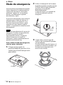
When using the projector at an altitude of
1,500 m or higher, turn on “High
Altitude Mode” in the INSTALL SETTING
menu. Failing to set this mode when using
the projector at high altitudes could have
adverse effects, such as reducing
the reliability of certain components.
• The unit is manufactured using high-
precision technology. When transporting
the unit stored in the soft case, do not drop
the unit or subject it to shock, as this may
cause damage. When storing the unit in the
soft case, disconnect the AC power cord
and all other connecting cables, and store
the supplied accessories in a pocket of the
soft case.
• When using a screen with an uneven
surface, stripes pattern may rarely appear
on the screen depending on the distance
between the screen and the projector or the
zooming magnifications. This is not a
malfunction of the projector.
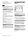
Features
High operability
• Intelligent Auto-setup function
Simply press the power key, and the
projector automatically performs the
setups required before use. The projector
opens the lens protector, corrects the V
Keystone, and sets optimum conditions for
projection. This function is called
Intelligent Auto-setup.
For easier operations, the keys that will be
used frequently are allocated on the top of
the projector.
Short focus lens equipped (VPL-
CS6/CX6 only)
This projector is equipped with a short focus
lens that allows outputting to a larger screen
even in a limited space.
Accepts various input signals
• Scan converter loaded
This projector has a build-in scan
converter that converts the input signal
within 1024 × 768 dots (VPL-CX6/EX1)
or 800 × 600 dots (VPL-CS6) .
• Compatible input signals
This projector accepts video signals of
composite, S video, and component as
well as VGA, SVGA, XGA, SXGA
1)
and
SXGA+
1)
signals, which all can be
displayed.
• Compatible with six color systems
NTSC, PAL, SECAM, NTSC
4.43
2)
, PAL-
M, or PAL-N color system can be selected
automatically.
Usage in High Altitude
Notes
..............................................................................................................................................................
1)The SXGA and SXGA+ signals are available for the VPL-CX6/EX1 only.
2)NTSC
4.43 is the color system used when playing back a video recorded on NTSC on a NTSC4.43
system VCR.

9
GB
Features
Overview
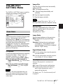
Easy presentation
• Simple setup with external equipment
This projector is preset for 38 kinds
3)
(VPL-CX6/EX1) of input signals. You can
project images from an external signal
source just by connecting the equipment
with the supplied cable.
You can use the supplied Remote
Commander as the wireless mouse by
connecting the projector to the computer
with the USB cable
4)
. You can also
control the projector by using the
application software (Projector Station)
5)
supplied with the projector from a
computer operated with Windows 98,
Windows 98 SE, Windows ME, Windows
2000 or Windows XP.
Easy-to-use Remote Commander
The Remote Commander is equipped with
various convenient keys, including the D
ZOOM key for zooming in on the image and
the FREEZE key for keeping the image
projected even if the equipment is
disconnected.
Memory Stick slot (VPL-CX6 only)
By inserting a Memory Stick into the built-
in Memory Stick slot, you can make the
presentation easily without connecting the
computer.
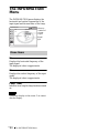
High brightness, high picture
quality
• High brightness
Adopting Sony’s unique, high-efficiency
optical system allows the 165 W UHP
lamp a light output of 2000 ANSI lumen
(VPL-CX6), 1800 ANSI lumen (VPL-
CS6) or 1500 ANSI lumen (VPL-EX1).
• High resolution
For VPL-CX6/EX1: Three superhigh-
aperture 0.7-inch XGA panels with
approximately 790,000 pixels, and with
micro-lens array, provide a resolution of
1024 × 768 dots (horizontal/vertical) for
RGB input, and 750 horizontal TV lines
for video input.
For VPL-CS6: Three superhigh-aperture
0.7-inch SVGA panels with
approximately 480,000 pixels provide a
resolution of 800 × 600 dots (horizontal/
vertical) for RGB input, and 600
horizontal TV lines for video input.
High portability
• Light weight/small size/simple design
This projector has been miniaturized to
approx. 2.7 kg (5 lb 15 oz) in weight and
B5-file size.
Its simple yet sophisticated design fits
comfortably in your office.
Security lock
By setting a password, you can enable the
security lock to function for this
projector.
..............................................................................................................................................................
3)The VPL-CS6 is preset for 25 kinds of input signals.
4)The Remote Commander available for the wireless mouse and the USB cable are supplied with
the VPL-CS6/CX6.
5)The application software (Projector Station) can be used with the VPL-CX6 only.
• Windows is a registered trademark of Microsoft Corporation in the United States and/or other
countries.
• IBM PC/AT, VGA, SVGA, XGA and SXGA are registered trademarks of the International
Business Machines Corporation, U.S.A.
• Kensington is a registered trademark of Kensington Technology Group.
• Macintosh is a registered trademark of Apple Computer, Inc.
• VESA is a registered trademark of Video Electronics Standard Association.
• Display Data Channel is a trademark of Video Electronics Standard Association.
• Memory Stick and are trademarks of Sony Corporation.

GB
10 Location and Function of Controls
Location and
Function of Controls
1 I / 1 (on/standby) key
Turns on the projector when the
projector is in standby mode. The ON/
STANDBY indicator around the I / 1
key lights in green when the power is
turned on.
When turning off the power, press
the I / 1 key twice following the
message on the screen, or press and
hold the key for about two seconds.
For details on steps for turning off the
power, see “To turn off the power” on
page 29.
2 ON/STANDBY indicator (located
around the
I / 1 key)
Lights up or flashes under the following
conditions:
– Lights in red when a AC power cord is
plugged into a wall outlet. Once in
standby mode, you can turn on the
projector with the I / 1 key.
– Lights in green when the power is
turned on.
– Flashes in green while the cooling fan
runs after the power is turned off with
the I / 1 key. The fan runs for about
90 seconds after the power is turned
off.
The ON/STANDBY indicator flashes
quickly for the first 60 seconds.
During this time, you cannot light up
the ON/STANDBY indicator with the
I / 1 key.
For details on the LAMP/COVER and
the TEMP/FAN indicators, see on
page 46.
3 TILT adjustment key
For details, see“How to use the powered
tilt adjuster” on page 11.
4 INPUT key
Selects the input signal. Each time you
press the key, the input signal switches
as follows:
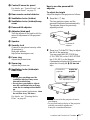
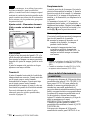
5 Lens protector (lens cover)
The lens protector automatically opens
when the power is turned on.
6 Front remote control detector
7 Ventilation holes (exhaust)
Top/Front/Left Side
Rear/Right Side/Bottom
TILT
INPUT A t MS t VIDEO t S VIDEO
t
(VPL-CX6
only)

11
GB
Location and Function of Controls
Overview
8 Control/Connector panel
For details, see “Control Panel” and
“Connector Panel” on page 12.
9 Rear remote control detector
0 Ventilation holes (intake)
qa Ventilation holes (intake)/Lamp
cover
qs Powered tilt adjuster
qd Adjuster (hind pad)
Turn the adjuster to the right or left for
minor tilt adjustment of the projected
picture.
qf Speaker
qg Security lock
Connects to an optional security cable
(Kensington’s).
Web page address:
http://www.kensington.com/
qh Focus ring
Adjusts the picture focus.
qj Zoom ring
Adjusts the picture size.
qk Ventilation holes (intake)/air
filter cover
• Do not place anything near the
ventilation holes as it may cause
internal heat build-up.
• Do not place your hand or objects
near the ventilation holes as it may
cause the air coming out heat build-
up.
• To maintain optimal performance, clean
the air filter every 300 hours.
For details, see “Cleaning the Air
Filter” on page 42.
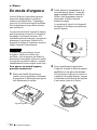
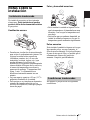
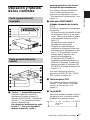
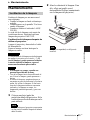
How to use the powered tilt
adjuster
To adjust the height
Adjust the height of the projector as follows:
1 Press the I / 1 key
The lens protector opens, and the
powered tilt adjuster rises automatically.
The adjuster stops at its previously
adjusted position.
2 Press f or F of the TILT key to adjust
the tilt of the projector.
You may press the KEYSTONE key
(VPL-CS6/CX6) or the D KEYSTONE
key (VPL-EX1) on the Remote
Commander to display the Tilt menu and
adjust the tilt using the M/m/</,
keys.
• Be careful not to let the projector down on
your fingers.
• Do not push hard on the top of the projector
with the powered tilt adjuster out.
It may be occurred malfunction.
Notes
Notes
Powered tilt
adjuster
TILT
to lower the
projector
to raise the
projector
TILT adjustment key
to raise the
projector

GB
12 Location and Function of Controls
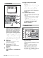
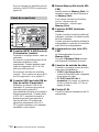
1 POWER SAVING indicator
Lights up when the projector is in power
saving mode. When “Power Saving” in
the SET SETTING menu is set to “ON,”
the projector goes into power saving
mode if no signal is input for 10 minutes.
Although the lamp goes out, the cooling
fan keeps running. The power saving
mode is canceled when a signal is input
or any key is pressed. In power saving
mode, any key does not function for the
first 60 seconds after the lamp goes out.
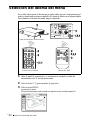
2 MENU key
Displays the on-screen menu. Press
again to clear the menu.
3 Arrow keys (f/F/g/G)
Select the menu or to make various
adjustments.
4 ENTER key
Enters the settings of items in the menu
system.
5 TEMP (Temperature)/FAN
indicator
Lights up or flashes under the following
conditions:
– Lights up when temperature inside the
projector becomes unusually high.
– Fashes when the fan is broken.
For details on the TEMP/FAN indicator,
see page 46.
6 LAMP/COVER indicator
Lights up or flashes under the following
conditions:
– Lights up when the lamp has reached
the end of its life or becomes a high
temperature.
– Flashes when the lamp cover or air
filter cover is not secured firmly.
For details on the LAMP/COVER
indicator, see page 46.
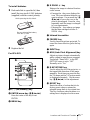
1 INPUT A connector (HD D-sub
15-pin, female)
Connect to external equipment such as a
computer.
Connects to the monitor output on a
computer using the supplied cable.
When inputting a component or 15k
RGB signal, use an optional cable.
For details, see “To connect a 15k RGB/
Component equipment” on page 21.
Control Panel
ACCESS
AUDIO VIDEO
POWER
SAVING
MENU
PUSH
ENTER
S VIDEO
TEMP/FAN
LAMP/COVER
INPUT A
PRO
ACCESS
AUDIO VIDEO
POWER
SAVING
MENU
PUSH
ENTER
S VIDEO
TEMP/FAN
LAMP/COVER
INPUT A
1
2
3
4
65
Connector Panel
AUDIO VIDEO
POWER
SAVING
MENU
PUSH
ENTER
S VIDEO
TEMP/FAN
LAMP/COVER
INPUT A
PRO
ACCESS
1
2
3
4
5
6
7

13
GB
Location and Function of Controls
Overview
2 USB connector (USB plug for
upstream, 4-pin)
Connect to the USB connector on a
computer. When you connect the
projector to the computer, you can
control the mouse function with the
supplied Remote Commander. (When
you use the VPL-EX1, an optional
Remote Commander is required to
control the mouse function with a
Remote Commander.) The supplied
application software (VPL-CX6 only)
can be installed in the computer attached
to this connector.
3 Memory Stick slot (VPL-CX6
only)
The Memory Stick can be inserted.
Never insert an object other than the
Memory Stick.
For details, see the attached “Operating
Instructions” for Memory Stick.
4 AUDIO (stereo minijack)
connector
When listening to sound output from the
computer, connect to the audio output of
the computer.
When listening to sound output from the
VCR, connect to the audio output of the
VCR.
5 Access lamp (VPL-CX6 only)
Lights during having access to the
Memory Stick.
Do not remove the Memory Stick
while the access lamp is lit.
6 Video input connector
Connect to external video equipment
such as a VCR.
• VIDEO (phono type): Connects to
the composite video output of video
equipment.
• S VIDEO (mini DIN 4-pin):
Connects to the S video output (Y/C
video output) of video equipment.
7 AC IN socket
Connects the supplied AC power cord.
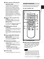
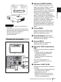
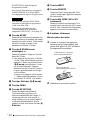
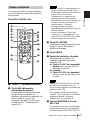
The keys that have the same names as those
on the control panel function identically.
For VPL-CS6/VPL-CX6
1
I / 1 (on/standby) key
2 APA (Auto Pixel Alignment) key
Adjusts a picture clearest automatically
while a signal is input from a computer.
Used when “Smart APA” in the SET
SETTING menu is set to “Off.”
Normally set to “On.”
• Press the APA key when the full image
is displayed on the screen. If there are
black edges around the image, the APA
function will not function properly and
the image may extend beyond the screen.
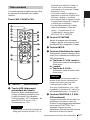
Remote Commander
Notes
I / 1
INPUT
PIC
FREEZE
MENU ENTER
KEYSTONE
MUTING
MS SLIDE
RESET
FUNCTION
D ZOOM
12
APA
+
–
R
CLICK
9
2
3
4
6
7
1
8
qa
qf
q
g
qd
qs
0
5
a
5
b
5
c

GB
14 Location and Function of Controls
• You can cancel the adjustment by
pressing the APA key again while
“Adjusting” appears on the screen.
• The picture may not be adjusted properly
depending on the kinds of input signals.
• Adjust the items “Dot Phase,” “H Size”
and “Shift” in the INPUT SETTING
menu when you adjust the picture
manually.
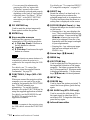
3 PIC MUTING key
Used to mute the picture temporarily.
Press again to restore the picture.
4 ENTER key
5 Keys emulate a mouse
Functions like a mouse of a computer
connected via USB with the projector.
a) L Click key (Rear): Functions as
the left button on a mouse.
b) Joystick
c) R Click key: Functions as the right
button on a mouse.
These keys function as mouse buttons of a
computer only when the projector is
connected to the computer using the USB
cable.
For details, see “To control the
computer using the supplied Remote
Commander” on page 26.
6 FUNCTION 1, 2 keys (VPL-CX6
only)
When you connect the projector with a
computer, you can open a file on the
screen by just pressing the FUNCTION
key. This will enhance your
presentation. To use this function,
allocate a file to the FUNCTION key by
using the supplied application software.
For details, see the README file and
the HELP file supplied with the
application software.
Connect a computer to the projector using
the USB cable to activate the FUNCTION
keys.
For details, see “To connect an IBM PC/
AT compatible computer” on page 19”.
7 RESET key
Resets the value of an item back to its
factory preset value or returns the
enlarged image back to its original size.
This key functions when the menu or a
setting item is displayed on the screen.
8 D ZOOM (Digital Zoom) +/– key
Enlarges the image at a desired location
on the screen.
+:Pressing the + key once displays the
icon. This icon indicates the point you
want to enlarge. Use an arrow key (M/
m/</,) to move the icon to the
point to be enlarged. Press the + key
repeatedly until the image is enlarged
to your requirements.
–: Pressing the – key reduces an image
that has been enlarged with the D
ZOOM + key.
9 Arrow keys (M/m/</,)
0 MENU key
qa KEYSTONE key
Used to adjust the tilt of the projector, or
the trapezoidal distortion of the image
manually. Each time you press this key,
the Tilt menu and the V Keystone menu
is displayed alternately. Use the arrow
keys (M/m/</,) for the adjustment.
qs INPUT key
qd FREEZE key
Used to freeze the picture projected. To
cancel the frozen picture, press the key
again.
qf MS SLIDE key (VPL-CX6 only)
Used to execute the slide show. When
the input signal is other than MS, it
switches to MS. To begin the slide show,
press the key again.
qg Infrared transmitter
Note
Note

15
GB
Location and Function of Controls
Overview
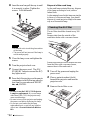
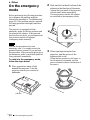
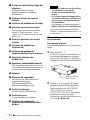
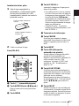
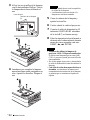
To install batteries
1 Push and slide to open the lid, then
install the two size AA (R6) batteries
(supplied) with the correct polarity.
2 Replace the lid.
For VPL-EX1
1 I / 1 (on/standby) key
2 ENTER/arrow key (M/m/</,)
Press the center of the key to use
ENTER.
3 MENU key
4 D ZOOM +/
– key
Enlarges the image at a desired location
on the screen.
+:Pressing the + key once displays the
icon. This icon indicates the point you
want to enlarge. Use an arrow key (M/
m/</,) to move the icon to the
point to be enlarged. Press the + key
repeatedly until the image is enlarged
to your requirements.
–:Pressing the – key reduces an image
that has been enlarged with the D
ZOOM + key.
5 Infrared transmitter
6 FREEZE key
Used to freeze the picture projected. To
cancel the freeze function, press the key
again.
7 INPUT key
8 APA (Auto Pixel Alignment) key
Adjusts a picture clearest automatically
while a signal is input from a computer.
Used when “Smart APA” in the SET
SETTING menu is set to “Off.”
Normally set to “On.”
9 D KEYSTONE key
Used to adjust the tilt of the projector, or
the trapezoidal distortion of the image
manually. Each time you press this key,
the Tilt menu and the V Keystone menu
is displayed alternately. Use the arrow
key (M/m/</,) for the adjustment.
q; RESET key
Resets the value of an item back to its
factory preset value or returns the
enlarged image back to its original size.
This key functions when the menu or a
setting item is displayed on the screen.
Be sure to install the battery
from the
# side.
While pressing the lid, slide it.

GB
16 Location and Function of Controls
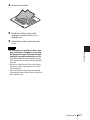
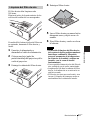
Before using the Remote
Commander
Pull out the clear film from the lithium
battery holder.
To replace battery
1 Release the lock of the lithium battery
holder by picking it, and pull out the
holder from the Remote Commander.
2 Install the lithium battery.
3 Put the lithium battery holder back
into the Remote Commander.
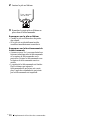
Notes on the lithium battery
• Keep the lithium battery out of the reach of
children.
• Should the battery be swallowed,
immediately consult a doctor.
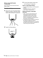
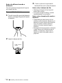
Notes on Remote Commander
operation
• Make sure that nothing obstructs the
infrared beam between the Remote
Commander and the remote control
detector on the projector. Direct the
Remote Commander toward the front or
rear remote control detector.
• The operation range is limited. The shorter
the distance between the Remote
Commander and the projector is, the wider
the angle within which the commander can
control the projector becomes.
+ side facing
upward

17
GB
Installing the Projector
Setting Up and Projecting
B Setting Up and Projecting
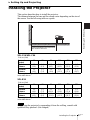
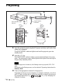
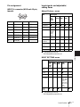
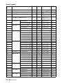
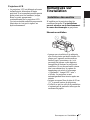
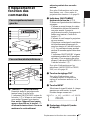
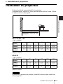
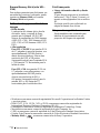
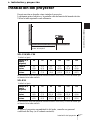
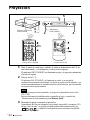
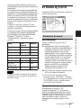
Installing the Projector
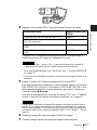
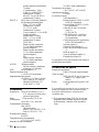
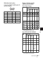
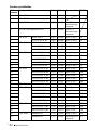
This section describes how to install the projector.
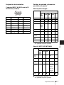
The distance between the lens and the screen varies depending on the size of
the screen. Use the following table as a guide.
VPL-CS6/VPL-CX6
There may be a slight difference between the actual value and the design value shown
in the table above.
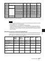
VPL-EX1
There may be a slight difference between the actual value and the design value shown
in the table above.
When using the projector by suspending it from the ceilling, consult with
qualified Sony personel. (fee charged)
Unit: m (feet)
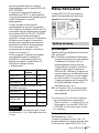
Screen size
(inches)
40 60 80 100 120 150
Minimum
Distance
1.2
(3.9)
1.9
(6.2)
2.5
(8.2)
3.2
(10.5)
3.8
(12.5)
4.7
(15.4)
Maximum
Distance
1.5
(4.9)
2.3
(7.6)
3.0
(9.8)
3.8
(12.5)
4.6
(15.1)
5.7
(18.7)
Unit: m (feet)
Screen size
(inches)
40 60 80 100 120 150
Minimum
Distance
1.5
(4.9)
2.3
(7.5)
3.1
(10.2)
3.9
(12.8)
4.7
(15.4)
5.9
(19.4)
Maximum
Distance
1.9
(6.2)
2.9
(9.5)
3.8
(12.5)
4.8
(15.7)
5.7
(18.7)
7.2
(23.6)
Note
Distance between the screen and
the center of the lens

GB
18 Connecting the Projector
Connecting the Projector
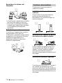
When you connect the projector, make sure to:
• Turn off all equipment before making any connections.
• Use the proper cables for each connection.
• Insert the cable plugs firmly; loose connections may increase noise and
reduce performance of picture signals. When pulling out a cable, be sure to
pull it out from the plug, not the cable itself
To connect the projector, refer to the illustrations on the next and the
following pages.
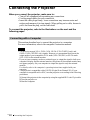
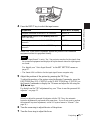
This section describes how to connect the projector to a computer.
For more information, refer to the computer’s instruction manual.
• The projector accepts VGA, SVGA, XGA, SXGA (VPL-CX6/EX1 only) and
SXGA+ (VPL-CX6/EX1 only) signals. However, we recommend that you set the
output mode of your computer to XGA mode (VPL-CX6/EX1) or SVGA mode
(VPL-CS6) for the external monitor.
• If you set your computer, such as a notebook type, to output the signal to both your
computer’s display and the external monitor, the picture of the external monitor may
not appear properly. Set your computer to output the signal to only the external
monitor.
For details, refer to the computer’s operating instructions supplied with your
computer.
• This projector is compatible with a DDC2B (Digital Data Channel 2B). If your
computer is compatible with a DDC, turn the projector on according to the following
procedures.
1 Connect the projector to the computer by using the supplied HD D-sub 15 pin cable.
2 Turn the projector on.
3 Start the computer.
Connecting with a Computer
Notes

19
GB
Connecting the Projector
Setting Up and Projecting
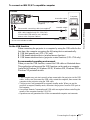
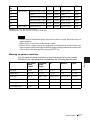
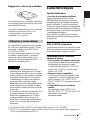
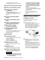
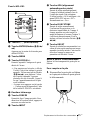
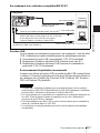
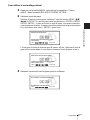
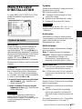
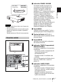
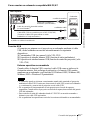
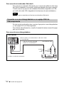
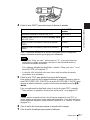
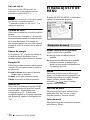
To connect an IBM PC/AT compatible computer
On the USB function
When connecting the projector to a computer by using the USB cable for the
first time, the computer recognizes the following devices automatically.
1 USB hub (general use) (VPL-CX6 only)
2 USB human interface device (wireless mouse function)
3 USB human interface device (projector control function) (VPL-CX6 only)
Recommended operating environment
When you use the USB function, connect the USB cable as illustrated above.
This application software and the USB function can be used on a computer
loaded with Windows 98, Windows 98 SE, Windows ME, Windows 2000 or
Windows XP preinstall models.
• Your computer may not start correctly when connected to the projector via the USB
cable. In this case, disconnect the USB cable, restart the computer, then connect the
computer to the projector using the USB cable.
• This projector is not guaranteed for suspend, standby mode. When you use the
projector in suspend, standby mode, disconnect the projector from the USB port on
the computer.
• An optional Remote Commander and USB cable are required when controlling the
mouse of the computer from the VPL-EX1.
• Operations are not guaranteed for all the recommended computer environments.
Notes
AUDIO VIDEO
POWER
SAVING
MENU
S VIDEO
TEMP/FAN
LAMP/COVER
INPUT A
PUSH
ENTER
PRO
ACCESS
to USB connector
Left side
HD D-sub 15-pin cable
(supplied)
Stereo audio connecting cable (not supplied)
a)
to monitor output
Computer
USB cable (supplied only VPL-CS6/CX6)
to audio output
a) Use a no-resistance cable.
(Connect the USB cable to use a wireless
mouse or the Projector Station.)

GB
20 Connecting the Projector
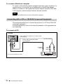
To connect a Macintosh computer
To connect a Macintosh computer equipped with video output connector of a
type having two rows of pins, use a commercially available plug adaptor.
When you connect a USB capable Macintosh computer using the USB cable
to the projector, wireless mouse functions become available.
The supplied software does not run on Macintosh computer.
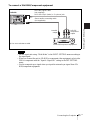
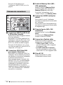
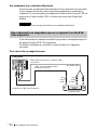
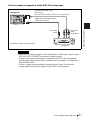
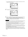
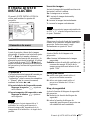
This section describes how to connect the projector to a VCR and 15k RGB/
component equipment.
For more information, refer to the instruction manuals of the equipment you
are connecting.
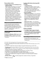
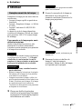
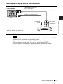
To connect a VCR
Note
Connecting with a VCR or 15k RGB/Component Equipment
AUDIO VIDEO
POWER
SAVING
MENU
S VIDEO
TEMP/FAN
LAMP/COVER
INPUT A
PUSH
ENTER
PRO
ACCESS
Stereo audio connecting cable
(not supplied)
a)
VCR
to S
video
output
Left side
to audio
output
Video cable (not supplied) or S-Video cable
(not supplied)
to video output
a) Use a no-resistance cable.
La page est en cours de chargement...
La page est en cours de chargement...
La page est en cours de chargement...
La page est en cours de chargement...
La page est en cours de chargement...
La page est en cours de chargement...
La page est en cours de chargement...
La page est en cours de chargement...
La page est en cours de chargement...
La page est en cours de chargement...
La page est en cours de chargement...
La page est en cours de chargement...
La page est en cours de chargement...
La page est en cours de chargement...
La page est en cours de chargement...
La page est en cours de chargement...
La page est en cours de chargement...
La page est en cours de chargement...
La page est en cours de chargement...
La page est en cours de chargement...
La page est en cours de chargement...
La page est en cours de chargement...
La page est en cours de chargement...
La page est en cours de chargement...
La page est en cours de chargement...
La page est en cours de chargement...
La page est en cours de chargement...
La page est en cours de chargement...
La page est en cours de chargement...
La page est en cours de chargement...
La page est en cours de chargement...
La page est en cours de chargement...
La page est en cours de chargement...
La page est en cours de chargement...
La page est en cours de chargement...
La page est en cours de chargement...
La page est en cours de chargement...
La page est en cours de chargement...
La page est en cours de chargement...
La page est en cours de chargement...
La page est en cours de chargement...
La page est en cours de chargement...
La page est en cours de chargement...
La page est en cours de chargement...
La page est en cours de chargement...
La page est en cours de chargement...
La page est en cours de chargement...
La page est en cours de chargement...
La page est en cours de chargement...
La page est en cours de chargement...
La page est en cours de chargement...
La page est en cours de chargement...
La page est en cours de chargement...
La page est en cours de chargement...
La page est en cours de chargement...
La page est en cours de chargement...
La page est en cours de chargement...
La page est en cours de chargement...
La page est en cours de chargement...
La page est en cours de chargement...
La page est en cours de chargement...
La page est en cours de chargement...
La page est en cours de chargement...
La page est en cours de chargement...
La page est en cours de chargement...
La page est en cours de chargement...
La page est en cours de chargement...
La page est en cours de chargement...
La page est en cours de chargement...
La page est en cours de chargement...
La page est en cours de chargement...
La page est en cours de chargement...
La page est en cours de chargement...
La page est en cours de chargement...
La page est en cours de chargement...
La page est en cours de chargement...
La page est en cours de chargement...
La page est en cours de chargement...
La page est en cours de chargement...
La page est en cours de chargement...
La page est en cours de chargement...
La page est en cours de chargement...
La page est en cours de chargement...
La page est en cours de chargement...
La page est en cours de chargement...
La page est en cours de chargement...
La page est en cours de chargement...
La page est en cours de chargement...
La page est en cours de chargement...
La page est en cours de chargement...
La page est en cours de chargement...
La page est en cours de chargement...
La page est en cours de chargement...
La page est en cours de chargement...
La page est en cours de chargement...
La page est en cours de chargement...
La page est en cours de chargement...
La page est en cours de chargement...
La page est en cours de chargement...
La page est en cours de chargement...
La page est en cours de chargement...
La page est en cours de chargement...
La page est en cours de chargement...
La page est en cours de chargement...
La page est en cours de chargement...
La page est en cours de chargement...
La page est en cours de chargement...
La page est en cours de chargement...
La page est en cours de chargement...
La page est en cours de chargement...
La page est en cours de chargement...
La page est en cours de chargement...
La page est en cours de chargement...
La page est en cours de chargement...
La page est en cours de chargement...
La page est en cours de chargement...
La page est en cours de chargement...
La page est en cours de chargement...
La page est en cours de chargement...
La page est en cours de chargement...
La page est en cours de chargement...
La page est en cours de chargement...
La page est en cours de chargement...
La page est en cours de chargement...
La page est en cours de chargement...
La page est en cours de chargement...
La page est en cours de chargement...
La page est en cours de chargement...
La page est en cours de chargement...
La page est en cours de chargement...
La page est en cours de chargement...
La page est en cours de chargement...
La page est en cours de chargement...
La page est en cours de chargement...
La page est en cours de chargement...
La page est en cours de chargement...
La page est en cours de chargement...
La page est en cours de chargement...
La page est en cours de chargement...
La page est en cours de chargement...
La page est en cours de chargement...
La page est en cours de chargement...
La page est en cours de chargement...
La page est en cours de chargement...
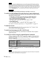
-
 1
1
-
 2
2
-
 3
3
-
 4
4
-
 5
5
-
 6
6
-
 7
7
-
 8
8
-
 9
9
-
 10
10
-
 11
11
-
 12
12
-
 13
13
-
 14
14
-
 15
15
-
 16
16
-
 17
17
-
 18
18
-
 19
19
-
 20
20
-
 21
21
-
 22
22
-
 23
23
-
 24
24
-
 25
25
-
 26
26
-
 27
27
-
 28
28
-
 29
29
-
 30
30
-
 31
31
-
 32
32
-
 33
33
-
 34
34
-
 35
35
-
 36
36
-
 37
37
-
 38
38
-
 39
39
-
 40
40
-
 41
41
-
 42
42
-
 43
43
-
 44
44
-
 45
45
-
 46
46
-
 47
47
-
 48
48
-
 49
49
-
 50
50
-
 51
51
-
 52
52
-
 53
53
-
 54
54
-
 55
55
-
 56
56
-
 57
57
-
 58
58
-
 59
59
-
 60
60
-
 61
61
-
 62
62
-
 63
63
-
 64
64
-
 65
65
-
 66
66
-
 67
67
-
 68
68
-
 69
69
-
 70
70
-
 71
71
-
 72
72
-
 73
73
-
 74
74
-
 75
75
-
 76
76
-
 77
77
-
 78
78
-
 79
79
-
 80
80
-
 81
81
-
 82
82
-
 83
83
-
 84
84
-
 85
85
-
 86
86
-
 87
87
-
 88
88
-
 89
89
-
 90
90
-
 91
91
-
 92
92
-
 93
93
-
 94
94
-
 95
95
-
 96
96
-
 97
97
-
 98
98
-
 99
99
-
 100
100
-
 101
101
-
 102
102
-
 103
103
-
 104
104
-
 105
105
-
 106
106
-
 107
107
-
 108
108
-
 109
109
-
 110
110
-
 111
111
-
 112
112
-
 113
113
-
 114
114
-
 115
115
-
 116
116
-
 117
117
-
 118
118
-
 119
119
-
 120
120
-
 121
121
-
 122
122
-
 123
123
-
 124
124
-
 125
125
-
 126
126
-
 127
127
-
 128
128
-
 129
129
-
 130
130
-
 131
131
-
 132
132
-
 133
133
-
 134
134
-
 135
135
-
 136
136
-
 137
137
-
 138
138
-
 139
139
-
 140
140
-
 141
141
-
 142
142
-
 143
143
-
 144
144
-
 145
145
-
 146
146
-
 147
147
-
 148
148
-
 149
149
-
 150
150
-
 151
151
-
 152
152
-
 153
153
-
 154
154
-
 155
155
-
 156
156
-
 157
157
-
 158
158
-
 159
159
-
 160
160
-
 161
161
-
 162
162
-
 163
163
-
 164
164


Sony VLP-CS6 Le manuel du propriétaire
- Catégorie
- Projecteurs de données
- Taper
- Le manuel du propriétaire
dans d''autres langues
- English: Sony VLP-CS6 Owner's manual
- español: Sony VLP-CS6 El manual del propietario
Documents connexes
-
Sony VPL-ES1 Mode d'emploi
-
-
-
-
Sony VPL-CX21 Mode d'emploi
-
Sony VPD-MX10 Manuel utilisateur
-
-
Sony VPL-CX80 Manuel utilisateur
-
-