
XBD-SPXM1
N

AGREEMENT: End user agrees to use this product in compliance with the instructions and
terms of use and with all State and Federal laws. STINGER provides instructions and safety
warnings with respect to this product and disclaims all liability for any use not in conjunction
with those instructions or other misuse of its product. If you do not agree, please discontinue
use and contact STINGER. This product is intended for off-road use and passenger use only.
TECHNICAL SUPPORT:
727-592-5991
Mon-Fri 9AM-8PM EST
Sat 9AM-7PM EST
Stinger is a Power Brand of AAMP Global
15500 Lightwave Drive, Suite 202
Clearwater, Florida 33760
CUSTOMER SOLUTIONS:
800-477-2267
Mon-Fri 9AM-8PM EST
Disconnect the vehicle's negative battery cable before making any wire connections.
Protect all vehicle surfaces with tape or plastic.
Do not install components in any location that will hinder vehicle operation, such as
steering wheel, gearshift, air bags, hazard switch.
Bundle cables and harnesses with electrical tape or wire ties to prevent them from
interfering with moving parts.
5L]LYH[[LTW[[VKPZHZZLTISLVYTVKPM`[OLWYVK\J[6[OLY^PZLHUHJJPKLU[ÄYLVY
electric shock may result.
,_WVZLK^PYLZT\Z[ILPUZ\SH[LK^P[OLSLJ[YPJHS[HWL6[OLY^PZLHZOVY[JPYJ\P[ÄYLVY
electric shock may result.
;VWYL]LU[KHTHNL[V[OL]LOPJSLJVUÄYT[OLSVJH[PVUZVMOVZLZLSLJ[YPJHS^PYPUNHUK
the fuel tank prior to drilling holes to install this product.
When it is necessary to replace the fuse, always use a fuse of the correct rating
U\TILYVMHTWLYLZ<ZLVMM\ZLZ^P[OOPNOLYHTWLYHNLYH[PUNZTH`JH\ZLHÄYL
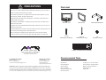
PRECAUTIONS Parts List
Recommended Tools
SOURCE UNIT TRIM PLATE MOUNTING BRACKET
POWER / SPEAKER WIRE HARNESS
3.5 X 25
MOUNTING SCREW (4)
M4 X 35
THREADED STUD (2)
M4
FLANGE NUTS (8)
Multimeter
Wire Strippers
Wire Cutters
Drill / Drill Bits
Phillips Screwdriver
Wire Crimpers
Cutting Tool / 3” Hole Saw
8mm Wrench (Flange Nuts)
Battery Terminal Wrench
Soldering Iron
Heat Gun

Optional Accessories Mounting Options
SPXR2
Wired Marine Remote
Control the SPXM1 from the swim
deck or seating area.
SPXSH440
Solid State Power Bank
Control external accessories
such as lighting, audio or any
other 12V accessory right from
the SPXM1 using the SPXSH440.
SEADASH3
Universal Marine 3” Radio Kit
Plastic bezel plate makes updating
a single DIN to 3” gauge style head
unit easy-peasy. Available in Black
and White.
SMRAUXUSB3
Marine USB & AUX Input
Molded connectors with machined,
nickel-plated, brass contacts offer
superior connection integrity, signal
transfer and maximum corrosion
resistance.
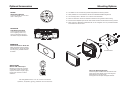
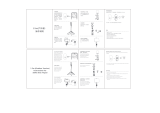
Using The Mounting Bracket
Insert and tighten threaded studs into back of radio.
Insert harness and chassis through mounting hole.
Slide U Bracket onto both studs.
Use supplied nuts to adjust and tighten bracket.
SPXR2
SOURCE
BAND
VOLUME
VOLUME
Visit StingerElectronics.com for a full line of Marine
ZWLHRLYZHTWSPёLYZSPNO[PUNIH[[LYPLZHUKHJJLZZVYPLZ
The SPXM1 can be mounted using the Mounting Bracket or Mounting Screws.
When possible, it is recommended to use both the U Bracket AND Mounting Screws.
The mounting hole is 3" diameter. A 3” hole saw is recommended.
4V\U[VUÅH[Z\YMHJL*OLJRMVYVIZ[Y\J[PVUZILOPUKTV\U[PUNSVJH[PVUILMVYLJ\[[PUN
Ensure there is adequate space for the radio chassis and wire harness behind mounting surface.
When using the U Bracket and plastic dash kit, do not overtighten, as it may cause discoloration
of the dash kit on the front face.
Threaded Studs

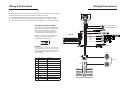
Wiring & Connections Wiring & Connections
PURPLE/WHITE REVERSE CAMERA TRIGGER INPUT (+)
13PIN DIN FEMALE
WIRED REMOTE
BLACK
GREY
RED
20A
USB
RADIO ANTENNA
RED (REAR LINE OUT RIGHT OR SUB-W OUT)
WHITE (REAR LINE OUT LEFT OR SUB-W OUT)
RED (FRONT LINE OUT RIGHT)
WHITE (FRONT LINE OUT LEFT)
RED (AUX IN RIGHT)
WHITE (AUX IN LEFT)
REAR/SUB LINE OUT
FRONT LINE OUT
AUX LINE IN
ORANGE/WHITE
GREEN/BLACK
GREEN
RED
WHITE
WHITE/BLACK
GRAY
GRAY/BLACK
BLUE/WHITE
PURPLE/BLACK
PURPLE
BLACK
ANTENNA INPUT
USB INPUT
REVERSE INPUT
VIDEO INPUT
1
23
4
56
78
9
101112
123
456
789
10 11 12
YELLOW - CAMERA / VIDEO INPUT
SWITCH 1 (12V+) WHITE/RED
SWITCH 2 (12V+) GRAY/RED
SWITCH 3 (12V+) GREEN/RED
SWITCH 4 (12V+) PURPLE/RED
PIN WIRE COLOR DESCRIPTION
1 GREEN REAR LEFT SPEAKER +
2 GREEN/BLACK REAR LEFT SPEAKER -
3 ORANGE/WHITE ILLUMINATION +
4 WHITE FRONT LEFT SPEAKER +
5 WHITE BLACK FRONT LEFT SPEAKER -
6 RED ACC 12V+
7 GRAY FRONT RIGHT SPEAKER +
8 GRAY/BLACK FRONT RIGHT SPEAKER -
9 BLUE//WHITE REMOTE/AMP TURN ON
10 PURPLE REAR RIGHT SPEAKER +
11 PURPLE/BLACK REAR RIGHT SPEAKER -
A
A
B
B
ACCESSORY CONTROL WIRING
The SPXM1 has 4 switchable outputs/triggers
(FIG. A) that can be used to control external
accessories such as lighting, audio or any
other 12V accessory, when used with the
optional SPXSH440 Power Bank System.
SWITCH 1-4 wires are 12V+ outputs and can
activated individually by accessing the
ACCESSORY CONTROL source.
WARNING!
Accessory control outputs are 100mA. Do not
connect directly to any accessories or conven-
tional relays. Failure to follow instructions may
result in damage to equipment and void the
device warranty.
FIG. A
Solder and heat shrink or waterproof butt connectors are recommened for all wire connections
RCA, USB and Antenna connections should be secured with heat shrink
The SPXM1uses EEPROM memory, so there is no (Yellow) wire connected to the battery
The Red (ACC 12V+) wire should be connected to switched power, not directly to battery
The Camera/Video Input can be triggered with the Purple/White wire or selected as a Source
PIN SIDE

:WLJPÄJH[PVUZ
74mm
2.91in
21.5mm
.85in
118mm
4.65in
98mm
3.85in
76mm
3.0in
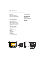
General
Operating Voltage:
Max Current:
Display: 2.7 inch Color TFT
Backlit Water Resistant Panel (IPX-6)
Remote Control: Wired (Optional)
Audio
Peak Power Output: 45W x 4
RMS Power Output: 25W x 4
Speaker Impedance: 4 ohm
RCA Outputs: 2 Pair(Front, Rear or Sub)
Preamp Voltage: 2 Volts
Frequency Response: 20-20kHz
Equalizer: 7 Band Graphic
Crossover: High Pass, Low Pass
Adjustable gain for each source
Tuner
AM/FM/Weather Bands
Presets: 18 FM, 12 AM, 6 WB
Local/Distant Selectable
Auto Store
Motorola Antenna Input
USB 2.0
Location: Rear
1 AMP Output
32GB Max
999 Songs Max
255 Folders Max
File Types: MP3/WMA/WAV
AUX Input
Location: Rear
Input Type: Stereo RCA
Camera/Video Input
Location: Rear
Input Type: RCA
Video Format: PAL/NSTC
External & Internal Trigger
Bluetooth
Version: 3.0+EDR, A2DP 1.3

FCC statements:
This device complies with part 15 of the FCC rules. Operation is subject to the
following two conditions: (1) this device may not cause harmful interference, and (2)
this device must accept any interference received, including interference that may
cause undesired operation.
NOTE: The manufacturer is not responsible for any radio or TV interference caused
by unauthorized modifications or changes to this equipment. Such modifications or
changes could void the user’s authority to operate the equipment.
NOTE: This equipment has been tested and found to comply with the limits for a
Class B digital device, pursuant to part 15 of the FCC Rules. These limits are designed
to provide reasonable protection against harmful interference in a residential
installation. This equipment generates uses and can radiate radio frequency energy
and, if not installed and used in accordance with the instructions, may cause harmful
interference to radio communications. However, there is no guarantee that
interference will not occur in a particular installation. If this equipment does cause
harmful interference to radio or television reception, which can be determined by
turning the equipment off and on, the user is encouraged to try to correct the
interference by one or more of the following measures:
‐ Reorient or relocate the receiving antenna.
‐ Increase the separation between the equipment and receiver.
‐Connect the equipment into an outlet on a circuit different from that to which the
receiver is connected.
‐Consult the dealer or an experienced radio/TV technician for help.
The device has been evaluated to meet general RF exposure requirement, The device
can be used in portable exposure condition without restriction. Federal
Communication Commission (FCC) Radiation Exposure Statement Power is so low
that no RF exposure calculation is needed.
IC statements:
RSS‐Gen & RSS‐247 statement:
Le présent appareil est conforme aux CNR d'Industrie Canada applicables
aux appareils radio exempts de licence.
L'exploitation est autorisée aux deux conditions suivantes :
(1) l'appareil ne doit pas produire de brouillage, et
(2) l'utilisateur de l'appareil doit accepter tout brouillage
radioélectrique subi, même si le brouillage est susceptible d'en
compromettre le fonctionnement.
Attention : exposition au rayonnement de radiofréquences
Cet équipement est conforme aux limites d'exposition aux

radiofréquences IC fixées pour un environnement non contrôlé et aux
Lignes directrices relatives à l'exposition aux radiofréquences (RF).
Co‐location
Ce transmetteur ne peut pas être installé en colocation ou être utilisé
avec une autre antenne ou transmetteur, quel qu'en soit le type.
This Class B digital apparatus complies with Canadian ICES-003.
(Cet appareil numérique de la classe B est conforme à la norme NMB-003 du
Canada.)
-
 1
1
-
 2
2
-
 3
3
-
 4
4
-
 5
5
-
 6
6
-
 7
7


dans d''autres langues
- English: Stinger SPXM1 Installation guide
Autres documents
-
 UGREEN LP586 Mode d'emploi
-
Panasonic NNSD452W Le manuel du propriétaire
-
Testo 316I Manuel utilisateur
-
Clarion XC1410 Guide d'installation
-
Fusion MS-UD/AV750 Guide de démarrage rapide
-
Eclipse - Fujitsu Ten AVN4400 Manuel utilisateur
-
-
Kenwood DDX 5706 S Manuel utilisateur
-
Clarion CMS 1 Le manuel du propriétaire
-
Clarion M606 Manuel utilisateur
