

Änderu nge n vorbe halte n Stand 31.08.0 4
ipcas GmbH ipEther232 V10.21 Seite 2 von 98
Legal information for customers
We have done our utmost to ensure that the information in this user guide is
complete, accurate and up to date. In so far as legally possible, we cannot
accept any liability for consequential damage caused by using this guide. In
other respects we shall accept liability for intention and gross negligence only.
We cannot provide any warranty that changes to third-party equipment referred
to in this guide will have no effect on the applicability of the information provided
in this guide.
The author reserves all rights, including the right to reproduce this guide in full or
part thereof in any form whatsoever.
The content is subject to change without prior notification.
The product is subject to technical change without prior notification.
Trade marks are stated for identification purposes and may be the property of
the various holders.
Important Information
• The device should be used exclusively with the mains unit supplied. Using
a different power supply unit may lead to the device being damaged.
• Use a dry cloth only to clean the operating panel and the housing.
• If the device is damaged, disconnect from the mains. Arrange for
immediate repair.
• Before contacting your vendor's customer service, please consult this user
guide.
• During the warranty period, resorting to the customer service may incur
costs, if the fault or problem was caused by the customer and the solution
or remedy is described in this guide.
• Removing the seri al number will voi d the warranty ri ghts.
• Damage caused by inappropriate packing will not be borne by the
forwarding agent / insurance company.
Note !
Applies only to metal housing with top hat rail assembly.
IpEther232 is a Class A device. This device can cause radio interferences in
residentail areas; in such cases the operator can be ordered to carry out and pay
for appropriate measures.
This warning does not apply to desktop housing or the OEM version without
housing.

Änderu nge n vorbe halte n Stand 31.08.0 4
ipcas GmbH ipEther232 V10.21 Seite 3 von 98
Important safety information
As is the case with all electrical equipment there are some basic safety
precautions that you should apply. These safety precautions are primarily for you
own safety but also serve to prevent damage to the device.
Settings not described in this guide and changes to the device electronics are to
be carried out by an authorized vendor only.
Read the user guide carefully and keep it to hand.
M a ke su re tha t…
• the device is placed on a stable, flat surface;
• for rail mounted devices the top hat rail is sufficiently grounded and the
rail spring has good contact;
• the device is never placed near a heater or the air outlet of an
ai rcondi ti oni ng unit;
• the device is never exposed to direct sunlight;
• the device is never in direct contact with liquids of any kind. Therefore
never use liquids in the vicinity of the device.
• Opening the housing may lead to an electric shock and other damage.
Never make any changes to the device that are not descri bed i n the user
guide. This could damage the device and you will have to pay for the
repairs. Only the authorized vendor may change the input voltage,
should this become necessary.
Install the device
Make sure that...
• the mains supply values are the same as the designation on the mains
supply unit. In case of doubt contact your supplier.
• the mains is protected against surges and other disturbances.
• the mains socket is located near the device and is easily accessible.
• you pull the mains plug completely to disconnect.
• the maximum power rating of an extension cable or multiple contact
plug, if used, is not exceeded.
• the mains cable is protected against damage. Do not place anything on
the cable and put it down, so that there is no danger of stepping on or
tripping over it.
• a damaged mains cable is replaced immediately.
• the mains cable is disconnected before starting to clean the device. Use
a dry cloth only. Do not use any liquid or aerosol cleaning agent.

Änderu nge n vorbe halte n Stand 31.08.0 4
ipcas GmbH ipEther232 V10.21 Seite 4 von 98
Please follow all warnings and instructions displayed on the device itself
and in accompanying manuals. In the manual, warnings of particular
importance are marked by the symbols below.
Warning and important information symbols
NOTE: Text sections marked in this way contain supplementary information or hints.
WARNING - damage: This marking warns against possible damage to the device.
Follow all instructions to avoid damage.
CAUTION - Danger of injury: This marking points out a possible source of danger.
Follow all safety instructions to avoid injury.
CAUTION - Hot: This marking points out a possible source of danger. Follow all safety
instructions to avoid heat-related injury.
CAUTION - Current: This marking points out a possible source of danger. Follow all
safety instructions to avoid injury through electrocution.

Änderu nge n vorbe halte n Stand 31.08.0 4
ipcas GmbH ipEther232 V10.21 Seite 5 von 98
Contents Page
Chapter 1: The Device..................................................................7
1.1 Sockets .......................................................................................................................... 7
1.2 Usage ipEther232 (virtual ComPort)......................................................................... 9
1.3 Usage ipEther232.Modem (Ethernet modem).......................................................10
1.4 Usage ipEther232.PPP (PPP – Gateway) .............................................................12
1.5 Usage ipNTP (SNTP Timeserver)...........................................................................14
Chapter 2: Commissioning the ipEther232..................16
2.1 Installation ...................................................................................................................16
2.2 Configurationtool........................................................................................................16
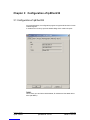
Chapter 3: Configuration of ipEther232........................21
3.1 Configuration of ipEther232......................................................................................21
3.2 Technical details for ipEther232 ..............................................................................27
Chapter 4: Configuration of ipEther232.Modem.......30
4.1 Configuration of ipEther232.Modem .......................................................................30
4.2 Serial Configuration ...................................................................................................36
4.3 Configure Password Protection (Serial Devices only).........................................37
4.4 ipEtherModem.inf (Driver-File)................................................................................38
4.5 Control Comm ands....................................................................................................41
4.6 AT Command Input and Execution.........................................................................41
4.7 Transmission Mode ...................................................................................................41
4.8 Quick Reference for AT Comm ands and Registers.............................................42
4.9 Definition of AT Commands and Registers...........................................................43
4.10 Chart of AT Commands..........................................................................................43
4.11 Register Chart..........................................................................................................46
4.12 Result Code..............................................................................................................53
4.13 Technical details for ipEther232.Modem..............................................................54
Chapter 5: Configuration of ipEther232.PPP..............56
5.1 Configuration of ipEther232.PPP.............................................................................56
5.2 Logfile...........................................................................................................................61
5.3 Configuration samples...............................................................................................63
5.4 Technical details for ipEther232.PPP.....................................................................66

Änderu nge n vorbe halte n Stand 31.08.0 4
ipcas GmbH ipEther232 V10.21 Seite 6 von 98
Chapter 6: Configuration of ipNTP...................................68
6.1 Configuration of ipNTP..............................................................................................68
6.2 SNTP-Clients..............................................................................................................73
6.3 DCF77-Antenna and DB9 Clamp............................................................................77
6.4 Technical details for ipNTP.......................................................................................77
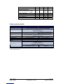
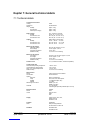
Kapitel 7: General technical details .................................79
7.1 Technical details.........................................................................................................79
7.2 Pin allocation...............................................................................................................80
7.3 RS232 Connection Cable.........................................................................................82
7.4 Pin allocation for ipEther232.Modem OEM............................................................84
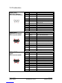
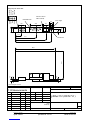
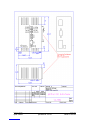
7.5 Power supply modules..............................................................................................86
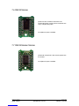
7.6 RS232 Module............................................................................................................87
7.7 RS232.Modem Module.............................................................................................87
7.8 RS485 Module............................................................................................................88
7.9 RS485 as a 2 wire solution.......................................................................................89
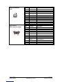
7.10 Measurements..........................................................................................................90
7.11 Statement of EEC Compliance..............................................................................93
7.12 FAQ’s .........................................................................................................................94
7.13 Glossary ....................................................................................................................98

Änderu nge n vorbe halte n Stand 31.08.0 4
ipcas GmbH ipEther232 V10.21 Seite 7 von 98
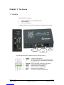
Chapter 1: The Device
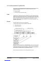
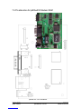
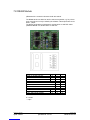
1.1 Sockets
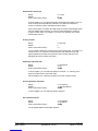
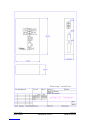
i pEther232 has three sockets:
• Ethernet (10BaseT) for a 10/100 Mbit network
• RS232 SUB-D 9
• 9V DC mains supply
A diagram of all connectors and their designation is displayed on the housing.
The LEDs indicate the device state and have the following meaning:
• POWER The device is switched on.
• System Slow flashing indicates that at the moment there is
no connection to a PC. Fast flashing indicates that
the device is in use.
• LINK LAN There is a physical connection to the network.
• LAN Rx Packets are received by the Ethernet.
• LAN Tx Packets are sent to the Ethernet.
• V24 Rx Data is received via the RS232 line.
• V24 Tx Data is sent via the RS232 line.
• Error An error has occured in the RS232 line.
RS232
SUB-D 9 Pin
Ethernet
10/100
RJ45
9V DC

Änderu nge n vorbe halte n Stand 31.08.0 4
ipcas GmbH ipEther232 V10.21 Seite 8 von 98
Exception ipNTP, here the LEDs have the following meaning:
• POWER The device is switched on.
• System Slow flashing indicates that at the moment there is
no synchronisation. Fast flashing indicates that the
device is in use.
• LINK LAN There is a physical connection to the network.
• LAN Rx Packets are received by the Ethernet.
• LAN Tx Packets are sent to the Ethernet.
• SECOND Second impulse is received by the DCF-77.
• MINUTE Mi nute impulse i s recei ved by the DCF-77.
• ANTENNA DCF-77 signal is lost.

Änderu nge n vorbe halte n Stand 31.08.0 4
ipcas GmbH ipEther232 V10.21 Seite 9 von 98
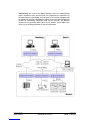
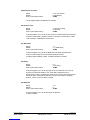
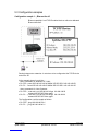
1.2 Usage ipEther232 (virtual ComPort)
ipEther232 enables you to use serial interfaces via a TCP/IP
network, LAN oder WAN.
This allows you to control devices without a network interface
over long distances.
Such devices are:
• modems
• printers
• SPS controls
• embedded controllers
Integration in the Windows environment is realized via a driver
which supplies a virtual serial "COM" interface.
Aus Sicht der Applikation sehen die virtuellen COM-Schnittstellen
wie lokale, im PC eingebaute, Schnittstellen aus. Auch das
Verhalten der Schnittstelle entspricht weitestgehend dem einer
physikalischen COM-Schnittstelle. An einem PC können bis zu
255 virtuelle Schnittstellen installiert werden.
COM
2
COM
3
Ether net/TCP/IP

Änderu nge n vorbe halte n Stand 31.08.0 4
ipcas GmbH ipEther232 V10.21 Seite 10 von 98
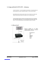
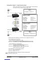
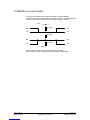
1.3 Usage ipEther232.Modem (Ethernet modem)
ipEther232.Modem enables you to use serial interfaces via a TCP/IP network. .
This allows you to control devices without a network interface over long
distances. In addition to the serial interface, the Ethernet modem also has a
network interface. In order to connect two serial devices simply use two modems
linked via Ethernet instead of a serial cable.
ö Terminals
ö CNC controllers
ö Counting devi ces
Such devices are: ö Embedded controllers
ö Industrial switches
ö Serial printers
ö SPS controllers
ö Card scanners
ö Measuring equipment
ö UPSs
Thus all applications and devices that support terminal or modem functionalities
can also be used via the Ethernet. This has numerous advantages:
• lower telephone costs
• reduce the number of analog connections (monthly fee)
• si m pl ifie d lo gi st i cs
• extremely low porting costs
• protects your investments by converting serial devices into network
devices without necessitating changes in the existing software, saving
additional product development costs
• versatile power supply and optimal housing solutions
• serial devices can be used by several clients
• automatic setup of network connection after interruptions
• easy to setup and suitable for larger installations
• si m pl e integration of seri al appli cations

Änderu nge n vorbe halte n Stand 31.08.0 4
ipcas GmbH ipEther232 V10.21 Seite 11 von 98
"Networking" w ill soon be the global standard. How ever, manufacturers
require expensive labor, precious time and comprehensive experience to
develop netw ork technologies. As most devices are already equipped w ith
an RS232/485 interface, the Ethernet modem offers an instant and efficient
solution for transmitting RS232/485 data via the netw ork. The Ethernet
modem not only provides added value to your product, it also adds to the
value of your existing equipment for the next generation.

Änderu nge n vorbe halte n Stand 31.08.0 4
ipcas GmbH ipEther232 V10.21 Seite 12 von 98
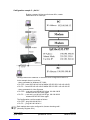
1.4 Usage ipEther232.PPP (PPP – Gateway)
The PPP / Ethernet – Converter enables the transmission of network packets via
a serial interface from and to the Ethernet (PPP = Point to Point Protocol).
With ipEther232.PPP all these (serial) devices can be linked up to an Ethernet
LAN via TCP/IP and thus also to the internet or your company intranet.
The PPP gateway solution works with all operating systems and is compatible
with existing PPP applications. You can start several services (ftp, telnet, www,
ssh, rsh, rcp etc.) simultaneously via this transparent network connection.
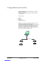
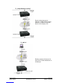
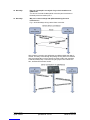
1.) „Ethernet for all“
Ethernet capability for all TCP/IP
enabled devices w ithout a dedicated
Ethernet interface, such as:
- Embedded PC
- SPS
- PC
- Notebook
- Modem
- Router
- Pa l m

Änderu nge n vorbe halte n Stand 31.08.0 4
ipcas GmbH ipEther232 V10.21 Seite 13 von 98
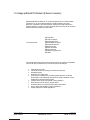
2.) „simple Network routing“
Simple routing betw een two
netw orks via GSM, ISDN or analog
modems, for instance to link up a
branch to the company LAN.
3.) „dial in“
Enables company LAN access for
home office, remote maintenance or
for field reps.

Änderu nge n vorbe halte n Stand 31.08.0 4
ipcas GmbH ipEther232 V10.21 Seite 14 von 98
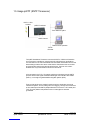
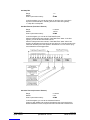
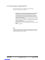
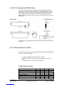
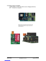
1.5 Usage ipNTP (SNTP Timeserver)
The ipNTP Standalone Timeserver can transmit DCF77 / GPS time information
onto computers, controllers or other dynamically critical devices / applications
over the ethernet. The client first determines the messial transmission time for the
data exchange with the time server. After that the client fetches the current time
and patches this value around the transmission time. The time on the client
deviates then only a few milliseconds from the timeserver.
All components in the TCP / IP network could be synchronized over the SNTP
protocol with the time signal transmitter Mainflingen near Frankfurt at the Main
(DCF77), or through the global satellite navigation system (GPS).
Time-precise solutions are needed in task executions, schedulers, personnel
information systems, time recordings and error logging. Through the commitment
of the network protocols SNTP (Simple Network Time Protocol – RFC 2030) and
TCP / IP is the platform independence even in heterogenous networks
guaranteed.
DCF77 / GPS
A
ntenna ipNTP
-
TimeServe
r
Ti me detection system
Task execution operation
TCP/IP
Ethernet
SNTP
-
Protocol

Änderu nge n vorbe halte n Stand 31.08.0 4
ipcas GmbH ipEther232 V10.21 Seite 15 von 98
NTP Server - Information
The network time protocol (NTP) is used in order to synchronize the time of a
client over the Internet/Intranet with other computers or with an external clock.
The primary NTP timeservers are over external timers locked maximally exactly
to the Coordinated Universal Time (UTC). The NTP Client synchronize the time
with NTP commands with the servers indicated as an argument.
DCF77 - Information
The DCF77 radio clocks receive the official time of the federal republic of
Germany from the physical-technical federal institution (PTB) in Braunschweig
and transmit the signal over different interfaces to computers and systems. The
long-term accuracy of the PTB calibrating standard measure is achieved by radio
alignment of the sender DCF77 in Mainflingen at Frankfurt/Main of 1 x10 E-13
weekly. Due to the high accuracy only this time is recognized as legally binding in
the federal republic.
GPS - Information
In approx. 20.000 km high satellites are moving on different railroads around the
earth. In every satellite is a nuclear clock (min. accuracy 1x 10 E-12), whose time
is send out continuously with the orbital data. The GPS-receiver registers the
dates of a minimum of 3 and maximum of 6 satelites and calculates his position
from these values. If the position is computed, the terms of the dates can be
determined by the individual satellites. From these values the GPS world time is
determined in the timeserver and continued about a variable quartz time exactly.

Änderu nge n vorbe halte n Stand 31.08.0 4
ipcas GmbH ipEther232 V10.21 Seite 16 von 98
Chapter 2: Commissioning the ipEther232
2.1 Installation
Connect the device to the mains. The "Power“ signal and the flashing "System“
LED indicate that ipEther232 is ready for operation.
ipEther232 is connected to the network via an RJ45 socket.
The "Link LAN“ LED (connection) indicates the connection to the LAN.
If this is not the case, check the netwok connection or network line.
The enclosed CD contains a driver set-up program and the configuration tool.
The driver runs on all Windows NT based operating systems, therefore Windows
NT with SP5, Windows 2000 and Windows XP.
No PC reboot is necessary after installation. The configuration tools starts
automatically after installation.
For later configuration sessions the program is included in the "Program files -
ipcas GmbH – ipEther Products“ folder.
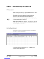
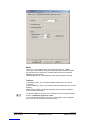
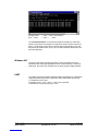
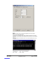
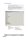
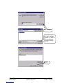
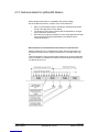
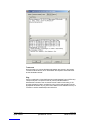
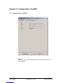
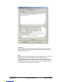
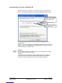
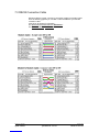
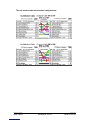
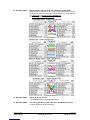
2.2 Configurationtool
The configuration program recognizes all devices in its own network segment,
even if they do not have a valid IP address.
By clicking on a column in the overview border (e.g.: “IP Address”) all found
devices are sorted for a better overview.

Änderu nge n vorbe halte n Stand 31.08.0 4
ipcas GmbH ipEther232 V10.21 Seite 17 von 98
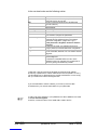
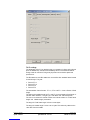
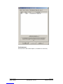
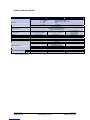
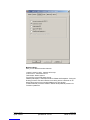
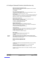
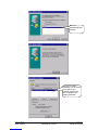
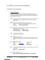
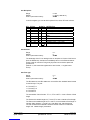
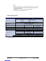
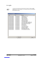
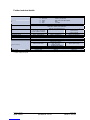
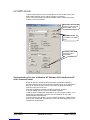
In the overview border are the following entries:
ID Device-id
Name Info (Comments could be very helpful to find a
particular device very quickly)
Info Current configured ComPort (only at ipEther232
„virtual ComPort“)
IP Address Current IP-Address
MAC MAC-Address
Dev ice Type Firmwaretype of the device
Version Current Fi rmwareversion
In Use If this entry is „True“, the device is already in use and
you shouldn`t configure the parameters.
Passw ort required If this entry is „True“, the device is password-
protected and the password have to be entered
before the configuration. (Right-click “Login”)
If the passw ord is forgotten, the device must be
returned.
Logged in If this entry is „False“, the password (Right-click
„Login“) have to be entered before the configuration.
Ping OK If this entry is „False“, the device couldn`t be found. It
is not connected, switched of or is in another network
segment.
in local Net If this entry is „False“, the device is not in the local
network segment.
If the device is installed behind a router, the IP-
Address couldn`t be changed. This prevents that a
device is getting inaccessible by mistake.
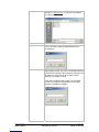
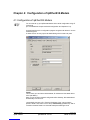
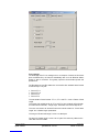
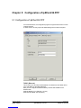
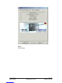
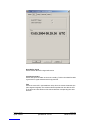
T o start wi th, each device must be al located an unambi guous IP address.
On delivery of ipEther232 no valid IP-Address has been set (Default: 10.10.5.1).
The IP-Address can be obtained from the network administrator. It must comply
with your network and cannot be assigned twice.
If you are embedded in a DHCP network, you`ll have to recieve a static
IP-Address from your network administrator for your ipEther232.
In order to set the IP address in your ipEther232, the device must be connected
to its own network segment.
If need be, connect the device via a "cross over“ cable to the PC.


Änderu nge n vorbe halte n Stand 31.08.0 4
ipcas GmbH ipEther232 V10.21 Seite 19 von 98
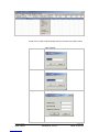
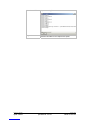
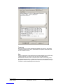
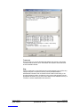
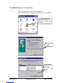
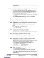
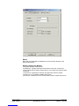
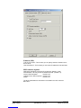
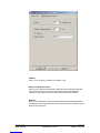
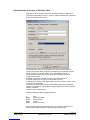
Upload Firmware Update new firmware. You can find new versions of the
firmware on www.ipcas.de . You should only update if
you really need to.
Delete Delete current marked entry
Login If the device is password protected (Passwort required =
„True“) you have to enter the password before the
configuration.
Add Manually If ipEther232 is connected after a router, they are not
automatically located. They have to be entered manually
("Add Device manually“).This requires the entering of the
IP address. If the device can be accessed via this
address, it is included in the list.
If the device is installed after a router, the IP address
couldn`t be changed, as otherwise the device might
become inaccessible by mistake.

La page est en cours de chargement...
La page est en cours de chargement...
La page est en cours de chargement...
La page est en cours de chargement...
La page est en cours de chargement...
La page est en cours de chargement...
La page est en cours de chargement...
La page est en cours de chargement...
La page est en cours de chargement...
La page est en cours de chargement...
La page est en cours de chargement...
La page est en cours de chargement...
La page est en cours de chargement...
La page est en cours de chargement...
La page est en cours de chargement...
La page est en cours de chargement...
La page est en cours de chargement...
La page est en cours de chargement...
La page est en cours de chargement...
La page est en cours de chargement...
La page est en cours de chargement...
La page est en cours de chargement...
La page est en cours de chargement...
La page est en cours de chargement...
La page est en cours de chargement...
La page est en cours de chargement...
La page est en cours de chargement...
La page est en cours de chargement...
La page est en cours de chargement...
La page est en cours de chargement...
La page est en cours de chargement...
La page est en cours de chargement...
La page est en cours de chargement...
La page est en cours de chargement...
La page est en cours de chargement...
La page est en cours de chargement...
La page est en cours de chargement...
La page est en cours de chargement...
La page est en cours de chargement...
La page est en cours de chargement...
La page est en cours de chargement...
La page est en cours de chargement...
La page est en cours de chargement...
La page est en cours de chargement...
La page est en cours de chargement...
La page est en cours de chargement...
La page est en cours de chargement...
La page est en cours de chargement...
La page est en cours de chargement...
La page est en cours de chargement...
La page est en cours de chargement...
La page est en cours de chargement...
La page est en cours de chargement...
La page est en cours de chargement...
La page est en cours de chargement...
La page est en cours de chargement...
La page est en cours de chargement...
La page est en cours de chargement...
La page est en cours de chargement...
La page est en cours de chargement...
La page est en cours de chargement...
La page est en cours de chargement...
La page est en cours de chargement...
La page est en cours de chargement...
La page est en cours de chargement...
La page est en cours de chargement...
La page est en cours de chargement...
La page est en cours de chargement...
La page est en cours de chargement...
La page est en cours de chargement...
La page est en cours de chargement...
La page est en cours de chargement...
La page est en cours de chargement...
La page est en cours de chargement...
La page est en cours de chargement...
La page est en cours de chargement...
La page est en cours de chargement...
La page est en cours de chargement...
-
 1
1
-
 2
2
-
 3
3
-
 4
4
-
 5
5
-
 6
6
-
 7
7
-
 8
8
-
 9
9
-
 10
10
-
 11
11
-
 12
12
-
 13
13
-
 14
14
-
 15
15
-
 16
16
-
 17
17
-
 18
18
-
 19
19
-
 20
20
-
 21
21
-
 22
22
-
 23
23
-
 24
24
-
 25
25
-
 26
26
-
 27
27
-
 28
28
-
 29
29
-
 30
30
-
 31
31
-
 32
32
-
 33
33
-
 34
34
-
 35
35
-
 36
36
-
 37
37
-
 38
38
-
 39
39
-
 40
40
-
 41
41
-
 42
42
-
 43
43
-
 44
44
-
 45
45
-
 46
46
-
 47
47
-
 48
48
-
 49
49
-
 50
50
-
 51
51
-
 52
52
-
 53
53
-
 54
54
-
 55
55
-
 56
56
-
 57
57
-
 58
58
-
 59
59
-
 60
60
-
 61
61
-
 62
62
-
 63
63
-
 64
64
-
 65
65
-
 66
66
-
 67
67
-
 68
68
-
 69
69
-
 70
70
-
 71
71
-
 72
72
-
 73
73
-
 74
74
-
 75
75
-
 76
76
-
 77
77
-
 78
78
-
 79
79
-
 80
80
-
 81
81
-
 82
82
-
 83
83
-
 84
84
-
 85
85
-
 86
86
-
 87
87
-
 88
88
-
 89
89
-
 90
90
-
 91
91
-
 92
92
-
 93
93
-
 94
94
-
 95
95
-
 96
96
-
 97
97
-
 98
98


dans d''autres langues
- English: IpCAS ipNTP User manual
Documents connexes

Autres documents
-
 BossPac EA000405 Border Router Manuel utilisateur
-
MicroNet SP3352 Manuel utilisateur
-
 Ditel DR189 Quick Start
-
VTech VNT814 Manuel utilisateur
-
VTech VNT832 Manuel utilisateur
-
Multitech MT200A2EW-H5-WW Mode d'emploi
-
-
Perel CSOL02 Manuel utilisateur
-
Hama 00062727 Le manuel du propriétaire
-
 ZyXEL Communications P-335WT Guide de démarrage rapide


