
Color-Changing RGBW
LED Light Sets
Owner’s Manual

THANK YOU FOR CHOOSING
The Airmax Color-Changing
RGBW LED Light Set
Airmax® Color-Changing
RGBW LED Light Set
OWNER’S MANUAL FOR:
SECTION
FRANCIAS
• En aucun cas, il faut que quelqu’un entre dans l’eau avec l’équipement
électrique branché et / ou en fonctionnement.
• AVERTISSEMENT - Risque de choc électrique - Cet ensemble de
lumière est fourni avec un conducteur de mise à la terre et une fiche
de branchement de mise à la terre. Pour réduire le risque de choc
électrique, assurez-vous qu’il est connecté uniquement à une prise de
mise à la terre correctement mise à la terre. Cet ensemble de lumière
n’a pas été étudié pour être utilisé dans les piscines.
• Utilisez TOUJOURS un réceptacle ou un disjoncteur protégé par DDFT.
• NE JAMAIS soulever ou faire glisser la lumière par le cordon
d’alimentation.
• Pendant les températures de congélation, enlever et stocker à
l’intérieur.
• Si l’installation à partir d’un bateau ou d’un radeau TOUJOURS porte
un dispositif de flottement personnel approuvé Coast Guard.
• TOUJOURS utiliser un électricien qualifié lors de l’installation d’une
source d’alimentation à côté de votre étang.
• Under NO circumstances should anyone enter the water with the
electrical equipment plugged in and/or in operation.
• WARNING - Risk of electric shock - This light set is supplied with a
grounding conductor and grounding-type attachment plug. To reduce
the risk of electric shock, be certain that it is connected only to a
properly grounded, grounding-type receptacle. This light set has not
been approved for use in swimming pool areas.
• ALWAYS use a GFCI protected receptacle or breaker.
• NEVER lift or drag the light set by the power cord.
• During freezing temperatures, remove and store inside.
• If installing from a boat or raft, ALWAYS wear a Coast Guard approved
personal flotation device.
• ALWAYS use a qualified electrician when installing a power source
next to your pond.
Consignes de sécurité importantes
Important Safety Instructions
SECTION
ENGLISH
1 Installation 3
2 Remote Control Instructions 4
3 Maintenance & Winter Storage 4
4 Troubleshooting 5
5 Replacement Parts 5
6 Warranty 9
1 Installation 6
2 Instructions de télécommande 7
3 Entretien et stockage hivernal 7
4 Résolution de problème 8
5 Pièces de rechange 8
6 Garantie 9
2

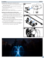
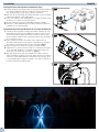
Installing the Airmax LED Light Set on a Round Float. (Fig. 5)
1) To attach the light, clip the light into the inner mounting positions on the float
and use the vertical tension screw to secure the light into place. Continue
until all lights are attached.
2) After attaching the Airmax LED Light Set to the float, connect the quick
disconnect end to the power cord.
3) Attach the light set power cord strain relief on to one of the loops underneath
the float mount ring.
4) Adjust the lights to point in the desired direction.
5) Connect the light set’s power cord into the control panel or other GFCI outlet.
Installing the Airmax LED Light Set on an ISP Float System
1) First, attach one light set mounting bracket on the left side rail of one float
(the AIRMAX logo on the float will be facing you), making sure that the
mounting bracket is positioned between the two float support clamps. Secure
the light set mounting bracket with the two vertical tension screws.
2) Next, install a 3-light set on the holders (with the quick disconnect pointing
toward the fountain) by clipping the light clamp over the holder and securing
in place with a vertical tension screw. (Fig. 6)
3) Repeat for each of the remaining light assemblies.
4) Install the LakeSeries Light Set Junction Box by removing one of the intake
assembly T-Knobs and placing the mounting bracket over the threaded stud.
Secure in place with the T-Knob. (Fig. 7)
5) After completing the fountain assembly procedure, connect each light
assembly to the junction box quick disconnects, and connect the light power
cord to the junction box. Secure the power cord to the unit by clipping the
strain relief to the upper D-ring using the supplied carabiner.
1. Installation
Fig. 5
ENGLISH
Fig. 6
Fig. 7
REVISIONS
ZONE
REV.
DESCRIPTION
DATE
APPROVED
A
1/18/2019
A
DO NOT SCALE DRAWING
653276-R_Junction_Box-12_Light_Set
SHEET 2 OF 2
UNLESS OTHERWISE SPECIFIED:
SCALE: 1:1
WEIGHT:
REV
DWG. NO.
C
SIZE
TITLE:
NAME
DATE
COMMENTS:
Q.A.
MFG APPR.
ENG APPR.
CHECKED
DRAWN
FINISH
MATERIAL
INTERPRET GEOMETRIC
TOLERANCING PER:
DIMENSIONS ARE IN INCHES
TOLERANCES:
ANGULAR: MACH
1.0 BEND
TWO PLACE DECIMAL
0.010
THREE PLACE DECIMAL
0.005
PROPRIETARY AND CONFIDENTIAL
THE INFORMATION CONTAINED IN THIS
DRAWING IS THE SOLE PROPERTY OF
THE POND GUY INC. ANY
REPRODUCTION IN PART OR AS A WHOLE
WITHOUT THE WRITTEN PERMISSION OF
THE POND GUY INC. IS
PROHIBITED.
A A
B B
C C
D D
4
4
3
3
2
2
1
1
3

A) Maintenance
1) Disconnect ALL power from the fountain and lights before attempting any maintenance.
2) Periodically clean light set lens with a non-abrasive brush and cleaner. We recommend Airmax D-Scale (#530298)
B) Winter Removal & Storage
1) Remove the fountain and lights from the pond before ice begins to form.
2) This is the perfect time to clean or power wash any debris on the unit before storing.
3) It is recommended to disconnect lights from fountain and store in an area above freezing temperatures.
C) Spring Installation Inspection
1) Before re-installing the fountain and lights in the spring, check the condition of the power cord and quick disconnect. Replace any o-rings that
may be worn.
3. Maintenance & Winter Storage
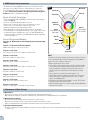
The Airmax Color-Changing RGBW LED Light Set is run by a wireless remote
with a range of up to 200ft. The wireless remote allows you to change the
color, dim/brighten the lights, control flash/fade speed and run up to 9 preset
programs. Your wireless remote has already been paired for your light set
on Zone 1. Requires: 2 AAA Batteries(Included).
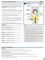
Basic Control Functions
• Press and Hold Master ON or ZONE ON for several seconds to turn all lights to
white mode (Fig. 6)
• Touch the color ring to adjustment lights to any color.
• While in white or solid color mode, use the speed buttons to change
the tone from cool to warm white or vibrant to pastel colors.
• Change the brightness by using the brightness slider.
• Adjust flash/fade speed for any preset program using the speed buttons.
• If controlling light sets for multiple fountains (up to 4) on a single remote, follow
the pairing procedure to add light sets to zones 1-4. MASTER ON will allow
control of ALL light sets simultaneously. ZONE ON buttons will allow individual
control of EACH light set.
Preset Programs/Modes
Press the “M” Mode button to scroll through the pre-programmed light
settings:
Program 1 - Color Flash and Freeze Sequences
Multiple flash and freeze sequences of all colors.
Program 2 - Color Fades
Red, orange, yellow, green, blue, and pink one after the other.
Program 3 - Color Fades
Green, blue, and pink one after the other.
Program 4 - Color Fades
Green, blue, purple, and pink one after the other.
Program 5 - Color Fades
Red, orange, yellow, green, pink, and blue one after the other.
Program 6 - Color Fades
Red, white, and blue one after the other.
Program 7 - Color Fades
White, pink, and blue one after the other.
Program 8 - Color Fades
White, green, blue, and red one after the other.
Program 9 - Color Fades
Blue, green, yellow, pink, red, and purple one after the other.
2. RGBW Remote Control Instructions
Fig. 6
NOTE:
Your wireless remote has aleady been paired for your light set on Zone 1.
In the event that your light set becomes unpaired or to link additional
lights to the remote, follow the steps below.
Linking new lights to the remote control:
1. Ensure that you have new batteries in your remote and that the light
set you wish to pair is within the 200’ working range of the remote
control. Depending on conditions, you may have to decrease the
distance between the lights and the remote during the re-paring
process.
2. Choose which zone you want to assign the lights (1 to 4)
3. Switch off the main power supply of the lights in the selected zone
with the main switch or pull the plug from the socket. For digital
timers, turn to MANUAL OFF.
4. Now switch on the lights again and within 3 seconds, TAP Zone On
button three times on the remote control.
5. When the link operation is successful, the lights will flash GREEN two
times then reset to RED.
Color Ring
Brightness
Indicator
Speed -
(also adjusts to
warm tone)
Zone On
Zone Off
Zones
Speed +
(also adjusts
to cool tone)
Modes
(Programs)
Indicator
Master On Master Off
4

REVISIONS
ZONE
REV.
DESCRIPTION
DATE
APPROVED
A
1/18/2019
A
DO NOT SCALE DRAWING
653275-R_Junction_Box-9_Light_Set
SHEET 1 OF 1
UNLESS OTHERWISE SPECIFIED:
SCALE: 1:2
WEIGHT:
REV
DWG. NO.
C
SIZE
TITLE:
NAME
DATE
COMMENTS:
Q.A.
MFG APPR.
ENG APPR.
CHECKED
DRAWN
FINISH
MATERIAL
INTERPRET GEOMETRIC
TOLERANCING PER:
DIMENSIONS ARE IN INCHES
TOLERANCES:
ANGULAR: MACH
1.0 BEND
TWO PLACE DECIMAL
0.010
THREE PLACE DECIMAL
0.005
PROPRIETARY AND CONFIDENTIAL
THE INFORMATION CONTAINED IN THIS
DRAWING IS THE SOLE PROPERTY OF
THE POND GUY INC. ANY
REPRODUCTION IN PART OR AS A WHOLE
WITHOUT THE WRITTEN PERMISSION OF
THE POND GUY INC. IS
PROHIBITED.
A A
B B
C C
D D
4
4
3
3
2
2
1
1
REVISIONS
ZONE
REV.
DESCRIPTION
DATE
APPROVED
A
1/18/2019
A
DO NOT SCALE DRAWING
653276-R_Junction_Box-12_Light_Set
SHEET 1 OF 1
UNLESS OTHERWISE SPECIFIED:
SCALE: 1:2
WEIGHT:
REV
DWG. NO.
C
SIZE
TITLE:
NAME
DATE
COMMENTS:
Q.A.
MFG APPR.
ENG APPR.
CHECKED
DRAWN
FINISH
MATERIAL
INTERPRET GEOMETRIC
TOLERANCING PER:
DIMENSIONS ARE IN INCHES
TOLERANCES:
ANGULAR: MACH
1.0 BEND
TWO PLACE DECIMAL
0.010
THREE PLACE DECIMAL
0.005
PROPRIETARY AND CONFIDENTIAL
THE INFORMATION CONTAINED IN THIS
DRAWING IS THE SOLE PROPERTY OF
THE POND GUY INC. ANY
REPRODUCTION IN PART OR AS A WHOLE
WITHOUT THE WRITTEN PERMISSION OF
THE POND GUY INC. IS
PROHIBITED.
A A
B B
C C
D D
4
4
3
3
2
2
1
1
4. Troubleshooting
5. Replacement Parts
IF ONE OR MORE (NOT ALL) LIGHTS DIM
ISSUE CORRECTION
Water in fixtures Contact Airmax or local dealer for repair/replacement
LED bulb driver failed Contact Airmax or local dealer for repair/replacement
IF LIGHTS FLICKER
ISSUE CORRECTION
Water in fixtures Contact Airmax or local dealer for repair/replacement
Voltage not high enough for starting Make sure voltage at receptacle is 120V+-5%
LED bulb driver failed Contact Airmax or local dealer for repair/replacement
IF LIGHTS TURN ON AND OFF INTERMITTENTLY
ISSUE CORRECTION
Water in fixtures Contact Airmax or local dealer for repair/replacement
LED bulb driver failed Contact Airmax or local dealer for repair/replacement
IF ALL LIGHTS OFF
ISSUE CORRECTION
GFCI tripped Reset GFCI
Power cord cut Repair or replace power cord
Water in fixtures Contact Airmax or local dealer for repair/replacement
Voltage not high enough for starting Make sure voltage at receptacle is 120V+-5%
Timer not running Verify timer is keeping time, replace timer if not
Timer not set to AUTO Press MANUAL button to move indicator to AUTO.
IF ONE OR MORE (NOT ALL) LIGHTS OFF
ISSUE CORRECTION
Water in fixtures
Contact Airmax or local dealer for repair/replacementLED bulb driver failed
LED bulb failed
IF LIGHTS DIM
ISSUE CORRECTION
Voltage not high enough for starting Make sure voltage at receptacle is 120V+-5%
Lens might be dirty Clean with a non-abrasive brush or cleaner
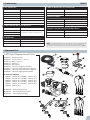
1. #651307 – Mounting Clamp
2. #651325 – Tension Screw, ¼ - 20 x 1 ¼”
3. #651722 – Bolt, ¼ - 20 x 1 ¼”
4. #651723 – Washer, ¼”
5. #651308 – Band Clamp
6. #653224 – LakeSeries 3 Light Set Assembly
7. #653275 – LakeSeries Junction Box for 9 Light Set
8. #653276 – LakeSeries Junction Box for 12 Light Set
9. #653287 – LakeSeries Light Bracket Assembly
10. Power Cord Options
#652646 – 100 feet, 16/3
#652647 – 150 feet, 16/3
#652648 – 200 feet, 16/3
#652649 – 250 feet, 16/3
#652667 – 300 feet, 16/3
#652668 – 350 feet, 16/3
11. #651060 – Strain Relief (16 gauge)
12. #651357 – Power Cord End Cap, Female
13. # 651163 – Female End Cap, O-Ring
LED Light Replacement Parts
1
3
2
4
5
11
12
13
10
NOTE: Pre-Programmed light modes can cause lights to dim, flicker, and fade in and out. When trouble
shooting, please ensure you are in the basic ON mode by turning the unit off with the “MASTER OFF”
button, then press and hold “MASTER ON” for several seconds to turn all lights to white mode. (Fig. 6)
ENGLISH
6
#652669 – 400 feet, 16/3
#651560 – 450 feet, 16/3
#651561 – 500 feet, 16/3
#651652 – 550 feet, 16/3
#651563 – 600 feet, 16/3
7
8
9
5

Installing the Airmax LED Light Set on a Round float. (Fig.5)
1) Pour fixer la lumière, fixez la lumière dans les positions de montage intérieures
sur le flotteur et utilisez la vis de tension verticale pour fixer la lumière en
place. Continuez jusqu’à ce que toutes les lumières soient fixées.
2) Après avoir fixé le jeu d’éclairage LED Airmax au flotteur, connectez l’extrémité
à déconnexion rapide au cordon d’alimentation.
3) Fixez le serre-câble du cordon d’alimentation de l’ensemble d’éclairage à l’une
des boucles sous l’anneau de montage du flotteur.
4) Ajustez les lumières pour qu’elles pointent dans la direction souhaitée.
5) Connectez le cordon d’alimentation de l’ensemble d’éclairage au panneau de
commande ou à une autre prise GFCI.
Installation du jeu d’éclairage LED Airmax sur un système de flotteur ISP
1) Tout d’abord, fixez un support de montage d’ensemble d’éclairage sur le rail
latéral gauche d’un flotteur (le logo AIRMAX sur le flotteur sera face à vous),
en vous assurant que le support de montage est positionné entre les deux
pinces de support de flotteur. Fixez le support de montage du jeu d’éclairage
avec les deux vis à oreilles.
2) Ensuite, installez un ensemble de 3 lumières sur les supports (avec la
déconnexion rapide pointant vers la fontaine) en clipsant la pince de lumière
sur le support et en la fixant en place avec une vis à oreilles. (Fig. 6)
3) Répétez l’opération pour chacun des ensembles d’éclairage restants.
4) Installez la boîte de jonction LakeSeries Light Set en retirant l’un des boutons
en T de l’ensemble d’admission et en plaçant le support de montage sur le
goujon fileté. Fixez en place avec le bouton en T. (Fig. 7)
5) Après avoir terminé la procédure d’assemblage de la fontaine, connectez
chaque assemblage d’éclairage aux raccords rapides de la boîte de jonction et
connectez le cordon d’alimentation de l’éclairage à la boîte de jonction. Fixez
le cordon d’alimentation à l’appareil en clipsant le serre-câble sur l’anneau en
D supérieur à l’aide du mousqueton fourni.
1. Installation
Fig. 5
FRANÇIAS
Fig. 6
Fig. 7
REVISIONS
ZONE
REV.
DESCRIPTION
DATE
APPROVED
A
1/18/2019
A
DO NOT SCALE DRAWING
653276-R_Junction_Box-12_Light_Set
SHEET 2 OF 2
UNLESS OTHERWISE SPECIFIED:
SCALE: 1:1
WEIGHT:
REV
DWG. NO.
C
SIZE
TITLE:
NAME
DATE
COMMENTS:
Q.A.
MFG APPR.
ENG APPR.
CHECKED
DRAWN
FINISH
MATERIAL
INTERPRET GEOMETRIC
TOLERANCING PER:
DIMENSIONS ARE IN INCHES
TOLERANCES:
ANGULAR: MACH
1.0 BEND
TWO PLACE DECIMAL
0.010
THREE PLACE DECIMAL
0.005
PROPRIETARY AND CONFIDENTIAL
THE INFORMATION CONTAINED IN THIS
DRAWING IS THE SOLE PROPERTY OF
THE POND GUY INC. ANY
REPRODUCTION IN PART OR AS A WHOLE
WITHOUT THE WRITTEN PERMISSION OF
THE POND GUY INC. IS
PROHIBITED.
A A
B B
C C
D D
4
4
3
3
2
2
1
1
6

2. Instructions de télécommande RGBW
Le système de lumière LED RGBW modifiant les couleurs Airmax est exécuté
par une télécommande sans fil pouvant atteindre 200 pieds. La télécommande
sans fil vous permet de changer de couleur, de sombrer / allumer les lumières,
de contrôler la vitesse du flash et d’exécuter jusqu’à 9 programmes préréglés.
Votre télécommande sans fil a déjà été jumelée pour votre éclairage
réglé sur la Zone 1. Nécessite: 2 piles AAA (incluses).
Fonctions de contrôle de base
• Appuyez et maintenez la touche principal ON ou zone ON enfoncée pendant
plusieurs secondes pour allumer toutes les lumières en mode blanc. (Fig. 6)
• Touchez la bague de couleur sur les lumières de réglage sur n’importe quelle
couleur.
• En mode couleur blanc ou uni, utilisez les boutons de vitesse pour changer
le ton du blanc froid au blanc chaud ou des couleurs vives aux pastels.
• Changez la luminosité en utilisant la bague de glissement.
• Réglez la vitesse du flash/ décolorer pour tout programme préréglé à l’aide
des boutons de vitesse.
• Si vous contrôlez des ensembles d’éclairage pour plusieurs fontaines (jusqu’à
4) sur une seule télécommande, suivez la procédure d’appariement pour
ajouter des ensembles d’éclairage aux zones 1-4. MASTER ON permettra le
contrôle de TOUS les jeux de lumières simultanément. Les boutons ZONE ON
permettront un contrôle individuel de CHAQUE jeu de lumière.
Programme/Mode Prédéfinis
Appuyez sur le bouton “M” pour faire défiler les réglages de lumière
préprogrammés:
Programme 1- Flash couleur et pause: Plusieurs séquences de flash et de
pause de toutes les couleurs.
Programme 2 - Décoloration de la couleurr: Rouge, orange, jaune, vert,
bleu et rose les uns après les autres.
Programme 3 - Décoloration de la couleur: Vert, bleu et rose l’un après
l’autre.
Programme 4 - Décoloration de la couleur: Vert, bleu, violet et rose l’un
après l’autre.
Programme 5 - Décoloration de la couleur: Rouge, orange, jaune, vert,
rose et bleu les uns après les autres.
Programme 6 - Décoloration de la couleur: Rouge, blanc et bleu l’un
après l’autre.
Programme 7 - Décoloration de la couleur: Blanc, rose et bleu l’un après
l’autre.
Programme 8 - Décoloration de la couleur: Blanc, vert, bleu et rouge l’un
après l’autre.
Programme 9 - Décoloration de la couleur: Bleu, vert, jaune, rose, rouge
et violet l’un après l’autre.
Bague de
Couleur
Indicateur de
Luminosité
Principal Sur
Vitesse -
(s’ajuste également
au ton chaud)
Sur Zone
Éteindre Zone
Zones
Principal
Éteindre
Vitesse +
(s’ajuste
également
au ton froid)
Modes (Programmes)
Indicateur
Fig. 6
NOTE:
Votre télécommande sans fil a déjà été jumelée pour votre éclairage réglé sur la
Zone 1.
Si vous ne parvenez pas à allumer votre éclairage ou si vous voulez lier des
lumières supplémentaires à la télécommande, suivez les étapes ci-dessous.
Lier de nouvelles lumières à la télécommande:
1. Assurez-vous que vous avez de nouvelles piles dans votre télécommande et
que le jeu de lumières que vous souhaitez coupler se trouve dans la plage de
fonctionnement de 200 pieds de la télécommande. Selon les conditions, vous
devrez peut-être réduire la distance entre les lumières et la télécommande
pendant le processus de recomposition.
2. Choisissez la zone à laquelle vous souhaitez attribuer les lumières (1 à 4)
3. Coupez l’alimentation principale des lampes de la zone sélectionnée à l’aide
de l’interrupteur principal ou retirez la fiche de la prise. Pour les minuteries
numériques, sélectionnez MANUAL OFF
4. Maintenant, allumez à nouveau les lumières et dans les 3 secondes, appuyez
trois fois sur le bouton TAP Zone On de la télécommande.
5. Lorsque l’opération de liaison est réussie, les voyants clignotent en VERT
deux fois puis se remettent au ROUGE.
A) Maintenance
1) Coupez toutes les alimentations de la fontaine et les lumières avant tout entretien.
2) Nettoyez régulièrement l’écran d’admission fontaine de débris, d’algues et / ou de mauvaises herbes aquatiques.
3) Nettoyez régulièrement la lentille de jeu de la lumière avec une brosse non-abrasive et plus propre.
B) Hiver Enlèvement et stockage
1) Retirer la fontaine et les lumières de l’étang avant que la glace commence à se former.
2) Ce est le moment idéal pour nettoyer ou de pouvoir laver les débris de l’appareil avant de le ranger.
3) Il est recommandé de débrancher les feux de fontaine et entreposer dans un endroit au-dessus des températures de congélation.
C) Inspection Printemps d’installation
1) Avant de réinstaller la fontaine et les lumières au printemps, vérifier l’état du cordon d’alimentation, connecteurs à déconnexion rapide et
remplacer les joints toriques qui peuvent être cassées.
3. Entretien et stockage hivernal
FRANÇIAS
7

5. Pièces de Rechange
REVISIONS
ZONE
REV.
DESCRIPTION
DATE
APPROVED
A
1/18/2019
A
DO NOT SCALE DRAWING
653275-R_Junction_Box-9_Light_Set
SHEET 1 OF 1
UNLESS OTHERWISE SPECIFIED:
SCALE: 1:2
WEIGHT:
REV
DWG. NO.
C
SIZE
TITLE:
NAME
DATE
COMMENTS:
Q.A.
MFG APPR.
ENG APPR.
CHECKED
DRAWN
FINISH
MATERIAL
INTERPRET GEOMETRIC
TOLERANCING PER:
DIMENSIONS ARE IN INCHES
TOLERANCES:
ANGULAR: MACH
1.0 BEND
TWO PLACE DECIMAL
0.010
THREE PLACE DECIMAL
0.005
PROPRIETARY AND CONFIDENTIAL
THE INFORMATION CONTAINED IN THIS
DRAWING IS THE SOLE PROPERTY OF
THE POND GUY INC. ANY
REPRODUCTION IN PART OR AS A WHOLE
WITHOUT THE WRITTEN PERMISSION OF
THE POND GUY INC. IS
PROHIBITED.
A A
B B
C C
D D
4
4
3
3
2
2
1
1
REVISIONS
ZONE
REV.
DESCRIPTION
DATE
APPROVED
A
1/18/2019
A
DO NOT SCALE DRAWING
653276-R_Junction_Box-12_Light_Set
SHEET 1 OF 1
UNLESS OTHERWISE SPECIFIED:
SCALE: 1:2
WEIGHT:
REV
DWG. NO.
C
SIZE
TITLE:
NAME
DATE
COMMENTS:
Q.A.
MFG APPR.
ENG APPR.
CHECKED
DRAWN
FINISH
MATERIAL
INTERPRET GEOMETRIC
TOLERANCING PER:
DIMENSIONS ARE IN INCHES
TOLERANCES:
ANGULAR: MACH
1.0 BEND
TWO PLACE DECIMAL
0.010
THREE PLACE DECIMAL
0.005
PROPRIETARY AND CONFIDENTIAL
THE INFORMATION CONTAINED IN THIS
DRAWING IS THE SOLE PROPERTY OF
THE POND GUY INC. ANY
REPRODUCTION IN PART OR AS A WHOLE
WITHOUT THE WRITTEN PERMISSION OF
THE POND GUY INC. IS
PROHIBITED.
A A
B B
C C
D D
4
4
3
3
2
2
1
1
1
3
2
4
5
11
12
13
10
6
7
8
9
Pièces de rechange LED
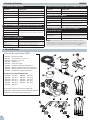
#652669 – 400’, 16/3
#651560 – 450’, 16/3
#651561 – 500’, 16/3
#651652 – 550’, 16/3
#651563 – 600’, 16/3
1. #651307 – Pince de montage
2. #651325 – Vis de tension, ¼ - 20 x 1 ¼”
3. #651722 – Boulon, ¼ - 20 x 1 ¼”
4. #651723 – Rondelle, ¼”
5. #651308 – Collier de serrage
6. #653224 – Ensemble d’éclairage LakeSeries 3
7. #653275 – Boîte de jonction pour jeu de 9 lumières
8. #653276 – Boîte de jonction pour jeu de 12 lumières
9. #653287 – Ensemble de support de lumière
10. Options de cordon d’alimentation
#652646 – 100’, 16/3
#652647 – 150’, 16/3
#652648 – 200’, 16/3
#652649 – 250’, 16/3
#652667 – 300’, 16/3
#652668 – 350’, 16/3
11. #651060 – Décharge de traction (calibre 16)
12. #651357 – Embout de cordon d’alimentation, femelle
13. # 651163 – Embout femelle, joint torique
4. Résolution de Problème
SI UN OU PLUSIEURS (PAS TOUS) LES LUMIÈRES TAMISÉES
QUESTION CORRECTION
Eau sur les appareils Contactez Airmax ou revendeur local pour réparation / remplacement
LED bulb driver failed Contactez Airmax ou revendeur local pour réparation / remplacement
SI SCINTILLEMENT LUMIÈRE
QUESTION CORRECTION
Eau sur les appareils Contactez Airmax ou revendeur local pour réparation / remplacement
Tension pas assez élevé pour un
démarrage Assurez-vous que la tension au réceptacle est 120V + -5%
Pilote d’ampoule LED échoué Contactez Airmax ou revendeur local pour réparation / remplacement
SI LES LUMIÈRES ALLUMENT ET SE ÉTEIGNENT
PAR INTERMITTENCE
QUESTION CORRECTION
Eau sur les appareils Contactez Airmax ou revendeur local pour réparation / remplacement
Pilote d’ampoule LED échoué Contactez Airmax ou revendeur local pour réparation / remplacement
SI TOUS LES VOYANTS HORS
QUESTION CORRECTION
GFCI déclenché Réinitialiser GFCI
Cordon d’alimentation Cut Réparer ou remplacer le cordon d’alimentation
Eau sur les appareils Contactez Airmax ou revendeur local pour réparation / remplacement
Tension pas assez élevé pour un
démarrage Assurez-vous que la tension au réceptacle est 120V + -5%
Minuterie ne fonctionne pas Vérifiez la minuterie est de garder le temps, remplacer minuterie sinon
La minuterie n’est pas réglée sur AUTO Appuyez sur le bouton MANUEL pour déplacer l’indicateur sur AUTO
SI UN OU PLUSIEURS (MAIS PAS TOUS) SE ALLUME OFF
QUESTION CORRECTION
Eau sur les appareils
Contactez Airmax ou revendeur local pour réparation / remplacementPilote d’ampoule LED échoué
LED Bulb failed
SI LUMIÈRES SE ÉTEIGNENT
QUESTION CORRECTION
Tension pas assez élevé pour un
démarrage Assurez-vous que la tension au réceptacle est 120V + -5%
Objectif peut-être sale Nettoyer avec une brosse ou un nettoyant non abrasif
NOTER: Les modes de lumière pré-programmés peuvent provoquer des lumières qui s’allument,
scintillent et disparaissent. Lors de la prise de décision, assurez-vous que vous êtes en mode “SUR” basique
en éteignant l’appareil avec le bouton “PRINCIPAL ÉTEINDRE”, puis maintenez la touche PRINCIPAL SUR
enfoncée pendant plusieurs secondes pour allumer toutes les lumières en mode blanc. (Fig. 6)
FRANÇIAS
8

Airmax, Inc.
Airmax LED Light Sets
Limited Warranty
Airmax, Inc. warrants to the original purchaser (the end user) of any Airmax LED Light Sets manufactured
by Airmax, Inc. that any component which proves to be defective in materials or workmanship, as
determined by the factory within 3 years from the original purchased date, will be repaired or replaced at
no charge with a new or remanufactured part, and returned freight prepaid. The end user shall assume all
the responsibility and expense for removal, packaging, and freight to ship to Airmax, Inc. to determine the
warranty claim and for all reinstallation expenses.
The warranty is void in cases where damage results from: improper installation, improper electrical
connection, improper voltage, alteration, lightning, careless handling, misuse, abuse, disassembly of unit
or failure to follow maintenance or operating instructions. Modication or repair by an unauthorized repair
facility will void the warranty.
In no case will Airmax, Inc. or its dealers accept responsibility for any costs incurred by the user during
installation, removal, inspection, evaluation, repair, parts replacement, or for return freight. Nor will any
liability be accepted for loss of use, loss of prots, loss of goodwill, for consequential damage, or for personal
injuries to the purchaser or any person.
In the event of problems believed to be covered under warranty, it will be necessary to notify the dealer
who will try to help resolve the problem and who may contact the factory for additional assistance. If it is
concluded that there may be a defect which may be covered under warranty, it will be necessary to get a
Return Material Authorization (RMA) from the dealer before shipment. Freight collect shipments will not
be accepted by the factory on warranties or repairs.
The product or part(s) must be returned freight prepaid, to the factory, as directed, and in its original
packaging or in a container which will prevent damage. Parts returned under warranty and damaged during
shipping will not be covered under warranty for the shipping damage. If the factory evaluation of the
returned goods concludes that the failure is due to defects in materials or workmanship, the part or parts
in question will be replaced under warranty with new parts, remanufactured parts, or will be repaired; at
the factory’s option. The warranty period for all parts supplied under warranty will terminate at the end of
the original product’s warranty. All warranty shipments from the factory will be shipped freight prepaid.
Warranty registration is HIGHLY recommended.
No implied warranties of any kind are made by Airmax, Inc. for its products, and no other warranties,
whether expressed or implied, including implied warranties of merchantability and tness for a
particular purpose, shall apply. Should an Airmax, Inc. product prove to be defective in materials or
workmanship, the retail purchaser’s sole remedy shall be repair or replacement of the product as expressly
provided above.
The manufacturer’s warranty will begin from the dealer’s original purchase date if the product is not
registered. To register a product, you are required to ll out the warranty registration form at airmaxeco.
com/warranty. Warranty registration must be submitted directly to Airmax within 30 days of the end-users
purchase date.
REVISIONS
ZONE
REV.
DESCRIPTION
DATE
APPROVED
A
1/18/2019
A
DO NOT SCALE DRAWING
653275-R_Junction_Box-9_Light_Set
SHEET 1 OF 1
UNLESS OTHERWISE SPECIFIED:
SCALE: 1:2
WEIGHT:
REV
DWG. NO.
C
SIZE
TITLE:
NAME
DATE
COMMENTS:
Q.A.
MFG APPR.
ENG APPR.
CHECKED
DRAWN
FINISH
MATERIAL
INTERPRET GEOMETRIC
TOLERANCING PER:
DIMENSIONS ARE IN INCHES
TOLERANCES:
ANGULAR: MACH
1.0 BEND
TWO PLACE DECIMAL
0.010
THREE PLACE DECIMAL
0.005
PROPRIETARY AND CONFIDENTIAL
THE INFORMATION CONTAINED IN THIS
DRAWING IS THE SOLE PROPERTY OF
THE POND GUY INC. ANY
REPRODUCTION IN PART OR AS A WHOLE
WITHOUT THE WRITTEN PERMISSION OF
THE POND GUY INC. IS
PROHIBITED.
A A
B B
C C
D D
4
4
3
3
2
2
1
1
REVISIONS
ZONE
REV.
DESCRIPTION
DATE
APPROVED
A
1/18/2019
A
DO NOT SCALE DRAWING
653276-R_Junction_Box-12_Light_Set
SHEET 1 OF 1
UNLESS OTHERWISE SPECIFIED:
SCALE: 1:2
WEIGHT:
REV
DWG. NO.
C
SIZE
TITLE:
NAME
DATE
COMMENTS:
Q.A.
MFG APPR.
ENG APPR.
CHECKED
DRAWN
FINISH
MATERIAL
INTERPRET GEOMETRIC
TOLERANCING PER:
DIMENSIONS ARE IN INCHES
TOLERANCES:
ANGULAR: MACH
1.0 BEND
TWO PLACE DECIMAL
0.010
THREE PLACE DECIMAL
0.005
PROPRIETARY AND CONFIDENTIAL
THE INFORMATION CONTAINED IN THIS
DRAWING IS THE SOLE PROPERTY OF
THE POND GUY INC. ANY
REPRODUCTION IN PART OR AS A WHOLE
WITHOUT THE WRITTEN PERMISSION OF
THE POND GUY INC. IS
PROHIBITED.
A A
B B
C C
D D
4
4
3
3
2
2
1
1
9

Notes
Call your local Airmax Dealer with questions or to order parts.
10

Notes
Call your local Airmax Dealer with questions or to order parts. 11

#652043 V4
Airmax, Inc.
15425 Chets Way Street
Armada, MI 48005
(866) 4-AIRMAX
airmaxeco.com
-
 1
1
-
 2
2
-
 3
3
-
 4
4
-
 5
5
-
 6
6
-
 7
7
-
 8
8
-
 9
9
-
 10
10
-
 11
11
-
 12
12


