
PG 690, PG 690 RC, PG 830, PG 830 RC
EN Operator's manual 2-52
DE Bedienungsanweisung 53-103
FR Manuel d'utilisation 104-154
NL Gebruiksaanwijzing 155-204

Contents
Introduction..................................................................... 2
Safety..............................................................................9
Operation...................................................................... 15
Maintenance................................................................. 33
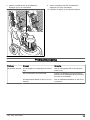
Troubleshooting............................................................ 38
Transportation, storage and disposal........................... 42
Technical data.............................................................. 46
Declaration of Conformity............................................. 49
Declaration of Conformity............................................. 51
Introduction
Product description
The product is a floor grinder for surfaces of different
hardness.
The models PG 690 RC, PG 830 RC can be operated
with a remote control.
Intended use
The product is used to grind surfaces of materials with
different hardness such as natural stone, terazzo and
concrete. Also use the product to grind cover materials
such as epoxy and glue. The finish of the surface can
be rough or smooth. The product can be used for dry
grinding and wet grinding. Do not use the product for
other tasks.
The product is used in commercial operations by
professional operators.
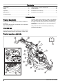
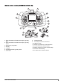
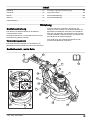
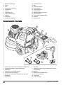
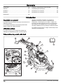
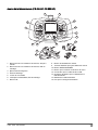
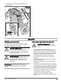
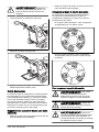
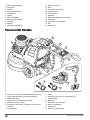
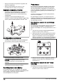
Product overview, right side
17
18
19
20
16
5
23
4
6
14
78
1
12
9
13
22
21
10
15
11
10
21163 - 005 - 09.12.2022

1. Operator's manual
2. Handlebar
3. Handle
4. Headlight (accessory)
5. Electrical enclosure
6. Lifting eye
7. Grinding head motor
8. Grinding disc motor
9. Support wheel
10. Grinding head
11. Weight lock
12. Locking pin for wheel
13. Wheel
14. Weights (accessory)
15. Weight holder
16. Weight bracket
17. Grinding disc
18. Diamond tool (accessory)
19. Tool plate
20. Connection for dust extractor
21. Cover
22. Dust skirt
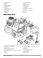
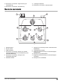
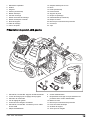
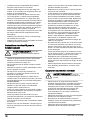
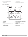
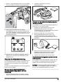
Product overview, left side
3
2
13
12
4
14
18
17
16
7
9
1
15
10
8
5
6
11
1. PG 690 RC, PG 830 RC: Remote control holder
2. Lock lever for handle adjustment
3. Control panel
4. Screws for handlebar adjustment
5. Battery charger connector
6. PG 690 RC, PG 830 RC: Connector for the CAN bus
cable
7. Rating plate
8. Power cord
9. Suspension device for dust extractor hose and
power cord
10. Wheel motor
11. Connection for dust extractor
12. Door to electrical box
13. Support frame
14. Holes for straps
1163 - 005 - 09.12.2022 3

15. PG 690 RC, PG 830 RC: Remote control harness
16. PG 690 RC, PG 830 RC: Remote control
17. 1-phase charge cable
18. PG 690 RC, PG 830 RC: CAN bus cable
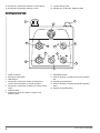
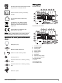
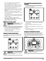
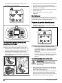
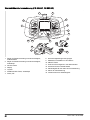
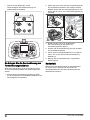
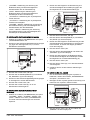
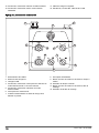
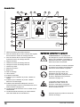
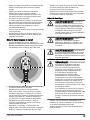
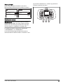
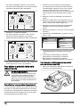
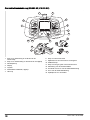
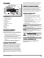
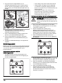
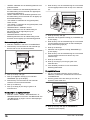
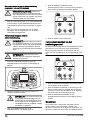
Control panel overview
2
3
1
4
6
11
9
8
7
10
12 5
1. Cable connection
2. Emergency stop button
3. USB charger
4. PG 690 RC, PG 830 RC: Switch for selection of
remote control operation or manual operation
5. PG 690 RC, PG 830 RC: Indicator for remote control
mode
6. ON/OFF switch
7. Indicator for power and state of charge of the
product battery
8. STOP/RUN switch
9. Knob for direction of rotation and speed, grinding
disc
10. Indicator for grinding disc
11. Knob for direction of rotation and speed, grinding
head
12. Indicator for grinding head
41163 - 005 - 09.12.2022

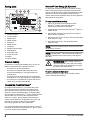
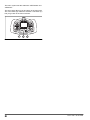
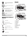
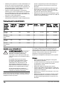
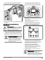
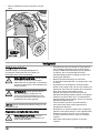
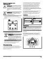
Remote control overview (PG 690 RC, PG 830 RC)
6
1
12
11
7
8
9
10
13
34
5
2
14
15
1. Knob for direction of rotation and speed, grinding
disc
2. Knob for direction of rotation and speed, grinding
head
3. Emergency stop button
4. Display
5. Joystick
6. STOP/RUN switch, grinding head
7. OK button
8. Speed limit knob
9. Arrow keys to scroll in the menus
10. ON/OFF button
11. Button to go back in the menu structure
12. Connector for the CAN bus cable
13. Battery charger for remote control battery
14. Remote control battery
15. Charger port for battery charger
1163 - 005 - 09.12.2022 5

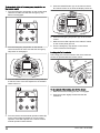
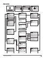
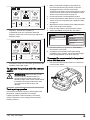
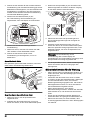
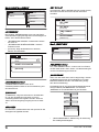
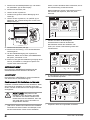
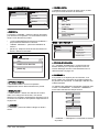
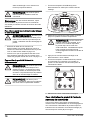
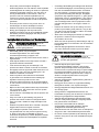
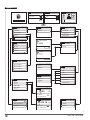
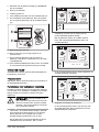
Display overview
0
SPEED
0
12:45Jan 05
0
POWER
REV FWD
OK
0
SPEED
0
POWER
REV FWD
OFF
17 16 15 14 13 12 11
3
2
5
6
9
10
1
2
8
7
6
5
4
3
1. Battery level of the remote control
2. Counterclockwise direction of rotation on related
grinding motor
3. Clockwise direction of rotation on related grinding
motor
4. Grinding discs
5. Speed indication on related grinding motor
6. Load indication on related grinding motor
7. Product speed indication
8. Functions menu
9. OK button
10. Grinding head
11. Time and date
12. Servicing indication
13. Product battery indication: the battery charges
14. Product battery indication: the battery is missing or
damaged
15. Warning indicator. Refer to
Error and warning
messages on the remote control on page 40
.
16. The remote control is operated with a CAN bus cable
connected
17. The remote control is operated by radio
communication without a CAN bus cable connected
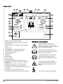
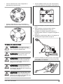
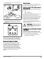
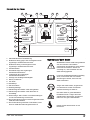
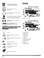
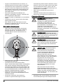
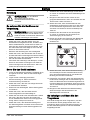
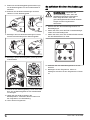
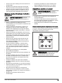
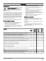
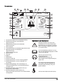
Symbols on the product
WARNING: This product can be
dangerous and cause serious injury or
death to the operator or others. Be careful
and use the product correctly.
Read the manual carefully and make
sure that you understand the instructions
before you use the product.
Use hearing protection, eye protection
and respiratory protection. Refer to
Personal protective equipment on page
10
.
The dust can cause health problems.
Use an approved respiratory protection.
Always make sure that there is good
airflow.
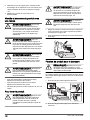
Always lift the product at the lifting eye.
61163 - 005 - 09.12.2022

Use the holes for tie-down straps to attach
the product to a transport vehicle.
Double insulation, battery and battery
charger.
Use and keep battery charger only
indoors.
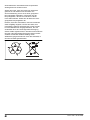
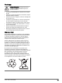
The product is not domestic waste.
Recycle it at an approved disposal
location for electrical and electronic
equipment.
This product is in compliance with
applicable EC directives.
Note: Other symbols/decals on the product refer to
special certification requirements for some markets.
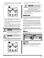
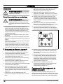
Symbols on the control panel and the remote
control
Emergency stop.
Remote control operation on.
Product on and reset the product.
Grinding head on.
Speed and direction of rotation, grinding
head.
Speed and direction of rotation, grinding
disc.
Maximum speed.
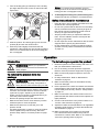
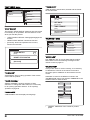
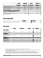
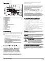
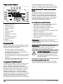
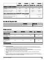
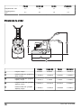
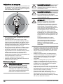
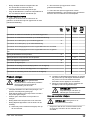
Rating plate
PG 690, PG 830:
10
1 4 5 62 3
11
12
13
7
8
9
PG 690 RC, PG 830 RC:
10
1 4 5 62 3
11
12
13
7
8
9
1. Product number
2. Product weight
3. Rated power
4. Rated voltage
5. Rated current
6. Frequency
7. Enclosure
8. Maximum slope angle
9. Manufacturer/Importer
10. Serial number
11. Model
12. Production year
13. Scannable code
1163 - 005 - 09.12.2022 7

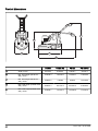
Rating plate
13
11
10
12
21 3 4
6
5
8
9
7
1. Product number
2. Product weight
3. Rated power
4. Rated voltage
5. Enclosure
6. Rated current
7. Frequency
8. Maximum slope angle
9. Manufacturer
10. Scannable code
11. Production year
12. Model
13. Serial number
Product liability
As referred to in the product liability laws, we are not
liable for damages that our product causes if:
• the product is incorrectly repaired.
• the product is repaired with parts that are not
from the manufacturer or not approved by the
manufacturer.
• the product has an accessory that is not from the
manufacturer or not approved by the manufacturer.
• the product is not repaired at an approved service
center or by an approved authority.
Husqvarna Fleet Services™
Husqvarna Fleet Services™ is a cloud solution that
gives the operator an overview of all products that
are connected. This product has a Husqvarna Fleet
Services™ sensor with Bluetooth® Low Energy (BLE).
The Husqvarna Fleet Services™ sensor collects product
data and lets you connect to the Husqvarna Fleet
Services™ system. The Husqvarna Fleet Services™
system reports data such as operation time, servicing
intervals and location of the product. The BLE
technology operates at 2.400–2.4835 GHz.
For more information about Husqvarna Fleet Services™,
download the Husqvarna Fleet Services™ app or speak
to your Husqvarna representative.
Bluetooth® Low Energy (BLE) module
On approved markets the product has a BLE module
that is connected with the Husqvarna Fleet Services™
system. The BLE module collects and transmits product
data that is used in the Husqvarna Fleet Services™
system. Data such as operation time, servicing intervals
and location of the product.
To setup embedded connectivity
1. Set up an account for the Husqvarna Fleet
Services™ system at the web site https://
fleetservices.husqvarna.com/signup.
2. Download the Husqvarna Fleet Services™ app on a
mobile device.
3. Connect the product to a power source to put the
BLE module in operation.
4. Add the product to your account. Use the Husqvarna
Fleet Services™ app.
5. Obey the instructions in the Husqvarna Fleet
Services™ app.
Note: The Fleet enabled mobile device must be near
the product to connect.
Note: The Bluetooth® radio transmission enables on
the first connection to the power source, and stays on
after that.
WARNING: High voltage. There are
unprotected parts in the power unit. Always
disconnect the power plug before you open
the door to the electrical box.
To put the product into flight mode
When the product is in flight mode, the BLE module
stops to transmit product data.
81163 - 005 - 09.12.2022

• Push the battery pack switch to the OFF position.
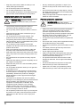
Safety
Safety definitions
Warnings, cautions and notes are used to point out
specially important parts of the manual.
WARNING: Used if there is a risk of
injury or death for the operator or bystanders
if the instructions in the manual are not
obeyed.
CAUTION: Used if there is a risk of
damage to the product, other materials or
the adjacent area if the instructions in the
manual are not obeyed.
Note: Used to give more information that is necessary
in a given situation.
General safety instructions
WARNING: Read the warning
instructions that follow before you use the
product.
• This product is a dangerous tool if you are not
careful or if you use the product incorrectly. This
product can cause serious injury or death to the
operator or others. Before you use the product,
you must read and understand the contents of this
operator’s manual.
• Save all warnings and instructions.
• Comply with all applicable laws and regulations.
• The operator and the employer of the operator must
know and prevent the risks during operation of the
product.
• Do not let a person operate the product unless they
read and understand the contents of the operator's
manual.
• Do not operate the product unless you receive
training before use. Make sure that all operators
receive training.
• Do not let a child operate the product.
• Only let approved persons operate the product.
• The operator is responsible for accidents that occur
to other persons or their property.
• Do not use the product if you are tired, ill, or under
the influence of alcohol, drugs or medicine.
• Always be careful and use your common sense.
• This product produces an electromagnetic field
during operation. This field can under some
circumstances interfere with active or passive
medical implants. To decrease the risk of serious
injury or death, we recommend persons with medical
implants to speak to their physician and the medical
implant manufacturer before operating this product.
1163 - 005 - 09.12.2022 9

• Keep the product clean. Make sure that you can
clearly read signs and decals.
• Do not use the product if it is damaged.
• Do not make modifications to this product.
• Do not operate the product if it is possible that other
persons have made modifications to the product.
Safety instructions for operation
WARNING: Read the warning
instructions that follow before you use the
product.
• Use personal protective equipment. Refer to
Personal protective equipment on page 10
.
• Do not go away from the product when the motor is
on.
• Always disconnect the power cord before you go
away from the product.
• Do not pull the hose of the dust extractor. The
product can fall and cause injury or damage.
• The grinding head must touch the surface when you
start the product. This is not applicable when you do
a check of the ON/OFF switch.
• Do not start the product without the dust skirt
installed. The dust skirt must seal fully between the
product and the floor.
• Keep your feet away from the CAN bus cable and
the power cord to decrease the risk of fall injury.
• Keep away from areas where the product can cause
injury. The product can quickly change position and
hit you.
• If the product does not operate correctly, stop the
motors.
• Make sure that clothing, long hair and jewelry do not
get caught in moving parts.
• Make sure that you are in a safe and stable position
during operation.
• Do not operate the product unless you can get aid if
an accident occurs.
• If vibrations occur in the product or the noise level
from the product is unusually high, stop the product
immediately. Examine the product for damages.
Repair damages or let an approved service agent
do the repair.
• Overexposure to vibration can cause circulatory
damage or nerve damage to persons with decreased
blood circulation. Get medical aid if you have
symptoms of overexposure to vibration. These
symptoms include numbness, loss of feeling,
tingling, pricking, pain, loss of strength, changes
in skin color or condition. These symptoms usually
show in the fingers, hands or wrists.
• Do not park the product on a slope. If you must park
the product on a slope, make sure that the product
cannot move or fall. There is a risk of injury and
damage.
• Be very careful during operation on slopes. The
product is heavy and can cause serious injury if it
falls.
• Do not move the product on steep slopes. Look at
the rating plate on the product for information about
the maximum slope angle.
• Always use approved accessories. Speak to your
dealer for more information.
Personal protective equipment
WARNING: Read the warning
instructions that follow before you use the
product.
• Always use correct personal protective equipment
when you operate the product. The personal
protective equipment does not erase the risk of
injury. The personal protective equipment decreases
the grade of injury if an accident occurs. Let your
dealer help you select the right equipment.
• Use approved eye protection while you operate the
product.
• Do not use loose, heavy and not applicable clothing.
Use clothes that let you move freely.
• Use approved protective gloves that enables a solid
hold.
• Use rubber protective gloves that prevents skin
irritation from wet concrete.
• Use an approved protective helmet.
• Always use approved hearing protection while you
operate the product. Noise for a long period can
cause noise-induced hearing loss.
• The product makes dust and fumes that contain
dangerous chemicals. Use an approved breathing
protection.
• Use boots with steel toe-caps and non-slip soles.
• Make sure that you have a first aid kit near.
• Sparks can occur when you operate the product.
Make sure that you have a fire extinguisher near.
10 1163 - 005 - 09.12.2022

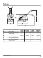
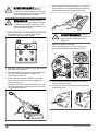
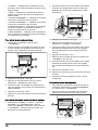
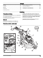
Work area safety
• During operation, keep bystanders away from the
area shown in the illustration below. The operator
must be very careful in this area during operation.
• Make sure that only approved persons are in the
work area.
• Do not use the product in fog, rain, strong winds,
cold weather, risk of lightning or other bad weather
conditions. To use the product in bad weather or
in wet locations can have a negative effect on your
alertness. Bad weather can cause dangerous work
conditions.
• Look out for persons, objects and situations that can
prevent safe operation of the product.
• PG 690 RC, PG 830 RC: The product can be
operated by a remote control for long distances. Do
not operate the product unless you have clear view
of the product and its risk area. Cordon off the work
area to prevent injury to bystanders.
• Keep the work area sufficiently illuminated.
• Do not use the product in areas where fire or
explosions can occur.
Electrical safety
WARNING: There is always a risk of
shocks from electrical products. Do not use
the product in bad weather conditions. Do
not touch lightning conductors and metal
objects. Always use the product as given in
this operator’s manual to prevent injury.
WARNING: Always use a power supply
with RCD (residual-current device). An RCD
decreases the risk of electrical shock.
WARNING: High voltage. There are
unprotected parts in the power unit. Always
disconnect the power plug before you open
the door to the electrical box.
CAUTION: The power supply from
the product or generator must be sufficient
and constant to make sure that the motor
operates without problems. Incorrect voltage
causes the power consumption and the
temperature of the motor to increase until
the safety circuit releases. The dimension
of the power cord must agree with national
and local regulations. The dimension of the
mains socket must agree with the amperage
for the electrical socket and extension cable
of the product.
If the power mains has higher system
resistance, short voltage drop can occur
when the product is started. This can
influence the operation of other products, for
example flicker on the lights.
• Make sure that the power, fuse and mains voltage
are the same as the voltage shown on the rating
plate of the product.
• Always stop the product before you disconnect the
power plug.
• Do not use the product if the power cord or power
plug is damaged. Hand it in to an approved service
center for repair. A damaged power cord can cause
serious injury and death.
• Use the power cord correctly. Do not use the power
cord to move, pull or disconnect the product. Pull the
power plug to disconnect the power cord. Do not pull
the power cord.
• Do not operate the product in water depths where
the equipment of the product gets wet. The
equipment can become damaged and the product
can become live and cause injury.
• Do not get more moisture into the product than
the water supplied by the water system. Keep the
product away from rain. Water that goes into the
product increases the risk of electrical shock.
• Always disconnect the power cord before you
connect or disconnect the connection for the motor
cable and the electrical enclosure.
1163 - 005 - 09.12.2022 11

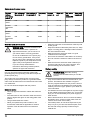
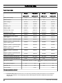
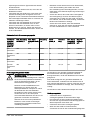
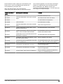
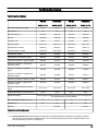
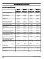
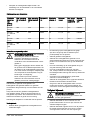
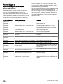
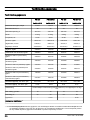
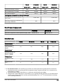
Guide values for power source
Nominal
voltage
from power
source, V
Min. voltage at
the product, V
Max. voltage at
the product, V
Frequency,
Hz
Nominal
current, A
Motor out-
put
Min. cable
area
mm2/AWG
Max. cable
length m/ft
PG 690
3x220
200 240 50/60 50 11+1.5 10/7 190/620
PG 690
3x400/440/
480
380 480 50/60 30 11+1.5 6/9 190/620
PG 830
3x220
200 240 50/60 50 11+1.5 10/7 190/620
PG 830
3x400/440/
480
380 480 50/60 30 15+1.5 6/9 190/620
Grounded product instructions
WARNING: Incorrect connection can
result in electrical shock. Speak to an
approved electrician if you are not sure if
your mains outlet is correctly grounded.
Do not do modifications to the power plug
from its factory specification. If the power
plug or power cord is damaged or must be
replaced, speak to your Husqvarna service
agent. Obey local regulations and laws.
If you do not fully understand the
instructions about the grounded product,
speak to an approved electrician.
Use only grounded outdoor extension cables with
grounding plugs and grounding outlet that accepts the
product power plug.
The product has a grounded power cord and power
plug. Always connect the product to a grounded mains
outlet. This decreases the risk of electrical shock if there
is a malfunction.
Do not use electrical adapters with the product.
Extension cables
• Use only approved extension cables with sufficient
length.
• The rated value on the extension cable must be the
same or higher than given on the rating plate of the
product.
• Use grounded extension cables.
• When you operate the product outdoors, use
an extension cable that is applicable for outdoor
operation. This decreases the risk of electrical
shock.
• Keep the connection to the extension cable dry and
off the ground.
• Keep the extension cable away from heat, oil, sharp
edges or moving parts. A damaged cable increases
the risk of electrical shock.
• Make sure that the extension cable is in good
condition and not damaged.
• Do not use the extension cable while it is wound up.
This can cause the extension cable to become too
hot.
• Make sure that the extension cable is behind you
and the product when you use the product. This
prevents damage to the extension cable.
Battery safety
WARNING: Read the warning
instructions that follow before you use the
product.
• Only use the batteries that we recommend for your
product. The batteries are software encrypted.
• Use only original batteries for this product. There is
a risk of explosion if the batteries are replaced with
a battery of incorrect type. Speak to your dealer for
more information.
• Use batteries that are rechargable as a power supply
for the related Husqvarna products only. To prevent
injury, do not use the battery as a power supply for
other devices.
• Risk of electrical shock. Do not connect the battery
terminals to keys, screws or other metal. This can
cause a short circuit of the battery.
• If the battery leaks, do not let the liquid touch your
body or eyes. If you have touched the liquid, clean
the area with a large quantity of water and get
medical aid.
12 1163 - 005 - 09.12.2022

• Do not use batteries that are non-rechargable.
• Do not do modifications to the battery.
• Do not put objects into the air slots of the battery.
• Keep the battery away from sunlight, heat or open
flame. The battery can cause an explosion and
cause burns and/or chemical burns.
• Keep the battery away from rain and wet conditions.
• Keep the battery away from microwaves and high
pressure.
• Do not try to disassemble or break the battery.
• Use the battery in temperatures between -10 °C/14
°F and 40 °C/104 °F.
• Do not clean the battery or the battery charger with
water. Refer to
To clean the battery and the battery
charger on page 34
.
• Do not use a defective or damaged battery.
• Keep batteries in storage away from metal objects
such as nails, screws or jewelry.
• Keep the battery away from children.
Safety devices on the product
WARNING: Read the warning
instructions that follow before you use the
product.
• Do not use a product with defective safety devices.
• Do a check of the safety devices regularly. If
the safety devices are defective, speak to your
Husqvarna service agent.
• Do not make modifications to safety devices.
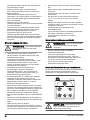
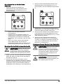
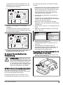
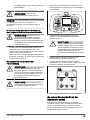
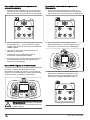
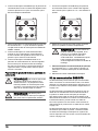
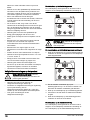
Emergency stop button on the control panel
The emergency stop button is used to quickly stop the
motor. The emergency stop button breaks the mains
power supply.
CAUTION: Do not use the emergency
stop button on the control panel as the stop
button for the product.
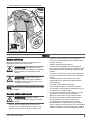
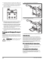
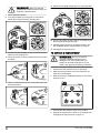
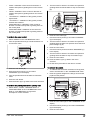
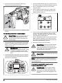
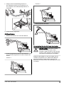
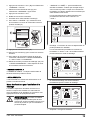
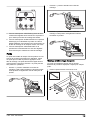
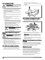
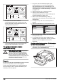
To do a check of the emergency stop button on the
control panel
1. Turn the emergency stop button (A) on the control
panel clockwise to make sure that the emergency
stop button is disengaged.
B
A
2. Turn the ON/OFF switch (B) on the control panel to 1
to start the motor. The LED adjacent to the ON/OFF
switch comes on.
3. Push the emergency stop button on the control
panel.
4. Make sure that LED adjacent to the ON/OFF switch
goes off.
5. Turn the emergency stop button on the control panel
clockwise to disengage.
Emergency stop button on the remote control
The emergency stop button is used to quickly stop the
motor. The emergency stop button breaks the mains
power supply. The emergency stop button on the remote
control cannot be used when the product is operated
manually.
CAUTION: Do not use the emergency
stop button on the remote control as the
stop button for the product.
1163 - 005 - 09.12.2022 13

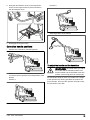
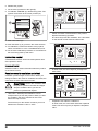
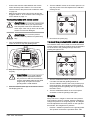
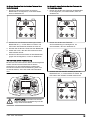
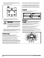
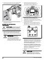
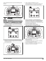
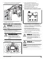
To do a check of the of the emergency stop button on
the remote control
1. Turn the emergency stop button on the control panel
clockwise to make sure that the emergency stop
button is disengaged.
2. Turn the emergency stop button on the remote
control clockwise to make sure that the emergency
stop button is disengaged.
3. Turn the ON/OFF switch (A) on the control panel to 1
to start the motor. The LED adjacent to the ON/OFF
switch comes on.
A
B
4. Turn the remote control/manual operation switch (B)
on the control panel clockwise for remote control
operation. The LED adjacent to the remote control/
manual operation switch flashes.
5. Push the ON/OFF button (C) on the remote control.
The remote control is on when the display comes on.
D
C
6. Push the emergency stop button (D) on the remote
control.
7. Make sure that LED adjacent to the ON/OFF switch
on the control panel goes off.
8. Turn the emergency stop button on the remote
control clockwise to disengage.
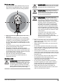
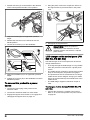
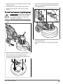
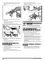
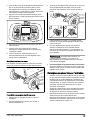
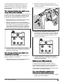
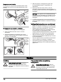
Locking pins for the wheels
The locking pins lock the wheels to the motor when the
product is operated with the remote control.
To do a check of the locking pins for the wheels
1. Make sure that the locking pins are not engaged.
2. Push the product slightly forward and feel the
resistance.
14 1163 - 005 - 09.12.2022

3. Turn the locking pins (A) until the pin of the locking
pin aligns with the notch. Do this on the left and the
right wheel.
A B
4. Start the product. The locking pins go into the lock
position (B) and lock the wheel motors.
5. Push the product slightly forward and feel the
resistance. If the locking pins are correctly engaged,
there is more resistance than when the locking pins
are not engaged.
Note: For remote control operation, an error
message shows in the remote control display if the
locking pins are not engaged correctly.
6. To disengage the locking pins, pull the locking pins
straight out and turn clockwise or counterclockwise.
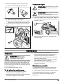
Safety instructions for maintenance
• Keep all parts in good condition and make sure that
all fixtures are correctly tightened.
• Do not use a product that is defective. Do the safety
checks, maintenance and the servicing as given in
this manual. All other maintenance work must be
done by an approved service agent.
• Stop the product when you replace the diamond
tools. Turn the ON/OFF switch to 0 and push the
emergency stop button.
• Do the inspection and/or maintenance with the motor
stopped and the power plug disconnected.
• Do the maintenance to make sure that the product
operates correctly. Refer to
Maintenance schedule
on page 33
.
Operation
Introduction
WARNING: Before you operate the
product, you must read and understand the
safety chapter.
To remove the product from the
package
WARNING: Move the product from the
pallet carefully and safely. The product is
heavy and can cause serious injury if it falls.
• Make sure that all items that is shown in the product
overview, are included. Refer to
Product overview,
right side on page 2
. Speak to your Husqvarna
dealer if an item is missing or damaged before you
move the product from the pallet.
• Remove all package straps and wheel chocks.
• Make sure that the area is clear and that you have
sufficient space to move the product.
• Make sure that there is no risk that you or the
product can fall.
• Use lifting equipment or ramps to move the product
from the pallet. The product is heavy. Move the
product safely. Refer to
To lift the product on page
44
.
To do before you operate the product
1. Read the operator's manual carefully and make sure
that you understand the instructions.
2. Put on necessary personal protective equipment.
Refer to
Personal protective equipment on page 10
.
3. Make sure that only approved persons are in the
work area.
4. Do daily maintenance. Refer to
Maintenance
schedule on page 33
.
5. Make sure that the product is assembled correctly
and is not damaged.
6. Put the product on the work area. Make sure that the
transportation of the product to and in the work area
is done safely and correctly. Refer to
Transportation
on page 42
.
7. Make sure that there are diamond tools on the tool
plates and that the diamond tools and tool plates are
tightly attached.
8. Connect a dust extractor to the product. Refer to
To
connect a dust extractor on page 18
.
9. Adjust the handle and the handlebar to an applicable
operation height. Refer to
To adjust the handle and
the handlebar on page 19
.
10. Make sure that the motor cables are connected
to the electrical enclosure before the product is
connected to a mains outlet. Refer to
To install and
remove the grinding head on page 37
.
1163 - 005 - 09.12.2022 15

11. Connect the product to a power source. Refer to
To
connect the product to a power source on page 20
.
12. Turn the emergency stop button on the control panel
clockwise to make sure that the emergency stop
button is disengaged.
13. Make sure that you know the direction of rotation of
the grinding head and the grinding discs when you
use direction diamond tools such as Piranhas.
14. PG 690 RC, PG 830 RC: If the product is operated
manually, attach the remote control to the product.
The rear side of the remote control holder has a
magnet. Refer to
To attach the remote control to the
remote control holder on page 22
.
15. Put the support wheel in operation position. Refer
to
To set the support wheel in operation position on
page 43
.
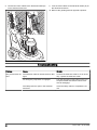
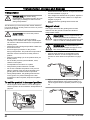
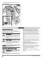
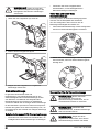
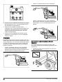
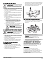
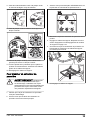
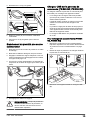
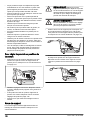
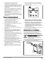
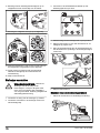
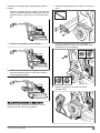
To engage and disengage the support
frame
The product has a support frame that is used to tilt the
product rearward. Also, the support frame is used as a
suspension device to hang the dust extractor hose and
the power cord on.
WARNING: Be careful when you move
the support frame. The moving parts can
cause injury.
1. Lift the support frame (A) a small distance.
A
2. Lower the support frame (B).
B
3. Fold up the support frame in the opposite sequence.
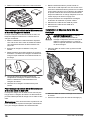
Diamond tools
There are many different types and configurations of
diamond tools for the product. Metal bonded diamond
tools are used for removal of material and resin bonded
diamond tools are used to polish surfaces. Select the
correct diamond tools for the surface. Speak to your
Husqvarna dealer or go to www.husqvarnacp.com for
support to select the correct tool.
Disc holder alternatives for diamond tools
• Use a Redi lock disc holder to attach metal bonded
diamond tools.
• Use a resin disc holder to attach plastic bonded
diamond tools.
Full set and half set of diamond tools
The configuration of the diamond tool segments has
an effect on the end quality of the surface. The
configuration also has an effect on the operation rate
of the product.
16 1163 - 005 - 09.12.2022

• Full set of diamond tools: This configuration is
applicable for a flat floor finish.
• Half set of diamond tools: This configuration is
applicable when a flat floor finish is not necessary.
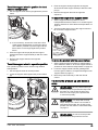
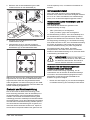
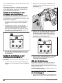
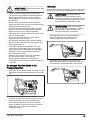
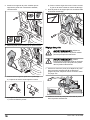
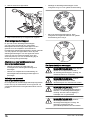
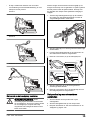
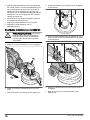
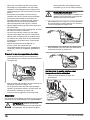
To replace the diamond tools
WARNING: Always disconnect the
power plug before you replace the diamond
tools, to prevent accidental start.
WARNING: Use protective gloves, as
diamond tools can become very hot.
WARNING: Use approved respiratory
protection when you replace the diamond
tools. The dust below the grinding head is
dangerous to your health.
WARNING: Use the dust extractor
when you replace the diamond tools. The
dust extractor will decrease the dust that can
cause health problems.
CAUTION: All the grinding discs must
always have the same number and type of
diamonds. The height of the diamonds must
be the same on all grinding discs.
1. Turn the ON/OFF switch (A) on the control panel to
0. The LED adjacent to the ON/OFF switch goes off.
A
B
2. Push the emergency stop button (B) on the control
panel.
3. Set the handle in servicing position. Refer to
Operation handle positions on page 19
.
4. If weights are installed, adjust the weights to a
rearward position. Refer to
To adjust the weights on
page 33
.
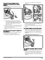
5. Engage the support frame. Refer to
To engage and
disengage the support frame on page 16
.
6. Hold the handlebar and with one foot on the support
frame tilt the product rearward. Tilt the product until
the handlebar is on the floor.
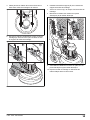
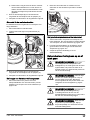
1163 - 005 - 09.12.2022 17

WARNING: Make sure that the
product is in a stable position before you
replace the diamond tools.
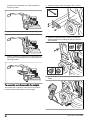
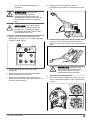
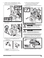
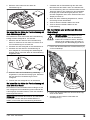
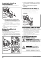
7. Put on protective gloves.
8. Turn the tool plate (C) to the right or to the left to
unlock the tool plate from the grinding disc.
C
D
9. Pull the tool plate straight out (D) to remove the tool
plate from the grinding disc.
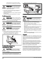
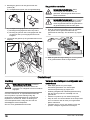
10. Use a hammer to remove the diamond tools from the
tool plate.
11. Attach new diamond tools to the tool plate with a soft
hit of the hammer.
12. Attach the tool plate straight (E) on the grinding disc.
E
F
13. Turn the tool plate (F) to the right or to the left to lock
the tool plate to the grinding disc.
14. Carefully lift the product to operation position. Use
the handlebar and the support frame for support.
15. Disengage the support frame.
To connect a dust extractor
WARNING: Do not use the dust
extractor if the dust extractor hose is
damaged. The risk increases that you
breathe in dust that is dangerous to your
health. Use approved respiratory protection.
1. Examine the dust extractor hose for damages.
2. Make sure that the filters in the dust extractor are
clean and not damaged.
3. Make sure that the STOP/RUN switch on the control
panel is set to 0.
4. Connect the dust extractor hose to the product.
5. Engage the support frame. Refer to
To engage and
disengage the support frame on page 16
.
18 1163 - 005 - 09.12.2022

6. Hang the dust extractor hose on the suspension
device on the support frame to prevent tension in
the dust extractor hose.
7. Disengage the support frame.
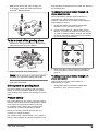
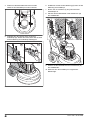
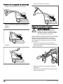
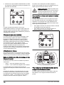
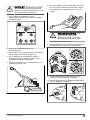
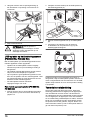
Operation handle positions
• Position of the handle for manual operation:
• There are 2 recommended positions of the handle
for remote control operation and transportation of the
product.
Position 1:
Position 2:
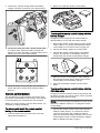
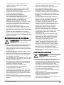
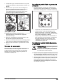
• Servicing position of the handle:
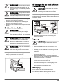
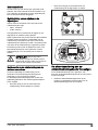
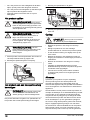
To adjust the handle and the handlebar
WARNING: Be careful when you adjust
the handle and the handlebar. Make sure
that the handle and the handlebar locks into
position. The moving parts can cause injury.
Set the handle height as close as possible to the height
of the operators hip. During operation the product can
pull to the side. The hip of the operator can help to stop
this movement to the side.
1163 - 005 - 09.12.2022 19

1. Pull the lock lever (A) on the handle in the direction
of the control panel and hold it in this position.
A
B
2. Adjust the handle (B) to an applicable operation
height.
3. Release the lock lever on the handle to lock the
handle position.
4. Loosen the 4 screws (C) on the handlebar.
D
CE
5. Adjust the handlebar (D) to an applicable operation
height.
6. Tighten the 4 screws (E) on the handlebar to lock the
handlebar position.
To connect the product to a power
source
1. Connect the power plug of the product to the
extension cable.
2. Connect the extension cable to a mains outlet.
3. Engage the support frame. Refer to
To engage and
disengage the support frame on page 16
.
4. Hang the power cord on the suspension device on
the support frame to prevent tension in the power
cord.
5. Disengage the support frame.
CAUTION: When the product is
connected to a dust extractor, the dust
extractor must be connected to a 3-phase
power source.
USB charger on the control panel (PG
690 RC, PG 830 RC)
The USB charger on the control panel can be used to
charge mobile devices.
• To charge through the USB charger is only possible
when the product is connected to a 3-phase power
source.
• The mobile device continues to charge if the product
stops or the emergency stop button is engaged.
• The product does not set a time limit for how long a
mobile device can be charged. Charge your mobile
device as recommended by the manufacturer of the
mobile device.
• The USB charger supplies a maximum output of
10W.
To charge a mobile device (PG 690 RC, PG
830 RC)
1. Connect the product to a 3-phase power source.
Refer to
To connect the product to a power source
on page 20
.
20 1163 - 005 - 09.12.2022
La page est en cours de chargement...
La page est en cours de chargement...
La page est en cours de chargement...
La page est en cours de chargement...
La page est en cours de chargement...
La page est en cours de chargement...
La page est en cours de chargement...
La page est en cours de chargement...
La page est en cours de chargement...
La page est en cours de chargement...
La page est en cours de chargement...
La page est en cours de chargement...
La page est en cours de chargement...
La page est en cours de chargement...
La page est en cours de chargement...
La page est en cours de chargement...
La page est en cours de chargement...
La page est en cours de chargement...
La page est en cours de chargement...
La page est en cours de chargement...
La page est en cours de chargement...
La page est en cours de chargement...
La page est en cours de chargement...
La page est en cours de chargement...
La page est en cours de chargement...
La page est en cours de chargement...
La page est en cours de chargement...
La page est en cours de chargement...
La page est en cours de chargement...
La page est en cours de chargement...
La page est en cours de chargement...
La page est en cours de chargement...
La page est en cours de chargement...
La page est en cours de chargement...
La page est en cours de chargement...
La page est en cours de chargement...
La page est en cours de chargement...
La page est en cours de chargement...
La page est en cours de chargement...
La page est en cours de chargement...
La page est en cours de chargement...
La page est en cours de chargement...
La page est en cours de chargement...
La page est en cours de chargement...
La page est en cours de chargement...
La page est en cours de chargement...
La page est en cours de chargement...
La page est en cours de chargement...
La page est en cours de chargement...
La page est en cours de chargement...
La page est en cours de chargement...
La page est en cours de chargement...
La page est en cours de chargement...
La page est en cours de chargement...
La page est en cours de chargement...
La page est en cours de chargement...
La page est en cours de chargement...
La page est en cours de chargement...
La page est en cours de chargement...
La page est en cours de chargement...
La page est en cours de chargement...
La page est en cours de chargement...
La page est en cours de chargement...
La page est en cours de chargement...
La page est en cours de chargement...
La page est en cours de chargement...
La page est en cours de chargement...
La page est en cours de chargement...
La page est en cours de chargement...
La page est en cours de chargement...
La page est en cours de chargement...
La page est en cours de chargement...
La page est en cours de chargement...
La page est en cours de chargement...
La page est en cours de chargement...
La page est en cours de chargement...
La page est en cours de chargement...
La page est en cours de chargement...
La page est en cours de chargement...
La page est en cours de chargement...
La page est en cours de chargement...
La page est en cours de chargement...
La page est en cours de chargement...
La page est en cours de chargement...
La page est en cours de chargement...
La page est en cours de chargement...
La page est en cours de chargement...
La page est en cours de chargement...
La page est en cours de chargement...
La page est en cours de chargement...
La page est en cours de chargement...
La page est en cours de chargement...
La page est en cours de chargement...
La page est en cours de chargement...
La page est en cours de chargement...
La page est en cours de chargement...
La page est en cours de chargement...
La page est en cours de chargement...
La page est en cours de chargement...
La page est en cours de chargement...
La page est en cours de chargement...
La page est en cours de chargement...
La page est en cours de chargement...
La page est en cours de chargement...
La page est en cours de chargement...
La page est en cours de chargement...
La page est en cours de chargement...
La page est en cours de chargement...
La page est en cours de chargement...
La page est en cours de chargement...
La page est en cours de chargement...
La page est en cours de chargement...
La page est en cours de chargement...
La page est en cours de chargement...
La page est en cours de chargement...
La page est en cours de chargement...
La page est en cours de chargement...
La page est en cours de chargement...
La page est en cours de chargement...
La page est en cours de chargement...
La page est en cours de chargement...
La page est en cours de chargement...
La page est en cours de chargement...
La page est en cours de chargement...
La page est en cours de chargement...
La page est en cours de chargement...
La page est en cours de chargement...
La page est en cours de chargement...
La page est en cours de chargement...
La page est en cours de chargement...
La page est en cours de chargement...
La page est en cours de chargement...
La page est en cours de chargement...
La page est en cours de chargement...
La page est en cours de chargement...
La page est en cours de chargement...
La page est en cours de chargement...
La page est en cours de chargement...
La page est en cours de chargement...
La page est en cours de chargement...
La page est en cours de chargement...
La page est en cours de chargement...
La page est en cours de chargement...
La page est en cours de chargement...
La page est en cours de chargement...
La page est en cours de chargement...
La page est en cours de chargement...
La page est en cours de chargement...
La page est en cours de chargement...
La page est en cours de chargement...
La page est en cours de chargement...
La page est en cours de chargement...
La page est en cours de chargement...
La page est en cours de chargement...
La page est en cours de chargement...
La page est en cours de chargement...
La page est en cours de chargement...
La page est en cours de chargement...
La page est en cours de chargement...
La page est en cours de chargement...
La page est en cours de chargement...
La page est en cours de chargement...
La page est en cours de chargement...
La page est en cours de chargement...
La page est en cours de chargement...
La page est en cours de chargement...
La page est en cours de chargement...
La page est en cours de chargement...
La page est en cours de chargement...
La page est en cours de chargement...
La page est en cours de chargement...
La page est en cours de chargement...
La page est en cours de chargement...
La page est en cours de chargement...
La page est en cours de chargement...
La page est en cours de chargement...
La page est en cours de chargement...
La page est en cours de chargement...
La page est en cours de chargement...
La page est en cours de chargement...
La page est en cours de chargement...
La page est en cours de chargement...
La page est en cours de chargement...
La page est en cours de chargement...
La page est en cours de chargement...
La page est en cours de chargement...
La page est en cours de chargement...
La page est en cours de chargement...
-
 1
1
-
 2
2
-
 3
3
-
 4
4
-
 5
5
-
 6
6
-
 7
7
-
 8
8
-
 9
9
-
 10
10
-
 11
11
-
 12
12
-
 13
13
-
 14
14
-
 15
15
-
 16
16
-
 17
17
-
 18
18
-
 19
19
-
 20
20
-
 21
21
-
 22
22
-
 23
23
-
 24
24
-
 25
25
-
 26
26
-
 27
27
-
 28
28
-
 29
29
-
 30
30
-
 31
31
-
 32
32
-
 33
33
-
 34
34
-
 35
35
-
 36
36
-
 37
37
-
 38
38
-
 39
39
-
 40
40
-
 41
41
-
 42
42
-
 43
43
-
 44
44
-
 45
45
-
 46
46
-
 47
47
-
 48
48
-
 49
49
-
 50
50
-
 51
51
-
 52
52
-
 53
53
-
 54
54
-
 55
55
-
 56
56
-
 57
57
-
 58
58
-
 59
59
-
 60
60
-
 61
61
-
 62
62
-
 63
63
-
 64
64
-
 65
65
-
 66
66
-
 67
67
-
 68
68
-
 69
69
-
 70
70
-
 71
71
-
 72
72
-
 73
73
-
 74
74
-
 75
75
-
 76
76
-
 77
77
-
 78
78
-
 79
79
-
 80
80
-
 81
81
-
 82
82
-
 83
83
-
 84
84
-
 85
85
-
 86
86
-
 87
87
-
 88
88
-
 89
89
-
 90
90
-
 91
91
-
 92
92
-
 93
93
-
 94
94
-
 95
95
-
 96
96
-
 97
97
-
 98
98
-
 99
99
-
 100
100
-
 101
101
-
 102
102
-
 103
103
-
 104
104
-
 105
105
-
 106
106
-
 107
107
-
 108
108
-
 109
109
-
 110
110
-
 111
111
-
 112
112
-
 113
113
-
 114
114
-
 115
115
-
 116
116
-
 117
117
-
 118
118
-
 119
119
-
 120
120
-
 121
121
-
 122
122
-
 123
123
-
 124
124
-
 125
125
-
 126
126
-
 127
127
-
 128
128
-
 129
129
-
 130
130
-
 131
131
-
 132
132
-
 133
133
-
 134
134
-
 135
135
-
 136
136
-
 137
137
-
 138
138
-
 139
139
-
 140
140
-
 141
141
-
 142
142
-
 143
143
-
 144
144
-
 145
145
-
 146
146
-
 147
147
-
 148
148
-
 149
149
-
 150
150
-
 151
151
-
 152
152
-
 153
153
-
 154
154
-
 155
155
-
 156
156
-
 157
157
-
 158
158
-
 159
159
-
 160
160
-
 161
161
-
 162
162
-
 163
163
-
 164
164
-
 165
165
-
 166
166
-
 167
167
-
 168
168
-
 169
169
-
 170
170
-
 171
171
-
 172
172
-
 173
173
-
 174
174
-
 175
175
-
 176
176
-
 177
177
-
 178
178
-
 179
179
-
 180
180
-
 181
181
-
 182
182
-
 183
183
-
 184
184
-
 185
185
-
 186
186
-
 187
187
-
 188
188
-
 189
189
-
 190
190
-
 191
191
-
 192
192
-
 193
193
-
 194
194
-
 195
195
-
 196
196
-
 197
197
-
 198
198
-
 199
199
-
 200
200
-
 201
201
-
 202
202
-
 203
203
-
 204
204
-
 205
205
-
 206
206
-
 207
207
-
 208
208


dans d''autres langues
- English: Husqvarna PG 690 User manual
- Deutsch: Husqvarna PG 690 Benutzerhandbuch
- Nederlands: Husqvarna PG 690 Handleiding
Documents connexes
-
Husqvarna DE 110 SH Manuel utilisateur
-
Husqvarna BMG 444 Manuel utilisateur
-
Husqvarna DE 110i Manuel utilisateur
-
Husqvarna BMS 220 ADB Manuel utilisateur
-
-
-
Husqvarna S 13 Single Phase HEPA Dust Extractor Le manuel du propriétaire
-
-
Husqvarna FS400LV Manuel utilisateur
-
