
Produkt-
information
Siedle-Vario
Montageanleitung
Siedle-Vario
Mounting instructions
Siedle-Vario
Instruction de montage
Siedle-Vario
Istruzioni per il montaggio
Siedle-Vario
Montagehandleiding
Siedle-Vario
Montagevejledning
Siedle-Vario
Monteringsanvisning
Siedle-Vario
Návod k montáži

4
Mounting instructions
1 The ideal mounting height for
door loudspeaker units lies between
1.40 and 1.60 m above the height
of the finished floor.
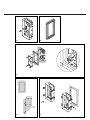
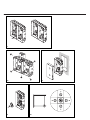
Surface mounting, vertical or
horizontal
2 f the plaster is highly uneven,
additionally glue the four provided
distance washers on the back panel
of the surface mount housing
GA 611-... over the screw holes on
the already mounted washers (a).
Open the cable entry (b) at the
required position and glue the
provided water deflector (c) like a
roof on the back panel.
Cable entries which are not required
must remain closed.
3 Strip the connecting cable of its
sheathing to max. 3 cm, insert
through the back panel into the
GA 611-... and fasten the housing
on the wall. Pay attention to the
indication „top“.
4 In order to prevent material
fatigue of the catch lugs, ensure
that they are not pushed backwards
but correctly locked in position. If
necessary, release these using a
small screwdriver.
5 Remove the combination terminal
strip from the module packaging,
centre on the retaining plate turned
by around 45° to the left, and lock
into position with a quarter turn in
the clockwise direction so that the
terminal designations are legible
vertically one above the other.
6 Press the connecting cables with
the cable holding-down devices onto
the floor of the housing. In the case
of multiple-row units, fix the
connecting wires using the wire
holding brackets. Connect the unit
using the relevant circuit diagram at
the combination terminal strip.
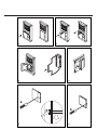
7 Insert the mounting frame in such
a way that the sealing film is located
at the upper and right-hand edge of
the mounting frame. When
positioned horizontally, multiple-row
housings must always be fitted from
bottom to top, so ensuring that the
sealing film of the lower mounting
frame overlaps that of the lower
frame in fish-scale formation. When
mounting vertically, ensure that the
lateral film is positioned under the
adjacent mounting frame. Clip the
mounting frames in the surface
mount housing using a light
pressure.
Catch lugs which are not required
can be pressed out of the surface
mount housing with a screwdriver
and moved if required.
8 The mounting frame can be
removed from the GA 611-... by
pressing back the red catches.
Note! Turning back can cause the
catches to become locked in
position. (see Fig. 4)
Flush mounting
9 Position flush mounting housings
GU 611-... next to each other and
connect using the provided system
connectors. These connectors are
mounted on a pin in the GU 611-...
together with the cable holding-
down device as injection moulded
parts. The connectors can be broken
off by a twisting action.
10 For combination frames bigger
than 300 x 300 mm, the corners of
the GU 611-... must be broken out.
For in-row mounting involving a
large number of units, specially
produced combination frames are
required.
11 (Not illustrated)
Break out the cable gland between
the housing units.
12 Plaster in the horizontal or
vertical GU 611-... and insert the
provided cardboard into the
GU 611-... . This serves as a plaster
protection and for reinforcement
and remains in the housing until
final assembly. Up to a maximum of
15 mm plaster height difference can
be compensated.
13 Remove the combination
terminal strip from the module
packaging, centre on the retaining
plate turned appr. 45° to the left
and lock into position with a quarter
turn in the clockwise direction so
that the terminal designations are
legible vertically one above the
other.
14 If combination frames of 600 X
500 mm and bigger are used, a
cross is created in the substructure
of the peripheral frame. There is an
adjusting screw let into this cross,
which allows the substructure to be
supported away from the flush
mount housing. Turn the adjusting
screw inwards until the substructure
is positioned parallel to the front.
This guarantees that the front of the
inserted module is correctly aligned.
15 Strip the connecting cables of
their sheathing, press onto the floor
of the housing, fix using the cable
holding-down devices and connect
the unit in accordance with the
relevant circuit diagram at the
combination terminal strip.
16 Insert the mounting frame
together with the combination
frame in such a way that the sealing
profile of the combination frame is
open towards the bottom. The
mounting frame must be inserted in
such a way that the sealing film is
located at the upper and right-hand
edge of the mounting frame. When
positioned horizontally, multiple-row
housings must always be fitted from
bottom to top, so ensuring that the
sealing film of the lower mounting
frame overlaps that of the lower
frame in fish-scale formation. When
mounting vertically, ensure that the
lateral film is positioned under the
adjacent mounting frame. Clip the
mounting frames in the surface
mount housing using a light
pressure.
17 Press the combination frame
together with the mounting frame
completely against the wall and
screw in the flush mount housing
using the provided quick-locking
screws, turning a quarter turn to the
right (until the stop).
Hollow wall mounting
18 Trace the cut-out for the flush-
mount housing GU 611-... . To do
this, lay the provided cardboard
template flat on the wall and draw
on the slit and drill hole markings.
English
Mounting

5
Draw the rectangle, drill the holes
for the screws of the hollow wall
mounting fixture, and make the cut-
out.
19 Mount hollow wall mounting
accessory ZHB 612-... at the
GU 611-... and turn the clamping
plate behind the flush mount
housing.
20 (Not illustrated)
Insert the GU 611-... with mounted
ZHB 612-... into the cutout and
screw.
Inserting the modules
21 (Not illustrated)
Insert the plug of the flat ribbon
cable into the combination terminal
strip.
22 Applying a light pressure,
underpin the module in the module
slot of the MR 611-... opposite the
movable locking bolt. Exerting a
slightly higher degree of pressure,
clip into place on the other side.
Removing modules
23 Removing a module from the
mounting frame: The release
mechanism is initiated by insertion
of the Vario key with a slight
pressure. The opening for the Vario
key is always located between the
modules or between the module
and the panel. The Vario key is
provided with the mounting frame.
Releasing vacates one or two
modules simultaneously. Access to
the release mechanism can be
additionally secured using the theft
guard accessory ZDS 601-... with
theft guard controller DSC 602-...
(see product information
ZDS 601-...).
Servicing / troubleshooting
24 Release the wire bracket on the
back of the module and clip from
the front into the retainer at the
combination terminal strip.
This allows the modules to be
performance tested and measured
through. After the completion of
servicing, reposition the retaining
bracket on the back of the module.
Module illumination
In order to permit brightness-
dependent switching of the module
lighting, the energy-saving circuit
ZE 601-0 can be used at an
IM 611-... .
25 Exchanging the tubular lamp
(18 V/3 W order no. 015762): To do
this the wire bracket on the back of
the module must be swivelled away,
the cover opened and the tubular
lamp exchanged if necessary.
Reposition the retaining bracket on
the back of the module after closing
the cover.
Inscription of the button mo-
dule/info module
26 Open the call button module
TM 611-... using a screwdriver and
remove the inscription pocket. To
insert, underpin the inscription
pocket on one side and close using a
slight pressure.
27 At information module
IM 611-... , release the clip bar at
the side edge and remove the
inscription pocket. To insert,
underpin the inscription pocket on
one side and close using a slight
pressure.
Further supplies of the inscription
inserts made of special water-
repellent paper can be ordered on
request. Make use of the Siedle
lettering service! Please apply for
more information from the
responsible Siedle agent.
Care instructions
In order to retain the flawless
appearance of Siedle door loud-
speaker stations, clean regularly
using a mild soap. Then rub dry
using a soft cloth.
Instructions de montage
1 La hauteur de montage idéale des
installations de portiers électriques
se situe entre 1,40 et 1,60 m du sol.
Montage vertical ou horizontal
en saillie
2 En cas de grande inégalité du mur,
collez les quatre rondelles
d´écartement jointes sur les rondelles
(a) déjà montées sur la face arrière
du boîtier en saillie GA 611-... Ouvrir
l´orifice passe-fils (b) à l´endroit
désiré et collez la pièce hydrofuge (c)
comme un toit sur la façade arríère.
Les orifices passe-fils non utilisés
doivent rester fermés.
3 Dénudez le câble de branchement
près du mur sur une longueur de 3
cm max., introduisez-le dans le
boîtier GA 611-... à travers l´orifice
et fixez le boîtier au mur. Veillez à la
marque „oben“ (haut).
4 Afin d´éviter une fatigue
mécanique des crans d´arrêt, veillez
à ce qu´ils ne soient pas poussés et
enclenchés vers l´arrière.
Si nécessaire, libérez-les avec un
petit tournevis.
5 Retirez le bornier universel de
l´emballage des modules, le centrer
sur la plaquette de réception en le
tournant de 45° env. vers la gauche,
puis l´enclencher par un quart de
tour dans le sens des aiguilles d´une
montre de sorte que le marquage
des bornes coïncide verticalement.
6 Pressez les fils de branchement et
le serre-fil sur le fond du boîtier; en
cas de plusieurs installations en
ligne, fixez les fils à l´aide des étriers
de retenue et branchez l´installation
sur le bornier universel suivant le
schéma de branchement correspon-
dant.
7 Montez le cadre de montage de
sorte que la feuille d´étanchéïté se
trouve sur les côtés supérieur et droit
du cadre de montage. Pour les
boîtiers alignés horizontalement, il
faut toujours monter les cadres de
montage du bas vers le haut de
sorte que la feuille d´étanchéïté du
cadre de montage inférieur se trouve
sous celle du haut, comme l´imbri-
Français
Montage

15
16
17
18
19

9
10
12
13
14

22
23
24
26
27
25
-
 1
1
-
 2
2
-
 3
3
-
 4
4
-
 5
5
-
 6
6


dans d''autres langues
- English: Siedle Vario
Documents connexes
Autres documents
-
SSS Siedle HTA 811-0 Information produit
-
-
-
-
-
 Alcad UN-001 Manuel utilisateur
-
 Alcad 4 PLUS N Assembly Instructions Manual
-
-
Gaggenau VR 414 611 Guide d'installation
-
Gaggenau VP 414 611 Guide d'installation

