Petsafe PIG20-11041 Le manuel du propriétaire
- Catégorie
- S'occuper d'un animal
- Taper
- Le manuel du propriétaire

Please read this entire guide before beginning
Veuillez lire ce manuel en entier avant de commencer
Gelieve deze gids volledig door te lezen voordat u begint
Por favor, lea detenidamente este manual antes de empezar
Si prega di leggere attentamente la guida all’uso prima di utilizzare il collare
Bitte lesen Sie die ganze Gebrauchsanleitung vor der Inbetriebnahme aufmerksam durch
Operating and Training Guide
Manuel d’utilisation et de dressage
Gebruiksaanwijzing en trainingshandleiding
Manual de funcionamiento y de adiestramiento
Manuale di funzionamento e di addestramento
Gebrauchsanweisung und Trainingsanleitung
PIG20-11041
Little Dog Deluxe
In-Ground Fence
™
Clôture anti-fugue de luxe
In-Ground Fence
™
avec l
pour petits chiens
Deluxe omheiningssysteem met
draad voor kleine honden,
In-Ground Fence
™
Limitador de zona deluxe
In-Ground Fence
™
con cable
para perros pequeños
Sistema antifuga deluxe
In-Ground Fence
™
con lo
per cani di taglia piccola
Luxus-unterirdisches
Rückhaltesystem mit Draht für
kleine Hunde In-Ground Fence
™

2 www.petsafe.net
ENFRES
NL
IT
DE
IMPORTANT SAFETY INFORMATION
Explanation of Attention Words and Symbols used in this guide
This is the safety alert symbol. It is used to alert you to potential personal injury hazards. Obey all
safety messages that follow this symbol to avoid possible injury or death.
WARNING indicates a hazardous situation which, if not avoided, could result in death or
serious injury.
CAUTION, used with the safety alert symbol, indicates a hazardous situation which, if not avoided,
could result in minor or moderate injury.
CAUTION, used without the safety alert symbol, indicates a hazardous situation which, if not avoided, could
result in harm to your pet.
NOTICE is used to address practices not related to personal injury.
• Not for use with aggressive dogs. Do not use this product if your dog is aggressive or if your
dog is prone to aggressive behaviour. Aggressive dogs can cause severe injury. If you are not
sure that this product is right for your dog, please talk to your veterinarian or a certified trainer.
• Underground cables can carry high voltage. Have all underground cables marked before you
dig to bury your wire. In most areas, this is a free service.
• Do not install, connect, or remove your system during a lightning storm. If the storm is close
enough for you to hear thunder, it is close enough to create hazardous surges.
• Follow all safety instructions for your power tools. Be sure to always wear your safety goggles.
• Risk of Electric Shock. Use the Fence Transmitter indoors in a dry location only.
• DO NOT attempt to cut into or pry open the battery. Be sure to discard the used battery properly.
• Risk of injury. Wire on top of the ground may be a trip hazard. Use care in how you place
your wires.
• This system is NOT a solid barrier. The system is designed to act as a deterrent to remind pets
by Static Stimulation to remain in the boundary established. It is important that you reinforce
training with your pet on a regular basis. Since the tolerance level to Static Stimulation varies
from pet to pet, Radio Systems Corporation CANNOT guarantee that the system will, in all
cases, keep a pet within the established boundary. Not all pets can be trained to avoid crossing
the boundary! Therefore, if you have reason to believe that your pet may pose a danger to
others or harm himself if he is not kept from crossing the boundaries, you should NOT rely solely
upon the system to confine your pet. Radio Systems Corporation shall NOT be liable for any
property damage, economic loss or any consequential damages, sustained as a result of any
animal crossing the boundary.

3www.petsafe.net
EN
FR
ES
NL
IT
DE
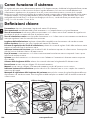
• Please read and follow the instructions in this manual. Proper fit of the collar is important. A collar
worn for too long or made too tight on the pet’s neck may cause skin damage. This is called bed
sores; it is also called decubitus ulcers or pressure necrosis.
• Avoid leaving the collar on the dog for more than 12 hours per day.
• When possible reposition the collar on the pet’s neck every 1 to 2 hours.
• Check the fit to prevent excessive pressure; follow the instructions in this manual.
• Never connect a lead to the electronic collar; it will cause excessive pressure on the contacts.
• When using a separate collar for a lead, don’t put pressure on the electronic collar.
• Wash the dog’s neck area and the contacts of the collar weekly with a damp cloth.
• Examine the contact area daily for signs of a rash or a sore.
• If a rash or sore is found, discontinue use of the collar until the skin has healed.
• If the condition persists beyond 48 hours, see your veterinarian.
For additional information on bed sores and pressure necrosis, please visit our website.
These steps will help keep your pet safe and comfortable. Millions of pets are comfortable while they
wear stainless steel contacts. Some pets are sensitive to contact pressure. You may find after some
time that your pet is very tolerant of the collar. If so, you may relax some of these precautions. It is
important to continue daily checks of the contact area. If redness or sores are found, discontinue use
until the skin has fully healed.
• You may need to trim the hair in the area of the Contact Probes. Never shave the dog’s neck; this
may lead to a rash or infection.
• You should not make the collar any tighter than is required for good contact. A collar that is too
tight will increase the risk of pressure necrosis in the contact area.
• Proper training of your pet is essential to the success of the Petsafe
®
Little Dog Deluxe In-Ground
Fence
™
. During the first 2 weeks of training, do not use the training device on your pet without
direct supervision.
• To prevent an unintended stimulation:
- The receiver collar should not be on your dog when the system is tested.
- Remove the receiver collar before making any changes to your system.
- Before placing the receiver collar on your pet, test the boundary location and width after
any change.
• If possible, do not use an outlet protected with a residual current device (RCD) or ground fault circuit
interrupter (GFCI). The fence system will function properly, but in rare cases, nearby lightning strikes
may cause the RCD or GFCI to trip. Without power, your pet may be vulnerable to escape. You will
have to reset the RCD or GFCI to restore power to the system.
• Avoid damage to the insulation of the loop wire during the install; damage may cause areas of weak
signal and lead to early failure of the loop (wire breaks).
• Use care when mowing or trimming your grass not to cut the loop wire.
• For added protection for the Fence Transmitter when unused for long periods of time or prior to
thunderstorms, disconnect the Loop Boundary Wires and unplug the Power Adapter from the outlet. This
will prevent damage to the Transmitter due to surges.

4 www.petsafe.net
ENFRES
NL
IT
DE
Thank you for choosing PetSafe
®
. You and your pet deserve a companionship that includes memorable
moments and a shared understanding together. Our products and training tools promote a lifestyle of
protection, teaching, and love — essentials that in uence memories for a lifetime. If you have any
questions, please contact the Customer Care Centre. For a listing of Customer Care Centre
telephone numbers, visit our website at www.petsafe.net.
To get the most protection out of your warranty, please register your product within 30 days at www.
petsafe.net. By registering, and keeping your receipt, you will enjoy the product’s full warranty and should
you ever need to call the Customer Care Centre we will be able to help you faster. Most importantly,
PetSafe
®
will never give or sell your valuable information to anyone. Complete warranty information is
available online at www.petsafe.net.
Table of Contents
Components ...........................................................................................................................................5
Other Items You May Need ......................................................................................................................5
How the System Works ............................................................................................................................6
Key De nitions ........................................................................................................................................6
Operating Guide
Locate the Fence Transmitter .................................................................................................................7
Lay Out the System ..............................................................................................................................7
Sample Layouts ...................................................................................................................................8
Position the Boundary Wire ..................................................................................................................9
Connect the Wires to the Fence Transmitter ..........................................................................................11
Prepare the Receiver Collar ................................................................................................................12
Function and Response Table ..............................................................................................................13
Set the Boundary Width and Test the Receiver Collar .............................................................................13
Install the Boundary Wire ...................................................................................................................15
Place the Boundary Flags ...................................................................................................................16
Fit the Receiver Collar ........................................................................................................................16
Training Guide
Be Patient With Your Pet ....................................................................................................................18
Day 1 - Boundary Awareness .............................................................................................................18
Days 2 thru 4 - Continue Boundary Awareness .....................................................................................19
Days 5 thru 8 - Distraction Phase ........................................................................................................20
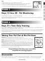
Days 9 thru 14 - Off-lead Supervision ..................................................................................................20
Days 15 thru 30 - Pet Monitoring ........................................................................................................21
Days 31+ Tone Only Training .............................................................................................................21
Taking Your Pet Out of the Pet Area .....................................................................................................21
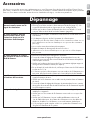
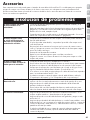
Accessories ..........................................................................................................................................21
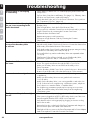
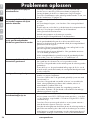
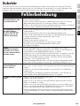
Troubleshooting ....................................................................................................................................22
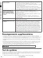
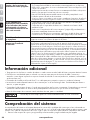
Additional Information ...........................................................................................................................23
System Test ...........................................................................................................................................23
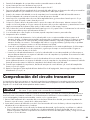
Transmitter Loop Test ..............................................................................................................................24
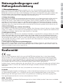
Wire Break Location Test ........................................................................................................................24
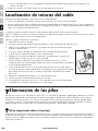
Battery Disposal ....................................................................................................................................25
Terms of Use and Limitation of Liability .....................................................................................................26
Compliance ..........................................................................................................................................26
Français.............................................................................................................................................27
Nederlands .......................................................................................................................................52
Español .............................................................................................................................................77
Italiano ............................................................................................................................................102
Deutsch ...........................................................................................................................................127
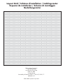
Layout Grid ........................................................................................................................................152

5www.petsafe.net
EN
FR
ES
NL
IT
DE
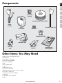
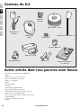
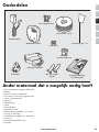
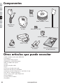
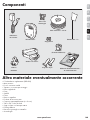
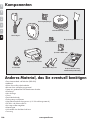
Components
Other Items You May Need
• Additional wire and ags (PRFA-500)
• Tape measure
• Small Phillips screwdriver
• Drill & mounting hardware
• Shovel or lawn edger
• Pliers
• Wire stripping pliers
• Scissors
• Additional wire nuts
• Ground rod and clamp
• Waterproo ng compound (e.g. silicone caulk)
• PVC pipe or water hose
• Circular saw with masonry blade
• Staple gun
• Non-metallic collar and lead
• Lighter
Boundary Flags - 50
Boundary Wire - 150 m (500 ft)
Wire Nuts
Power
Adapter
Fence
Transmitter
Receiver Collar
Operating and
Training Guide
Test Light
Tool
Mounting
Bracket
Battery
(PetSafe
®
RFA-188)
Gel-filled
Capsules

6 www.petsafe.net
ENFRES
NL
IT
DE
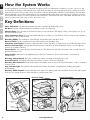
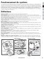
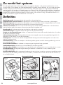
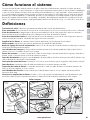
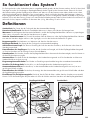
How the System Works
A radio signal travels from the Fence Transmitter through a buried wire, marking the boundaries you wish to set for your dog.
Your dog wears a Receiver Collar that detects the signal at the boundary. As your dog approaches the boundary, the receiver
issues a warning tone. If he proceeds further, he receives a safe but startling Static Stimulation. While harmless, the stimulation
will persuade him to stay in the containment area you’ve established. Boundary ags are a temporary visual aid for your pet;
remove them after training. This Little Dog Deluxe In-Ground Fence™ has been proven safe, comfortable, and effective for pets
over 2.3 kg (5 pounds), neck sizes 15 cm to 40 cm (6" to 16").
Key Definitions
Fence Transmitter: The device that transmits the radio signal through the Boundary Wire.
Pet Area: The area within the Warning Zone where your pet can roam freely.
Warning Zone: The outer edge of the Pet Area where your pet’s Receiver Collar begins to beep, warning him not to go into
the Static Stimulation Zone.
Static Stimulation Zone: The zone beyond the Warning Zone where your pet’s Receiver Collar will emit a Static Stimulation,
signaling him to return to the Pet Area.
Boundary Width: The combination of the Warning Zone and the Static Stimulation Zone.
Receiver Collar: The device that receives the radio signal from the Boundary Wire.
Stimulation Level Button:
The button to adjust the level of Static Stimulation your pet receives in the Static Stimulation Zone.
Receiver Indicator Light: The light that indicates the level of stimulation at which the Receiver Collar is set. This light also
serves as a low battery indicator.
Contact Points: The contacts through which the Receiver Collar delivers the safe Static Stimulation when your pet moves into
the Static Stimulation Zone.
Power Socket: Where the Power Adapter plugs into the Fence Transmitter. The Fence Transmitter is powered by a
standard outlet.
Boundary Control Switch:
The switch to adjust according to the length of Boundary Wire used.
Ground Terminal: The terminal where the Ground Wire connects to the Fence Transmitter.
Boundary Wire Terminals:
The terminals where the Boundary Wires connect to the Fence Transmitter in order to complete a
continuous loop.
Loop Indicator Light: The light that indicates that the Boundary Wire makes a complete loop, enabling the signal to
be transmitted.
Boundary Width Control:
The knob that adjusts the width of the Warning and Static Stimulation Zones. Note: Adjusting the
knob does not change the level of Static Stimulation on the Receiver Collar.
Pet Area
Static Stimulation
Zone
Static Stimulation
Zone
Fence
Transmitter
Warning
Zone
Warning
Zone
Boundary
Width
Contact Points
Battery
Module
Stimulation
Level Button
Receiver
Indicator
Light
(Top)
(Bottom)
Receiver Collar
Boundary Control Switch
Ground
Terminal
Boundary Wire
Terminals
Loop Indicator Light
Power Light
Power
Socket
Boundary Width
Control
Fence Transmitter

7www.petsafe.net
EN
FR
ES
NL
IT
DE
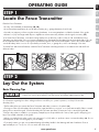
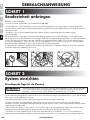
OPERATING GUIDE
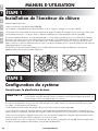
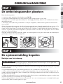
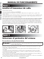
STEP 1
Locate the Fence Transmitter
Place the Fence Transmitter:
• In a dry, well ventilated, protected area (1A, 1B).
• In an area where temperatures do not fall below freezing (e.g., garage, basement, shed, closet).
• Secured to a stationary surface using the mounting hardware. A mounting template is included in the back of this guide.
• At least 1 m (3 ft) from large metal objects or appliances as these items may interfere with the signal consistency (1C).
To mount the Fence Transmitter, screw the mounting bracket onto a stationary surface such as a wall, and slide the Fence
Transmitter onto the bracket. Once you have mounted the Fence Transmitter, the Boundary Wire must exit the building. This can
be accomplished via a window or through a hole drilled through the wall. Ensure the drill path is clear of any utilities. Make
sure the Boundary Wire is not cut off or pinched by a window, door, or garage door, as this can damage it over time.
To prevent res and electrical hazards, install the Fence Transmitter in buildings that are in accordance with state and local
electrical codes.
1A
1B
1 m
(3 ft)
1C
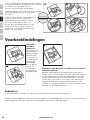
STEP 2
Lay Out the System
Basic Planning Tips
Underground cables can carry high voltage. Have all underground cables marked before you dig
to bury your wire. In most areas this is a free service. Avoid these cables when you dig.
For information regarding how these underground wires can affect your system’s operation, see Step 3 Position the
Boundary Wire.
• The Boundary Wire MUST start at the Fence Transmitter and make a continuous loop back (2A).
• Twisting two sides of the Boundary Wire cancels the signal and allows your pet to cross over that area safely. Plastic or metal
piping will not cancel the signal. Twist the Boundary Wire 30 times per metre (10 times per foot) to cancel the signal (2A).
• Design a layout that is suitable for your property. Sample layouts are provided in this section, and a grid for designing your
layout is provided in the back of this guide.
• Always use gradual turns at the corners with a minimum 1 m (3 ft) radius, to produce a more consistent boundary (2B). Do not
use sharp turns, as this will cause gaps in your boundary.
• To properly contain your pet, we recommend setting a Boundary Width for the Warning and Static Stimulation Zones to
approximately 4 m to 7 m (2 m to 3.5 m on each side of the wire).

8 www.petsafe.net
ENFRES
NL
IT
DE
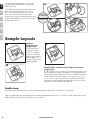
• Avoid making passageways too narrow for
your pet to move about freely (e.g., along the
sides of a house).
• The Receiver Collar can be activated inside
the house if the Boundary Wire runs along
the outside wall of the house. If this occurs,
remove your pet’s Receiver Collar before
bringing him inside, decrease the range using
the Boundary Width Control knob or consider
an alternative layout.
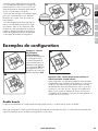
Sample Layouts
Sample 1:
Perimeter Loop
(Single Loop)
The Perimeter Loop
is the most common
layout. This will allow
your pet to freely and
safely roam your entire
property (2C). It can
also protect pools and
landscaping (2D).
D
E
A
C
B
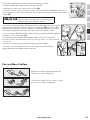
Sample 2 (2E): Perimeter Loop Using Existing Fence
(Single Loop)
This layout allows you to include your existing fence as part of your
layout and keep your pet from jumping out or digging under your
existing fence. It reduces the amount of wire which will need to be
buried. From the Fence Transmitter, run the wire to
A, A to B, B to
C, C to D, D to E, E to A, twist the wires from A back to the Fence
Transmitter. See the “Install the Boundary Wire” section for more
information on attaching the wire to a fence.
Double Loop
A Double Loop must be used when you are not establishing the Boundary Zone on all sides of your property.
When using a Double Loop, the Boundary Wire must be separated by a minimum of 1.5 m (5 ft) to avoid canceling the signal.
Remember that a Double Loop will require twice as much wire.
10 Twists/ft
30 Twists/m
2A
2B

9www.petsafe.net
EN
FR
ES
NL
IT
DE
E
F
B
A
D
C
E
F
C
A
D
B
1.5 m
(5 ft)
1.5 m
(5 ft)
B
A
1.5 m
(5 ft)
E
B
D
C
A
1.5 m
(5 ft)
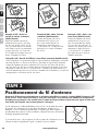
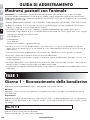
Sample 3 (2F): Front or Back
Property Only (Double Loop)
From the Fence Transmitter, run the
wire to
A, A to B, B to C, C to D, D to E,
E to F, make a U-turn and follow your
path all the way back to A, keeping the
wire separated at least 1.5 m (5 ft).
Twist the wire from A back to the
Fence Transmitter.
Sample 4 (2G): Front
Boundary Only (Double Loop)
From the Fence Transmitter, run the
wire to A, A to B, B back to A keeping
the wire separated at least 1.5 m
(5 ft). Twist the wire from A back to
the Fence Transmitter.
Sample 5 (2H): Lake Access
(Double Loop)
From the Fence Transmitter, run the
wire to A, A to B, make a U-turn
and go to C, C to D, D to E, make
a U-turn and follow your path all
the way back to A keeping wire
separated at least 1.5 m (5 ft).
Twist the wire from A back to the
Fence Transmitter.
Sample 6 (2
I): Wire Loop Attached to Existing Fence (Double Loop)
This layout allows you to include your existing fence as part of your layout and
keep your pet from jumping out or digging under your existing fence. It reduces
the amount of wire which will need to be buried. Run the wire from the Fence
Transmitter to A, A to B, B to C, C to D, D to E, E to F, make a U-turn and follow your
path all the way back to A, keeping the wire separated at least 1.5 m (5 ft). Twist
the wire from A back to the Fence Transmitter. See the “Install the Boundary Wire”
section for more information on attaching the wire to a fence.
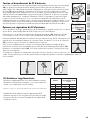
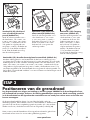
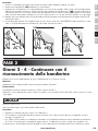
STEP 3
Position the Boundary Wire
Lay out the Boundary Wire using your planned boundary and test the system BEFORE burying the wire or
attaching it to an existing fence. This will make any layout changes easier. Work carefully. A nick in the
wire insulation can diminish the signal strength and create a weak area where your pet can escape.
Running the Boundary Wire parallel to and within 3 m (10 ft) of electrical wires,
neighbouring containment systems, telephone wires, television or antenna cables, or
satellite dishes may cause an inconsistent signal. If you must cross any of these, do
so at 90-degree angles (perpendicularly) (3A).
If separating the wire by at least 3 m (10 ft) from a neighbouring containment
system’s wire does not reduce the inconsistent signal, contact the Customer
Care Centre.
Boundary Wire
3 m
(10 ft)
3 m
(10 ft)
Buried Cabl
e
90˚
E
F
B
A
D
C
1.5 m
(5 ft)
2I

10 www.petsafe.net
ENFRES
NL
IT
DE
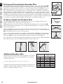
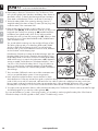
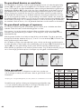
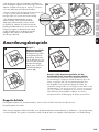
Twisting and Connecting the Boundary Wire
Twisting the Boundary Wire cancels the signal and allows your pet to cross over that area safely (3B).
The signal cannot be cancelled by running the wire through plastic or metal piping. Using shielded
cable in place of the Boundary Wire will also not cancel the signal. Refer to gure (3C) for the correct
method of twisting the wire. You can twist your own wire by cutting two equal lengths of Boundary
Wire supplied and twisting them together. Anchor one end of the wires to something secure and insert
the other end in a power drill. Pull the wire taut. The drill enables you to twist the wire quickly. Twist the
Boundary Wire 30 to 36 times per metre (10 to 12 times per foot) to cancel the signal. Once you have
completed your boundary layout connect one end of the twisted wire to the Perimeter Loop and see Step
4 to connect the other end of the twisted wire to the transmitter. If your layout includes a Secondary Loop to protect landscaping
or pool areas, connect the twisted wire between the Perimeter Loop and the Secondary Loop.
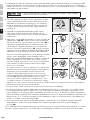
To Splice or Repair the Boundary Wire
If you need additional Boundary Wire to expand your wire loop, you will need to splice the wires
together. Note the locations of all splices for future reference.
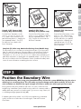
Strip approximately 1 cm (3/8") of insulation off the ends of the Boundary Wires to be spliced (3D).
Make sure the copper Boundary Wire is not corroded. If the Boundary Wire is corroded, cut it back to
expose clean copper wire.
Insert the stripped ends into the wire nut and twist the wire nut around the wires. Ensure that there is no
copper exposed beyond the end of the wire nut. Tie a knot 7.5 cm to 10 cm (3" to 4") from the wire nut
(3E). Ensure that the wire nut is secure on the wire splice.
Once you have securely spliced the wires together, open the lid of the gel- lled splice capsule and insert
the wire nut as deeply as possible into the waterproof gel inside the capsule (3F). Snap the lid of the
capsule shut (3G). For proper system performance, the splice connection must be waterproof.
If your splice pulls loose, the entire system will fail. Make sure your splice is secure. Additional gel- lled
splice capsules and wire nuts are available through the Customer Care Centre.
3E
3F
3G
Additional Boundary Wire
Extra direct burial Boundary Wire can be purchased in 150 m (500
feet) spools at the store where you purchased the kit or through the
Customer Care Centre.
Note: When adding Boundary Wire, it must act as a continuous loop.
The table at right indicates the approximate length of Boundary Wire
needed for a square, Single Loop layout. Length will vary due to the
amount of twisted wire and layout used.
Area to
be enclosed
Approximate wire
length required
Ares Acres Metres Feet
10 1/4 127 415
13 1/3 146 480
20 1/2 180 590
40 1 255 835
80 2 360 1180
200 5 570 1870
400 10 854 2800
1011 25 1219 4000
30 Twists/m
10 Twists/ft
TWISTED WIRES
BOUNDARY WIRE
WATERPROOF SPLICE
CORRECT
INCORRECT
3C
1
1 cm
(
3
/
8
in)
1 cm
(
3
/
8
in)
2
3D

11www.petsafe.net
EN
FR
ES
NL
IT
DE
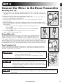
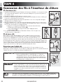
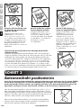
STEP 4
Connect the Wires to the Fence Transmitter
Boundary Wire (4A)
1. Run the Boundary Wire to the Fence Transmitter through a window, under a door, through a
crawl space vent, or any other appropriate available access. You can also drill a hole through
your wall.
2. Strip the ends of the Boundary Wire approximately 1.3 cm (1/2").
3. Insert the Boundary Wires into the Boundary Wire Terminals on the Fence Transmitter. Make sure
wires do not touch each other at the terminals.
4. Turn the Boundary Width Control knob to 10. This will set the Warning Zone at the
maximum width.
5. Plug the Power Adapter into the Power Socket and a working outlet. The Power Adapter comes
with the North American plug installed and additional plugs for the UK, Europe, and Australia. To
change the plug:
a. Push in the tab on the Power Adapter and remove the plug by sliding it off
as shown (4B).
b. Slide the proper plug for your electrical outlet onto the Power Adapter
as shown (4C).
6. The Power Light and Loop Indicator Lights should come on. If this does not
happen, see the “Troubleshooting” section.
Ground Wire (4D)
Proper grounding, although not necessary for the system to work, will help reduce the
chance of electrical surges causing damage to your Fence Transmitter and/or Power
Adapter. To ground your unit, you will need a solid (not stranded) Ground Wire (14
to 18 gauge insulated copper wire) and a ground rod with clamp, which may be obtained at most
electrical supply stores. Connect one end of the Ground Wire to the Ground Terminal located on the
Fence Transmitter and the other end of the Ground Wire to the ground rod. The ground rod must be
buried at least 90 cm (3 ft) into the ground and located as close as possible to the Fence Transmitter.
Fuse Protection (4E)
The Fence Transmitter is also equipped with a 250 volt, ½ amp fuse to protect the unit’s electronic
circuitry from electrical power surges. To locate the fuse, slide off the lid on the back of the Fence
Transmitter. A spare fuse is also provided.
• Do not install, connect, or remove your system during a lightning
storm. If the storm is close enough for you to hear thunder, it is close
enough to create hazardous surges.
• Risk of electric shock. Use the Fence Transmitter indoors in dry
location only.
If possible, DO NOT use an AC circuit protected with a Ground Fault Circuit
Interrupter (GFCI) or Residual Current Device (RCD). In rare cases, nearby
lightning strikes may cause the GFCI or RCD to trip. Without power your
dog may be vulnerable to escape. You will have to reset the GFCI or RCD to
restore power to the system.
For added protection, when unused for long periods of time or prior to thunderstorms, unplug from
the wall outlet and disconnect the loop boundary wires. This will prevent damage to the transmitter
due to surges.
Boundary Control Switch
Ground
Terminal
Boundary Wire
Terminals
Loop Indicator Light
Power Light
Power
Socket
Boundary Width
Control
4A
4B 4C
Ground
Wire
4D
FuseSpare Fuse
4E

12 www.petsafe.net
ENFRES
NL
IT
DE
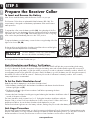
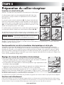
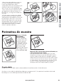
STEP 5
Prepare the Receiver Collar
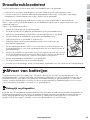
To Insert and Remove the Battery
Note: Do not install the battery while the Receiver Collar is on your pet.
This Receiver Collar utilizes a replaceable PetSafe
®
battery (RFA-188). This
unique battery is designed to make battery replacement easier and increase
water protection.
To activate the collar, insert the battery module (5A). Using the edge of the Test
Light Tool as shown, turn the battery clockwise until the vertical line on the battery
is pointed to the “ON” position (5B). If the PetSafe
®
Receiver Collar is not going
to be used on the pet immediately, leave it in the “OFF” position.
To remove the battery, turn the battery counter-clockwise using the edge of the Test
Light Tool as shown (5C, 5D).
Discharge all power by holding the Stimulation Level Button down until the light is
no longer illuminated. Replace with a new battery.
DO NOT attempt to cut into or pry open the battery.
Be sure to discard the used battery properly.
A replacement PetSafe
®
battery can be found at many retailers. Contact the Customer Care Centre or visit our website
at www.petsafe.net to locate a retailer near you.
Static Stimulation and Battery Test Feature
When the RFA-188 Battery Module is rst installed in the receiver, the red LED will ash the current stimulation level setting
(1 to 5). For the next 30 seconds, the receiver will monitor the battery status and will either ash the green LED once every 5
seconds to indicate a good battery, or ash the red LED once every 5 seconds to indicate a low battery condition. After the 30
second battery test period, the green LED will cease to ash if the battery is good. If the battery was low during the test period,
the red LED will continue to ash at a rate of 1 ash every 20 seconds to indicate a low battery condition. In this situation,
battery replacement is recommended.
To Set the Static Stimulation Level
Read all steps before attempting to set the Static Stimulation Level.
1.With the battery installed, press the Stimulation Level Button and release when the Receiver
Indicator Light lights red (5E).
2.The Receiver Indicator Light will emit a number of red ashes representing the Static
Stimulation Level (5F).
3.Increase the Static Stimulation Level by pressing and releasing the Stimulation Level Button within 5
seconds of the previous ashes.
The Static Stimulation Levels increase from 1 to 5. Pushing the Stimulation Level Button while the
Receiver Collar is on level 5 will cause the Receiver Collar to revert to level 1. Refer to the Function
and Response Table to choose the Static Stimulation level that best ts your pet.
The Receiver Indicator Light acts as a low battery indicator, ashing every 20 seconds when battery replacement is required.
Anti-Linger Prevention
The Anti-Linger Prevention feature keeps your dog from staying in the Warning Zone for long periods of time and draining the
Receiver Collar battery. Your dog will hear a warning tone when he reaches the Warning Zone. If your dog does not return to
the Pet Area after two seconds, he will receive a continuous Static Stimulation until he returns to the Pet Area.
5A 5B
5D
5C
5E
5F

13www.petsafe.net
EN
FR
ES
NL
IT
DE
Run Through Prevention
This system includes a unique “run-through” prevention so that your dog cannot escape the Pet Area without receiving an
increased level of Static Stimulation. The Receiver Collar automatically increases the Static Stimulation when your dog continues
more than 20% of the way through the pet fencing Boundary Width. For example, if the signal is detected 3 metres from
the wire and your dog enters the Static Stimulation Zone, this feature is activated when he is approximately 2.4 metres from
the Boundary Wire. Your dog will then receive a Static Stimulation that is at an increased level corresponding to the Static
Stimulation level setting on the Receiver Collar. The Receiver Collar is equipped to automatically increase the level of Static
Stimulation the longer your pet remains in the Static Stimulation Zone if the collar is set at level 2 or above.
Over Stimulation Protection
In the unlikely event that your pet “freezes” in the Static Stimulation Zone, this feature limits the Static Stimulation duration to a
maximum of 30 seconds. While the system locks out further Static Stimulation, the warning tone will continue until the pet leaves
the Static Stimulation Zone.
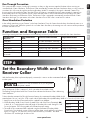
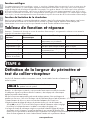
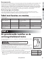
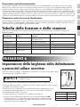
Function and Response Table
Note: Begin training with Static Stimulation Level 2 and only increase if your pet does not respond to the Static Stimulation.
Indicator Light
Response
Static Stimulation
Level
Receiver Collar Function Temperament of Pet
1 Red Flash 1 No Static Stimulation, Tone Only
2 Red Flashes 2 Low Static Stimulation Timid
3 Red Flashes 3 Medium Static Stimulation Timid or Average
4 Red Flashes 4 Medium High Static Stimulation Average or High Energy
5 Red Flashes 5 High Static Stimulation High Energy
Flashes 1 Red Flash every
20 seconds
Low Battery
STEP 6
Set the Boundary Width and Test the
Receiver Collar
With the Boundary Wire in place and properly connected, it is time to set the containment eld and
test the system.
The Receiver Collar should NOT be on your dog when
the system is tested.
Note: The Receiver Collar is waterproof, which can make the tone hard to hear.
The ashing Test Light when held to the Contact Points indicates the Receiver Collar is delivering
Static Stimulation.
To best utilize the automatic Run-Through Prevention feature, the containment Boundary Width should
extend at least 1.8 m to 3 m (6 ft to 10 ft) on each side of the Boundary Wire (total Boundary Width of 3.7 m to 6 m (12 ft to 20 ft).
1. Apply Power to the Fence Transmitter with the supplied Power Adapter.
2. Set the Boundary Width Control Switch (located on the side of the Fence Transmitter) (6A)
to the A, B, or C setting based on the total length of Boundary Wire used. Setting B is used
for most properties. The following table will indicate the proper setting.
3. The width of the containment eld is adjusted using the transmitter’s Boundary Width
Control knob. Turn the knob counter clockwise until the alarm sounds and the Loop Indicator
Light is no longer lit. Turn the knob clockwise and increase by 2 numbers. The alarm
should turn OFF and the light should turn ON.
6A
Amount of Wire Setting
Greater than 731 m
(2400 feet)
A
Up to 396 m
(1300 feet)
B
396 m to 731 m
(1300 feet to 2400 feet)
C

14 www.petsafe.net
ENFRES
NL
IT
DE
The receiver collar should not be on your dog when the system is tested. Your pet may
receive an unintended stimulation.
4. Place battery in Receiver Collar and turn ON. The Receiver Collar
will cycle through the Static Stimulation and Battery Status feature as
described in Step 5. To identify the Warning and Static Stimulation
Zones make sure the Receiver Collar is set at level 5 (see Step 5).
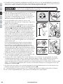
5. Test the Boundary Width of the system by selecting a section of
straight Boundary Wire that is at least 15 metres (50 feet) long. Start
inside the centre of the containment eld.
6. Place the Test Light Tool Contacts on the Contact Points on the
Receiver Collar (6B,6C). Hold the Receiver Collar at your dog’s neck
height with the Contact Points pointing up (6D) and the Stimulation
Level Button facing the Boundary Wire. Slowly walk toward the
Boundary Wire until you hear the warning tone (6E). When you hear
the warning tone, you have identi ed the Boundary Width distance
(Static Stimulation Zone).
Two seconds after the warning tone, the test light will begin to ash.
This ashing light can aid you in identifying the Boundary Width
should you have dif culty hearing the tone. To avoid having the
Receiver Collar go into Over Stimulation Protection mode, walk back
into the Pet Area until the beeping stops.
If the Receiver Collar does not beep at the desired range, adjust the
Boundary Width Control knob to obtain the desired range. Turning
the Boundary Width Control knob clockwise increases the Boundary
Width while turning it counterclockwise decreases it (6F). Repeat this
activity as needed until the Receiver Collar beeps between 1.8 m to
3 m (6 ft to 10 ft) from the Boundary Wire. If using a Double Loop
layout, you may need to increase the separation of the Boundary
Wire and/or increase the size of the Boundary Width to achieve the
desired range.
7. Test in a number of different locations around the containment area
until you are satis ed that the system is functioning properly.
8. Next, walk all around the Pet Area to ensure there are no areas
where the Receiver Collar may activate from signals coupled onto buried wires or cables. Test the collar in and around the
inside of the house as well. As mentioned, cable and wires from cable TV, electrical or telephone lines may conduct pet
fencing signals inside and outside the house that can activate the dog’s collar accidentally. While rare, if this occurs your
Boundary Wire is probably too close to these outside lines and should be moved or modi ed as shown in Figure 3A.
9. To test the run-through prevention feature, walk towards the Boundary Wire. The Receiver Collar should tone and the Test Light
should ash brighter as you enter the run-through area (6G).
If you are satis ed that your system is functioning properly, you are ready to start burying the Boundary Wire. If the Receiver
Collar did not beep or the Test Light did not ash, see the “Troubleshooting” section.
Test Light Contacts
6B
6C
Boundary
Wire
6E
6D
Boundary
Wire
6G
5
28
4
10
3
9
1
7
0
6
5
28
4
10
3
9
1
7
0
6
6F

15www.petsafe.net
EN
FR
ES
NL
IT
DE
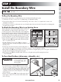
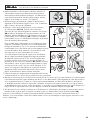
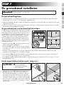
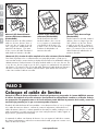
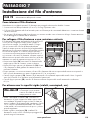
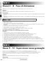
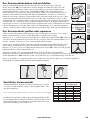
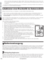
STEP 7
Install the Boundary Wire
Before you begin installing the Boundary Wire, unplug the Fence Transmitter power adapter from
the outlet.
To Bury the Boundary Wire
Burying the Boundary Wire is recommended to protect it and prevent disabling the system.
1. Cut a trench 2.5 cm to 7.6 cm (1 in to 3 in) deep along your planned boundary.
2. Place the Boundary Wire into the trench maintaining some slack to allow it to expand and contract with
temperature variations.
3. Use a blunt tool such as a wooden paint stick to push the Boundary Wire into the trench. Be careful not to damage the
Boundary Wire insulation.
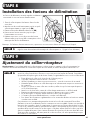
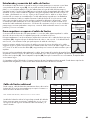
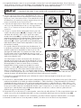
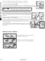
To Attach the Boundary Wire to an Existing Fence
The Boundary Wire of the Little Dog Deluxe In-Ground Fence™
can be attached to a chain link fence, split rail fence, or a
wooden privacy fence. The Boundary Wire can be attached as
high as needed. However, make sure the Boundary Width is set
at a high enough range for the pet to receive the signal. If using
a Double Loop with an existing fence at least 1.5 m (5 ft) tall,
run the Boundary Wire on top of the fence and return it on the
bottom of the fence to get the 1.5 m (5 ft) separation needed.
• Chain Link Fence (7A): Weave Boundary Wire through the
links or use plastic quick ties.
• Wooden Split Rail or Privacy Fence (7A):
Use staples to
attach Boundary Wire. Avoid puncturing the insulation of the
Boundary Wire.
• Double Loop with an Existing Fence: Run Boundary Wire on
top of the fence and return it on the bottom of the fence to get the 1.5 m (5 ft) separation needed.
• Gate (Single Loop) (7B):
Bury the Boundary Wire in the ground across the gate opening. Note: The signal is still active across
the gate. Your pet cannot pass through an open gate.
• Gate (Double Loop) (7B): Bury both Boundary Wires across the gate opening while keeping them at least
1.5 m (5 feet) apart.
To Cross Hard Surfaces (driveways, sidewalks, etc.)
Follow all safety instructions
for your power tools. Be
sure to always wear your
safety goggles.
• Concrete Driveway or Sidewalk (7C): Place the Boundary
Wire in a convenient expansion joint
or create a groove using
a circular saw and masonry blade. Place the Boundary Wire
in the groove and cover with an appropriate waterproo ng
compound. For best results, brush away dirt or other debris
before patching.
• Gravel or Dirt Driveway (7D): Place the Boundary Wire in
a PVC pipe or water hose to protect the Boundary Wire
before burying.
STAPLE WIRE TO FENCE
WEAVE WIRE INTO FENCE
STAPLE WIRE
TO FENCE
7A
(5 ft)
1.5 m
(5 ft)
1.5 m
SINGLE LOOP
DOUBLE LOOP
7B
7C
7D

16 www.petsafe.net
ENFRES
NL
IT
DE
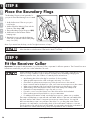
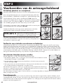
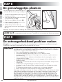
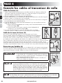
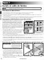
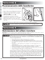
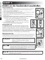
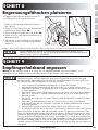
STEP 8
Place the Boundary Flags
The Boundary Flags are visual reminders for
your pet of where the Warning Zone is located.
1. Hold the Receiver Collar at your pet’s
neck height.
2. Walk towards the Warning Zone until the
Receiver Collar beeps (8A).
3. Place a Boundary Flag in the ground (8B).
4. Walk back into the Pet Area until the
beeping stops.
5. Repeat this process around the Warning
Zone until it is marked with Boundary Flags
every 3 m (10 ft).
Boundary
Wire
8B
8A
Note: If you cannot hear the beep, see the Test Light Instructions in Step 6.
To prevent an unintended stimulation, after the Boundary Flags have been placed, be sure to set the
Static Stimulation on the Receiver Collar back to level 1 Tone Only.
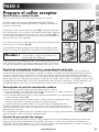
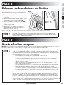
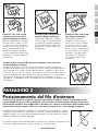
STEP 9
Fit the Receiver Collar
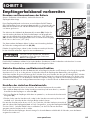
Important: The proper fit and placement of your Receiver Collar is important for effective operation. The Contact Points must
have direct contact with your pet’s skin on the underside of his neck.
Please read and follow the instructions in this manual. Proper fit of the collar is important. A collar
worn for too long or made too tight on the pet’s neck may cause skin damage. Ranging from
redness to pressure ulcers; this condition is commonly known as bed sores.
• Avoid leaving the collar on the dog for more than 12 hours per day.
• When possible reposition the collar on the pet’s neck every 1 to 2 hours.
• Check the fit to prevent excessive pressure; follow the instructions in this manual.
• Never connect a lead to the electronic collar; it will cause excessive pressure on the contacts.
• When using a separate collar for a lead, don’t put pressure on the electronic collar.
• Wash the dog’s neck area and the contacts of the collar weekly with a damp cloth.
• Examine the contact area daily for signs of a rash or a sore.
• If a rash or sore is found, discontinue use of the collar until the skin has healed.
• If the condition persists beyond 48 hours, see your veterinarian.
• For additional information on bed sores and pressure necrosis, please visit our website.
These steps will help keep your pet safe and comfortable. Millions of pets are comfortable while
they wear stainless steel contacts. Some pets are sensitive to contact pressure. You may find
after some time that your pet is very tolerant of the collar. If so, you may relax some of these
precautions. It is important to continue daily checks of the contact area. If redness or sores are
found, discontinue use until the skin has fully healed. You may need to trim the hair in the area of
the Contact Points. Never shave the dog’s neck; this may lead to a rash or infection.

17www.petsafe.net
EN
FR
ES
NL
IT
DE
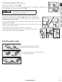
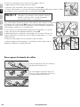
To assure a proper t, please follow these steps:
1.Turn the Receiver Collar battery to the OFF position.
2.Have your pet standing comfortably (9A).
3.Place the Receiver Collar on your pet so that the battery module is pointing down. Centre the Contact
Points underneath your pet’s neck, touching the skin (9B).
You may need to trim the hair in the area of the
Contact Probes. Never shave the dog’s neck; this
may lead to a rash or infection.
4. The Receiver Collar should fit snugly, yet loose enough to allow one finger to fit
between a Contact Point and your pet’s neck (9B). Allow your pet to wear the collar
for several minutes, then recheck the fit. Check the fit again as your pet becomes more
comfortable with the Receiver Collar.
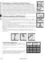
5. Once you are satisfied with the fit of the Receiver Collar then you may trim any excess
collar strap as follows (9C):
a. Mark the desired length of the Receiver Collar with a pen. Allow for growth if your pet
is young or grows a thick winter coat.
b. Remove the Receiver Collar from your pet and cut off the excess.
c. Before placing the Receiver Collar back onto your pet, seal the edge of the cut
collar by applying a flame along the frayed edge.
To Re-Thread the Collar
The slide buckle prevents the collar from
becoming loose around your pet’s neck.
The ridges must be facing up; the collar will slip if
it is not properly threaded.
9A
9B
9C
Slide Buckle
Ridges

18 www.petsafe.net
ENFRES
NL
IT
DE
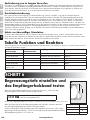
TRAINING GUIDE
Be Patient With Your Pet
Important: Proper training of your pet is essential to the success of the Little Dog Deluxe In-Ground Fence™ . Read this section
completely before beginning to train your pet. Remember that the Little Dog Deluxe In-Ground Fence™ is not a solid barrier.
• Have fun with your pet throughout the training process. Training should be fun, fair, rm and consistent.
• Train for 10 to 15 minutes at a time. Don’t try to do too much too quickly. More-frequent short sessions are better than less-
frequent longer sessions.
• If your pet shows signs of stress, slow down the training schedule, add additional days of training, or increase the amount of
play time with your pet in the Pet Area. Common stress signals include:
- Pet pulling on lead toward the house
- Ears tucked
- Tail down
- Body lowered
- Nervous / frantic movement or stiffening of pet’s body
• Your pet must be completely comfortable near the Boundary Flags at the end of every training session. Spend at least 5
minutes of “play time” at the completion of each session within 3 m (10 ft) of the Boundary Flags.
• Finish each training session on a positive note with lots of praise and play.
• Remove the Receiver Collar after each training session.
• Be sure to contain your pet by another means during the training period (e.g. pen, tie-out, lead, etc.).
• During training, if you need to take your pet out of the Pet Area, remove the Receiver Collar and either pick your pet up or put
him in the car to pass out of the Pet Area.
• Even if you think your pet is responding well to the training, complete the entire training. Reinforcement is important!
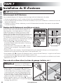
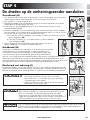
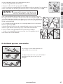
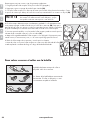
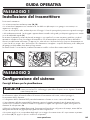
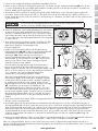
PHASE 1
Day 1 - Boundary Awareness
Perform three training sessions per day, each lasting 10 to 15 minutes.
Goal:
To have your pet learn that the Boundary Flags and warning beep from the Receiver Collar de nes the new Pet Area.
Setup:
Program the Static Stimulation Level on the Receiver Collar to Level 1 Tone Only training mode.
Put a separate non-metallic collar on your pet’s neck ABOVE the Receiver Collar and attach a lead.
Be sure the extra collar does not put pressure on the Contact Points.
Have tiny pieces of treats that your pet will nd desirable available.
Have your pet’s favourite play toy available.

19www.petsafe.net
EN
FR
ES
NL
IT
DE
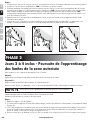
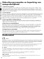
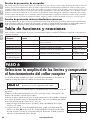
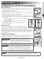
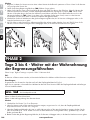
Steps:
1. Begin by walking your pet on a lead in the Pet Area. Calmly praise and talk to your pet.
2. Move toward the Boundary Flags (10A). Keep your mood happy.
3. With full control of your pet on a lead, walk to the ags. As your pet enters the Static Stimulation Zone, the Receiver Collar
will begin to beep (10B). Allow your pet to stay in the Static Stimulation Zone for up to 2 seconds then gently help him back
into the Pet Area (10C). Immediately praise and offer your pet a treat as he enters the Pet Area, even if you have helped with
the lead.
4. Repeat this process at the same Boundary Flag until your pet resists going into the Static Stimulation Zone.
5. Aim to master 3 to 4 Boundary Flags per session. Make this FUN! Praise if your pet quickly retreats or resists going into the
Static Stimulation Zone.
10A 10C10B
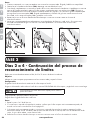
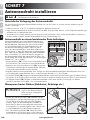
PHASE 2
Days 2 thru 4 - Continue Boundary
Awareness
Perform three training sessions per day, each lasting 10 to 15 minutes.
Goal:
To train your pet to stay in the Pet Area and respect the boundary.
Setup:
Program the Static Stimulation Level on the Receiver Collar to Level 2.
Put a separate non-metallic collar on your pet’s neck ABOVE the Receiver Collar and attach a lead.
Be sure the extra collar does not put pressure on the Contact Points.
Have tiny pieces of treats available.
Have your pet’s favourite play toy available.
Steps:
1. Repeat steps 1 thru 5 in Phase One.
2. If your pet does not respond to the Static Stimulation, con rm that the Receiver Collar is tting properly according to Step 9
on page 16.
3. If the Receiver Collar is tted properly and your pet does not respond to the Static Stimulation, increase the Static Stimulation
Level by 1. Watch for slight reactions at rst such as ears up, head turned, looking at the ground.
4. Stay at the same ag until your pet resists going into the Static Stimulation Zone.

20 www.petsafe.net
ENFRES
NL
IT
DE
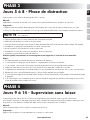
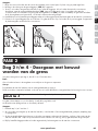
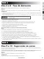
PHASE 3
Days 5 thru 8 - Distraction Phase
Perform three training sessions per day, each lasting 10 to 15 minutes.
Goal:
To train your pet to stay within the Pet Area with distractions outside of the Pet Area.
Setup:
• Program the Static Stimulation Level on the Receiver Collar to level 2 or higher depending on the reaction results from days 2
thru 4.
• Put a separate non-metallic collar on your pet’s neck ABOVE the Receiver Collar and attach a lead.
Be sure the extra collar does not put pressure on the Contact Points.
• Have tiny pieces of treats available.
• Have your pet’s favourite play toy available.
• Create distractions to tempt your pet to enter the Static Stimulation Zone,such as:
• Have a family member cross from inside the Pet Area to outside of it.
• Throw a ball or treat outside of the Pet Area.
• Have a neighbor walk their pet outside of the Pet Area.
• Gradually increase distraction level.
Never coax or call your pet out of the pet area.
Steps:
1. With full control of your pet on a lead, have the distraction presented.
2. If your pet does not move toward the distraction, praise and offer a treat.
3. If your pet does react to the distraction, allow him to go into the Static Stimulation Zone.
4. Help your pet back into the Pet Area if he does not turn back after 2 seconds.
5. Treat and praise your pet anytime he comes back into the Pet Area with or without help.
6. Repeat this process with other distractions. Use other family members during this process.
7. If your pet does not respond to the Static Stimulation, con rm that the Receiver Collar is tting properly according to Step 9
on page 16 .
8. If the Receiver Collar is tted properly and if your pet does not respond to the Static Stimulation, increase the Static
Stimulation Level by 1.
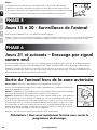
PHASE 4
Days 9 thru 14 - Off-lead Supervision
Training sessions should start at 10 to 15 minutes, gradually increasing to over an hour.
Your pet is ready for this step only when he clearly avoids the entire Static Stimulation Zone, regardless of any distractions or
temptations. During this step, do not leave your pet unattended.
Goal:
To give your pet free run of the Pet Area off the lead.
Setup:
Adjust the Receiver Collar to the permanent setting appropriate for your pet.
La page charge ...
La page charge ...
La page charge ...
La page charge ...
La page charge ...
La page charge ...
La page charge ...
La page charge ...
La page charge ...
La page charge ...
La page charge ...
La page charge ...
La page charge ...
La page charge ...
La page charge ...
La page charge ...
La page charge ...
La page charge ...
La page charge ...
La page charge ...
La page charge ...
La page charge ...
La page charge ...
La page charge ...
La page charge ...
La page charge ...
La page charge ...
La page charge ...
La page charge ...
La page charge ...
La page charge ...
La page charge ...
La page charge ...
La page charge ...
La page charge ...
La page charge ...
La page charge ...
La page charge ...
La page charge ...
La page charge ...
La page charge ...
La page charge ...
La page charge ...
La page charge ...
La page charge ...
La page charge ...
La page charge ...
La page charge ...
La page charge ...
La page charge ...
La page charge ...
La page charge ...
La page charge ...
La page charge ...
La page charge ...
La page charge ...
La page charge ...
La page charge ...
La page charge ...
La page charge ...
La page charge ...
La page charge ...
La page charge ...
La page charge ...
La page charge ...
La page charge ...
La page charge ...
La page charge ...
La page charge ...
La page charge ...
La page charge ...
La page charge ...
La page charge ...
La page charge ...
La page charge ...
La page charge ...
La page charge ...
La page charge ...
La page charge ...
La page charge ...
La page charge ...
La page charge ...
La page charge ...
La page charge ...
La page charge ...
La page charge ...
La page charge ...
La page charge ...
La page charge ...
La page charge ...
La page charge ...
La page charge ...
La page charge ...
La page charge ...
La page charge ...
La page charge ...
La page charge ...
La page charge ...
La page charge ...
La page charge ...
La page charge ...
La page charge ...
La page charge ...
La page charge ...
La page charge ...
La page charge ...
La page charge ...
La page charge ...
La page charge ...
La page charge ...
La page charge ...
La page charge ...
La page charge ...
La page charge ...
La page charge ...
La page charge ...
La page charge ...
La page charge ...
La page charge ...
La page charge ...
La page charge ...
La page charge ...
La page charge ...
La page charge ...
La page charge ...
La page charge ...
La page charge ...
La page charge ...
La page charge ...
La page charge ...
La page charge ...
La page charge ...
-
 1
1
-
 2
2
-
 3
3
-
 4
4
-
 5
5
-
 6
6
-
 7
7
-
 8
8
-
 9
9
-
 10
10
-
 11
11
-
 12
12
-
 13
13
-
 14
14
-
 15
15
-
 16
16
-
 17
17
-
 18
18
-
 19
19
-
 20
20
-
 21
21
-
 22
22
-
 23
23
-
 24
24
-
 25
25
-
 26
26
-
 27
27
-
 28
28
-
 29
29
-
 30
30
-
 31
31
-
 32
32
-
 33
33
-
 34
34
-
 35
35
-
 36
36
-
 37
37
-
 38
38
-
 39
39
-
 40
40
-
 41
41
-
 42
42
-
 43
43
-
 44
44
-
 45
45
-
 46
46
-
 47
47
-
 48
48
-
 49
49
-
 50
50
-
 51
51
-
 52
52
-
 53
53
-
 54
54
-
 55
55
-
 56
56
-
 57
57
-
 58
58
-
 59
59
-
 60
60
-
 61
61
-
 62
62
-
 63
63
-
 64
64
-
 65
65
-
 66
66
-
 67
67
-
 68
68
-
 69
69
-
 70
70
-
 71
71
-
 72
72
-
 73
73
-
 74
74
-
 75
75
-
 76
76
-
 77
77
-
 78
78
-
 79
79
-
 80
80
-
 81
81
-
 82
82
-
 83
83
-
 84
84
-
 85
85
-
 86
86
-
 87
87
-
 88
88
-
 89
89
-
 90
90
-
 91
91
-
 92
92
-
 93
93
-
 94
94
-
 95
95
-
 96
96
-
 97
97
-
 98
98
-
 99
99
-
 100
100
-
 101
101
-
 102
102
-
 103
103
-
 104
104
-
 105
105
-
 106
106
-
 107
107
-
 108
108
-
 109
109
-
 110
110
-
 111
111
-
 112
112
-
 113
113
-
 114
114
-
 115
115
-
 116
116
-
 117
117
-
 118
118
-
 119
119
-
 120
120
-
 121
121
-
 122
122
-
 123
123
-
 124
124
-
 125
125
-
 126
126
-
 127
127
-
 128
128
-
 129
129
-
 130
130
-
 131
131
-
 132
132
-
 133
133
-
 134
134
-
 135
135
-
 136
136
-
 137
137
-
 138
138
-
 139
139
-
 140
140
-
 141
141
-
 142
142
-
 143
143
-
 144
144
-
 145
145
-
 146
146
-
 147
147
-
 148
148
-
 149
149
-
 150
150
-
 151
151
-
 152
152


Petsafe PIG20-11041 Le manuel du propriétaire
- Catégorie
- S'occuper d'un animal
- Taper
- Le manuel du propriétaire
dans d''autres langues
- italiano: Petsafe PIG20-11041 Manuale del proprietario
- English: Petsafe PIG20-11041 Owner's manual
- español: Petsafe PIG20-11041 El manual del propietario
- Deutsch: Petsafe PIG20-11041 Bedienungsanleitung
- Nederlands: Petsafe PIG20-11041 de handleiding
Documents connexes
-
Petsafe HIG11-11052 Mode d'emploi
-
-
-
-
-
-
-
-
-
Autres documents
-
Dogtra 2000T series Le manuel du propriétaire
-
Guardian Wireless Pet Containment System Operating And Training Manual
-
SURE petcare iCWS Series Mode d'emploi
-
Ferplast 75091016 Manuel utilisateur
-
FORCLOVER CJW-PG6473 Manuel utilisateur
-
Num'axes Canifugue Pro Manuel utilisateur
-
Trixie 62815 Mode d'emploi
-
Kerbl 986080 SnailStop Starter Set Manuel utilisateur
-
Gallagher G50405 Manuel utilisateur
-