SWITEL SPF4763 Le manuel du propriétaire
- Taper
- Le manuel du propriétaire

Dépannage
moniteur
moniteur
moniteur
Des traces de doigts ou de la poussière sur la surface de la lentille peuvent
affecter l'exécution de la caméra. Evitez de toucher la surface de la lentille
avec les doigts.
En cas de mauvais signal ou d'interférence
Vérifiez que les commutateurs de canal sur la caméra et le sont
réglés sur le même canal.
Si un four micro-onde est utilisé entre la caméra et le moniteur, retirez le four
ou éteignez-le.
Vérifiez que la caméra et le sont à portée l'un de l'autre (portée
d'environ 300 pieds ; 100 mètres en ligne droite sans obstacle).
Si les étapes ci-dessus ne résolvent pas le problème, réglez la caméra et
le sur un autre canal.
Soin et entretien
Conservez toutes les parties et accessoires de l'appareil hors de portée des
enfants.
Des empreintes de doigt ou de la poussière sur l'objectif peuvent affecter la
performance de la caméra. Evitez de toucher la surface de l'objectif avec vos
doigts.
Si l'objectif venait à se salir, utilisez un souffleur pour souffler les saletés et
la poussière, ou un chiffon doux et sec pour essuyer l'objectif.
Le moniteur est prévu pour une utilisation à l'intérieur uniquement.
N'utilisez pas ou ne stockez pas milieu poussiéreux, humide, chaud ou très
froid.
N'essayez pas d'ouvrir le boîtier. Une manipulation effectuée par un
nonexpert peut endommager l'appareil.
Evitez de le faire tomber ou de lui faire subir des chocs importants.
Ne faîtes fonctionner ce produit qu'avec la source d'alimentation qui est
inclue et qui est fournie avec ses accessoires.
Ne surchargez pas les prises électriques ou les rallonges car cela pourrait
causer un incendie ou des chocs électriques.
N'oubliez pas que vous utilisez des fréquences radio publiques avec ce
système et que le son et la vidéo peuvent être transmis vers d'autres appareils
de réception 2,4 GHz. Des conversations, mêmes dans les pièces avoisinant
la caméra, peuvent être diffusées.
Pour protéger la confidentialité de votre maison, éteignez toujours la caméra
quand vous ne vous en servez pas.
Ce que vous avez
Une caméra
Un moniteur
Deux adaptateurs
Deux
Vis de fixation et chevilles de maçonnerie
Manuel de l'utilisateur
Moniteur
1.
2.
3. Bouton de sélection des canaux (Sélectionnez le canal en tournant le bouton
vers le numéro du canal que vous désirez configurer. Remarque: Vous
devez choisir le même canal sur la caméra et sur le récepteur.)
4.
5. Ecran Allumé/Eteint (L'écran peut être éteint lors d'une surveillance
uniquement audio.)
6. cran Allumé/Eteint
7. Bouton:
8. Contrôle d'alimentation/volume
9. Prise de l'adaptateur de courant 6V
10.
11.
12. Compartiment des piles
Caméra (Fig. 2)
1.
2. Desserrez la vis au-dessous du support avec un tournevis.
3. Faites tourner la caméra pour effectuer des ajustements.
4. Lorsque vous êtes satisfaits de la couverture de l'image, resserre la vis.
Remarque: Après l'ajustement de l'angle de vue, assurez-vous que le
corps de la caméra est fixé solidement au pivot du support. S'il est
lâche, utilisez une main pour maintenir le corps de la caméra et avec
l'autre main, utilisez des pinces pour serrer les surfaces plates sur le
pivot, faites tourner le pivot dans le sens horaire pour serrer. Voir Fig. 9.
moniteur
Alimentation
Le moniteur utilise soit 4 piles de taille AA (piles alcaline recommandées)
ou le courant CA normal.
Charger les piles
1. Ouvrez le compartiment des piles à l'arrière du moniteur. Voir la fig.
11.
2. Insérez 4 piles AA (suivez les signes plus (+) et moins (-) du diagramme
dans le compartiment des piles). Voir la fig. 11.
3. Refermez le compartiment des piles, et assurez-vous qu'il est bien
verrouillé.
Note: Ne mélangez jamais des piles usagées avec des piles neuves.
4. Allumez le moniteur. Ajustez le volume à un niveau confortable.
Utiliser l'alimentation CA
1. Branchez une extrémité de l'adaptateur d'alimentation fourni dans une
prise murale et l'autre extrémité au moniteur. Voir la fig. 10.
Note: Utilisez l'adaptateur étiqueté OUTPUT: 6V CC avec le
moniteur.
2. Allumez le moniteur. Ajustez le volume à un niveau confortable.
Définissez le même canal que sur la caméra en pressant le bouton CH.
Voir la fig. 12.
câble AV (audio/vidéo) (mini-RCA ou mini-Péritel)
Support de fixation
Ruban étanche
Figures des produits
(Fig. 1)
Antenne
Ecran LCD
Voyants d'indicateur de canaux
Voyants d'indicateur de E
Régler la luminosité
Connecteur d'entrée AV
Connecteur de sortie AV
1. Support de fixation
2. Vis de l'angle de fixation
3. Pivot
4. Voyants infrarouges (Huit voyants pour fournir une lumière infrarouge pour
la lumière nocturne)
5. Microphone
6. Corps de la caméra
7. Commutateur de sélection du canal
Configuration
Configuration de la caméra
Sélection des canaux
Choisissez le canal sur la caméra en faisant glisser les commutateurs à l'arrière
de la caméra, voir Fig. 3. (Retirez le couvercle en caoutchouc en bas de l'arrière
de la caméra et faites basculer les commutateurs avec un tournevis.)
Positionnement de la caméra
1. Faites deux trous à 86 mm de distance et alignés, là où la caméra doit
être installée.
2. Fixez la caméra au mur ou au plafond en utilisant les chevilles de
maçonnerie et les vis de fixation fournies. Voir Fig. 4, 6.
Remarque: Le support a un trou, vous pouvez faire passer le câble de
la caméra au travers du trou et l'insérer dans la fente à l'arrière du
support, puis fixez la caméra au mur. Voir Fig. 5.
3. Sélectionnez un emplacement approprié pour faire un trou d'entrée
pour le câble. Selon l'emplacement, ceci peut être fait dans le mur de
la maison ou au travers du cadre d'une porte ou d'une fenêtre.
4. Faites passer le câble au travers de son trou d'entrée. Il est
recommandé d'utiliser un sac plastique pour protéger la fiche à
l'extrémité du câble de la poussière et des dégradations. Tirez le reste
du câble à l'intérieur.
Alimentation
1. Connectez la prise de transformateur dans la prise d'entrée
d'alimentation du câble de la caméra. Vérifiez que les prises sont
enfoncées à fond.
2. Assurez-vous que les prises d'alimentation sont enfoncées à fond. Voir
Fig. 7.
Comment utiliser le ruban étanche
Après avoir connecté la prise de l'adaptateur d'alimentation à la prise
d'alimentation du câble de l'appareil photo, vous pouvez utiliser le ruban
étanche fourni pour éviter à l'entrée de l'humidité et de la poussière.
1. Enlevez le support du ruban adhésif et enroulez le ruban autour de la
prise et du réceptacle. Enroulez le ruban avec une tension suffisante
pour obtenir une couverture moulante de la surface.
2. Faites chevaucher le ruban d'au moins la moitié de sa largeur pour qu'il
adhère à lui-même, tout en retirant la doublure. Voir Fig. 7.
Optimisation
Ajustez l'angle de vision de la caméra selon les illustrations de la Fig. 8.
Configuration du
Sélection des canaux
Français
1
2
1
1
1
1
.
.
.
.
1
2
3
4
Care and Maintenance
Keep all parts and accessories out of young children's reach.
Fingerprints or dirt on the lens surface can adversely affect camera
performance. Avoid touching the lens surface with your fingers.
Should the lens become dirty, use a blower to blow off dirt and dust, or a soft,
dry cloth to wipe off the lens.
Do not attempt to open the case. Non-expert handling of the device may
damage the system.
Avoid dropping or strong shocks.
Operate this product using only the power supply included or provided as an
accessory.
Do not overload electrical outlets or extension cords. This can result in fire
or electric shocks.
Do remember that you are using public airwaves when you use the system
and that sound and video may be broadcasted to other 2.4 GHz receiving
devices. Conversations, even from rooms near the camera, may be
broadcasted. To protect the privacy of your home, always turn the camera off
when not in use.
Specifications
The receiver is for indoor use only. Do not use or store it in dusty, humid,
hot or very cold area.
English
What You Get
One camera
One monitor
Two power adapters
Two A/V (Audio/Video) Cables (mini-RCA or mini-Scart)
Mounting plate
Waterproof tape
Fixing screws and masonry plugs
This user's manual
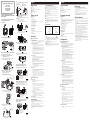
Product Layout
Monitor (Fig. 1)
1. Antenna
2. LCD screen
3. Channel selection button
4. Channel indicator LEDs
5. Screen ON/OFF (screen can be turned off for pure audio monitoring)
6. Screen ON/OFF indicator LED
7. Brightness adjustment control
8. Power/volume control
9. Power adapter jack
10. AV (Audio/Video) input jack
11. AV (Audio/Video) output jack
12. Battery compartment
Camera (Fig. 2)
1. Mounting bracket
2. Screw for fixing angle
3. Pivot
4. Infrared LEDs (Eight LEDs provide infrared light for night vision)
5. Microphone
6. Camera body
7. Channel selection switches
Setting Up
Setting up the camera
Select channels
Select the channel on the camera by sliding the slide switches on the back
of the camera, see Fig. 3. (Remove the rubber plug at the bottom of the
back of camera. Slide the switches by using a screwdriver.)
1. Drill two holes 86mm apart, at the camera mounting position.
2. Fix the camera to the wall or ceiling using the masonry plugs and fixing
screws supplied. See Fig. 4 and Fig 6.
Note: There is a hole on the bracket. Thread the cable from the camera
through the hole and insert the cable into the groove on the back of the
bracket, then fix the camera on to the wall. See Fig. 5.
3. Select a suitable location to drill a cable entry hole. Depending on the
location, this can be through the house wall or through a door or
window frame.
4. Push the cable through the cable entry hole. We recommend using a
plastic bag to protect the plug on the end of the cable from dust and
damage. Pull the rest of the cable inside.
Power supply
1. Connect the plug of the power adapter with the Power In socket of the
cable from the camera. Make sure power plugs are pushed all the way in.
2. Plug the AC adapter into a wall outlet. See Fig. 7.
How to use the waterproof tape
After connecting the plug of the power adapter to the Power In socket of
the camera, use the provided waterproof tape to prevent moisture and dirt
getting inside.
1. Remove the release liner and wrap the waterproof tape in a spiral
around the plug and socket. Wrap the tape with enough tension to
obtain conformability on the surface.
2. Overlap by at least half the width of the tape so it bonds to itself, while
removing the release liner. See Fig. 7.
Fine tuning
1. Adjust the camera's viewing angle according to the illustrations of Fig. 8.
2. Loosen the screw on the bottom of bracket by using a screwdriver.
3. Rotate the camera to make adjustments.
4. When satisfied with the picture coverage, retighten the screw
Note: After adjusting the viewing angle, make sure the camera body is
attached to the pivot of the bracket tightly. If it is loose, use one hand
to hold the camera body steady, and with the other hand, use pliers to
pinch the flat surfaces on the pivot. Swivel the pivot clockwise to
tighten. See Fig. 9.
Setting up the monitor
Power supply
The monitor uses either 4 AA-size batteries or household AC current.
Battery operation
1. Open the battery compartment cover on the bottom of the monitor.
See Fig 11.
2. Insert 4 AA-size batteries, making sure to match the positive (+) and
negative (-) ends to the diagram inside the battery compartment. See
Fig 11.
3. Close the battery compartment cover. Make sure the battery
compartment cover is locked securely.
Note : Never mix old batteries with new ones.
4. Turn the monitor on. Adjust the volume to a comfortable level.
Mains operation
1. Plug one end of the provided power adapter into a wall outlet and the
other end into the back of the monitor. See Fig 10. Note: Use the
adapter labeled OUTPUT: 6V DC with the monitor.
2. Turn the monitor on. Adjust the volume to a comfortable level.
Select channels
Set the same channel as camera by pressing the CH button. See Fig. 12.
Troubleshooting
If the signal is poor, or there is interference
Check that the channel switches on the camera and the receiver are set to the
same number.
If there is a microwave oven in use in the path between the camera and
monitor, remove the microwave oven or turn it off.
Make sure the camera and the monitor are within range of each other (range
of approximately 300 feet; 100 meters in a clear line of sight).
If the above steps don't help, set both the camera and monitor to other
channels.
Positioning the camera
Product Layout/Disposition du produit/Aspecto del producto
/Produkt-Layout/Struttura del prodotto
Monitor/Moniteur
October 2005
P/N: 408-000341-01
Figures and Quick Guide/
/
Figures et guide rapide
Figuras y Guía Rápido/Abbildungen und Schnellanleitung
/Figure e guida rapida
User's Manual
Manuel d'utilisation
Manual del Usuario
Benutzerhandbuch
Manuale utente
2
1.4
Fig. 2
1.4
Specifications subject to change without notice
Camera
Frequency 2.4 Ghz
Antenna Built-in omni-directional antenna
Channel 3 selectable channels
A/V mod/demod. method FM
Image Sensor Color CMOS image sensor
Effective pixels EIA: 510 (H) x 492 (V);
CCIR: 628 (H) x 582 (V)
Lens f 5.6mm, F 1.8
Dimensions 10.5(W) x 13(H) x 11.5(D) cm;
(4.1 x 5.1 x 4.5 inches) With
mounting bracket
Weight 300g (10.6 ounces)
Power DC 9V, 500mA
Operating temperature -10 ~ 40 (14 ~ 104 )
Camera/CCaméra/ ámara/Kamera/Videocamera
2
0678
FCC Statement
This equipment has been tested and found to comply with the limits for a Class B digital device, pursuant to Part 15 of the FCC Rules.
These limits are designed to provide reasonable protection against harmful interference in a residential installation. This equipment
generates, uses and can radiate radio frequency energy and, if not installed and used in accordance with the instructions, may cause
harmful interference to radio communications. However, there is no guarantee that interference will not occur in a particular installation.
If this equipment does cause harmful interference to radio or television reception, which can be determined by turning the equipment off
and on, the user is encouraged to try to correct the interference by one or more of the following measures:
Reorient or relocate the receiving antenna
Increase the separation between the equipment and receiver
Connect the equipment into an outlet on a circuit different from that to which the receiver is connected
Consult the dealer or an experienced radio/TV technician for help
FCC Label Compliance Statement:
This device complies with Part 15 of the FCC Rules. Operation is subject to the following two conditions: (1) this device may not cause
harmful interference, and (2) this device must accept any interference received, including interference that may cause undesired operation.
Note: The manufacturer is not responsible for any radio or TV interference caused by unauthorized modifications to this equipment.
Such modifications could void the user's authority to operate the equipment.
7
1
2
4
5
6
3
Fine Tuning/Ajustement/Ajuste Fino/Ausrichtung/Sintonia fine
1
Mounting on a ceiling/Fixation à un plafond/Montaje en el techo
/Befestigung an einer decke/montaggio a soffitto
86mm
Fig. 6
Setting up the Camera/Installer la caméra
/Configuración de la cámara/Einrichten der Kamera
/Installazione della videocamera
1 2 3 4
Channel 1
Channel 2
Channel 3
Fig. 3
Select Channels/Sélection des canaux/Selección de Canales
/Auswahl von Kanälen/Selezione dei canali
1.1
Positioning the camera/Positionnement de la caméra
/Montaje de la cámara/Befestigung der Kamera
/Posizionamento della telecamera
86
m
m
Fig. 4
Fig. 5
Remove the seal by using a screwdriver to push it.
/Retirez le cache en utilisant un tournevis pour le
pousser.
/Tire del precinto con un destornillador para sacarlo.
/Entfernen Sie das Siegel, indem Sie es mit einem
Schraubenzieher hereindr ken.
/Per rimuovere il fermo, fare pressione con un
cacciavite.
üc
Mounting on a wall/Fixation sur un mur/Montaje en la pared
/Befestigung an einer wand/Montaggio a parete
1.2
Power Supply/Alimentation/Alimentación/Stromversorgung
/Alimentazione elettrica
Fig. 7
Cable Entry Hole
/
/Agujero de Entrada del Cable
/Kabelloch
/Foro d'ingresso del cavo
Trou d'entrée du câble
Release Liner
/Doublure
/Revestimiento protector
/Klebebandstreifen
/Adesivo fissante
Waterproof Tape
/Ruban étanche
/Cinta impermeable
/Wasserdichtes Klebeband
/Nastro resistente all'acqua
1.3
Setting Up/Installation/Configuración/Einrichten/Installazione
2.4 GHz Wireless PC Surveillance System
2.1
Power Supply/Alimentation/Alimentación/Stromversorgung
/Alimentazione
Longitudinal turn (Tilt)
/Rotation longitudinale (inclinaison)
/Giro longitudinal (Inclinación)
/Vertikales Drehen (Kippen)
/Rotazione longitudinale (Inclinazione)
Horizontal turn (Pan)
/Rotation horizontale (panoramique)
/Giro Horizontal (Panorámica)
/Horizontales Drehen (Schwenken)
/Rotazione orizzontale (Panoramica)
Fig. 8
Fig. 9
Setting up the monitor/Configurazione du
/Instalación el monitor/Einrichten des Monitors
/Installazione del monitor
moniteur
Fig. 10
2.1
Fig. 12
1.3
Select Channels/Sélection des canaux/Seleccionar Canales
/Die Kanäle wählen/Selezionare I canali
2.
2
Fig. 11
2.
2
2.1
2.2
Fig. 1
1
2
3
4
5
6
9
7
10
12
8
11
1
2
3
2
1
Loading Batteries/Charger les piles/Inserción de las pilas
/Einlegen der Batterien/Inserimento delle batterie
Using AC Power/Utiliser l'alimentation CA
/Conexión del suministro de corriente alterna
/Anschließen an den Netzstrom/Utilizzo dell'alimentazione CA
Other Applications O/Autres applications/ tros usos
/Weitere Anwendungsbereiche/Altre applicazioni
Video input/Entree visuelle/Entrada video/Videoinput/Video input
Scart Cable for PAL System
/Câble péritel pour système PAL
/Cable tipo Scart para Sistema PAL
/Scart-Kabel für PAL-System
/Cavo scart per standard PAL
DVD/VCD Player
OUT
VIDEO
AUDIO
IN
Fig. 14
Fig. 13
2.
3
Audio Only/Audio seulement/Solamente Audio/Nur Audio
/Solo Audio
1
1.1
1.2
AV Connection - for TV with AV Input Jacks
/Connexion AV pour les téléviseurs avec des prises d'entrée AV
/Conexión AV - para TV con enchufes hembra de entrada de AV
/AV-Anschluss für Fernseher mit AV-Input-Buchsen
/Collegamento AV per televisori provvisti di prese d'ingresso AV
IN
TV
VIDEO
AUDIO
IN
Scart Cable for PAL System
/Câble péritel pour système PAL
/Cable tipo Scart para Sistema PAL
/Scart-Kabel für PAL-System
/Cavo scart per standard PAL
Fig. 15
Scart Cable for PAL System
/Câble péritel pour système PAL
/Cable tipo Scart para Sistema PAL
/Scart-Kabel für PAL-System
/Cavo scart per standard PAL
DVD/VCD Player
OUT
VIDEO
AUDIO
IN
Fig. 16
Recording on a VCR/Enregistrement sur un magnétoscope
/Grabar con una VCR/Aufnahme auf einen Videorecorder
/Registrazione su un VCR
Monitor
Frequency 2.4 GHz
Channel 3 selectable channels
A/V mod/demod. method FM
Display 3.5 inch LCD monior
Effective pixels
H: 300 lines
Sound max. output 800mW
Dimensions 14.2(W) x6.9(H) x 11.2(D) cm
Weight 385g without batteries
Power DC 6V, 1000mA
or 4 AA-size batteries
Operating temperature 0 ~ 40 (32 ~ 104 )
EIA: 320(H) x 240(V)
La page charge ...
-
 1
1
-
 2
2


SWITEL SPF4763 Le manuel du propriétaire
- Taper
- Le manuel du propriétaire
dans d''autres langues
- italiano: SWITEL SPF4763 Manuale del proprietario
- English: SWITEL SPF4763 Owner's manual
- español: SWITEL SPF4763 El manual del propietario
- Deutsch: SWITEL SPF4763 Bedienungsanleitung
Documents connexes
-
SWITEL O6LTTA-35T Manuel utilisateur
-
-
-
-
-
-
-
