La page est en cours de chargement...
La page est en cours de chargement...

4
■ Please keep original packaging of this article, so that it may be
used for transport at a later date, if necessary.
■ For technical reasons, we reserve the right to carry out prelimi-
nary assembly work (e.g. addition of tubing plugs).
Please, use suitable supporting material (such as packing
material, polystyrene or similar material) for this assembly
step in order to avoid a scratching or damaging of the hou-
sing.
If the computer is too faint to read or disappears complete-
ly, the batteries must be changed. The computer requires
two batteries. They are replaced as follows:
■ Remove the lid of the battery compartment and replace
the batteries with two fresh ones of type AA 1,5 V.
■ Ensure that the batteries are inserted as indicated in the
battery compartment.
■ Should the wrong figures be indicated when the com-
puter is switched onagain, disconnect the battery and
reconnect it immediately.
Important: Do not dispose of used batteries along with household
waste.
Spent batteries are not covered by the guarantee.
List of spare parts
When ordering spare parts, always state the full article number,
spare-part number, the quantity required and the inspection num-
ber stamped on the back.
Example order: Art. no. 7985-900 / spare-part no. 33100100/
2 pieces / inspection no. ...
Important: spare part prices do not include fastening material; if
fastening material (bolts, nuts, washers etc.) is required, this
should be clearly stated on the order by adding the words „with
fastening material“.
KETTLER GB Ltd. · Kettler House, Merse Road · North Moons Moat · Red-
ditch, Worcestershire B98 9HL
KETTLER International Inc. · 1355, London Bridge Road · USA-Virginia
Beach, Virginia 23450
www.kettler.net
A
B
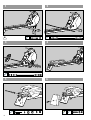
Instructions for Assembly
■ Ensure that you have received all the parts required (see check
list) and that they are undamaged. Should you have any cause
for complaint, please contact your KETTLER dealer.
■ Before assembling the equipment, study the drawings carefully
and carry out the operations in the order shown by the dia-
grams. The correct sequence is given in capital letters.
■ Please note that there is always a danger of injury when wor-
king with tools or doing manual work. Therefore please be ca-
reful when assembling this machine.
■ Ensure that your working area is free of possible sources of
danger, for example don’t leave any tools lying around. Al-
ways dispose packaging material in such a way that it may not
cause any danger. There is always a risk of suffocation if child-
ren play with plastic bags!
■ The equipment must be assembled with due care by an adult
person. If in doubt call upon the help of a second person, if pos-
sible technically talented.
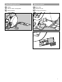
■ The fastening material required for each assembly step is sho-
wn in the diagram inset. Use the fastening material exactly as
instructed. The required tools are supplied with the equipment.
■ Bolt all the parts together loosely at first, and check that they
have been assembled correctly. Tighten the locknuts by hand un-
til resistance is felt, then use spanner to finally tighten nuts com-
pletely against resistance (locking device). Then check that all
screw connections have been tightened firmly. Attention: once
locknuts have been unscrewed they no longer function correctly
(the locking device is destroyed), and must be replaced.
Pour votre sécurité
■ Rameur ne doit être utilisée que pour les fins auxquelles elle est
destinée, c'est-à-dire pour l'entraînement des adultes.
■ Tout autre emploi est interdit, voire dangereux. Le fabricant ne
pourra être rendu responsable de dommages causés par l'em-
ploi inadéquat de l'appareil.
■ Vous vous entraînez avec un appareil dont la technique et la
sécurité correspondent aux exigences modernes. Les sources
possibles de danger qui pourraient entraîner des blessures ont
été soit supprimées, soit sécurisées.
■ L´appareil est conforme à la classe H de la norme EN 957 et
convient donc pour soins thérapeutiques.
■ Les réparations inadéquates et les modifications apportées à la
construction de l'appareil (démontage des pièces d'origine,
montage de pièces non autorisées, etc.) peuvent entraîner des
risques imprévus pour l'utilisateur.
■ Les composants endommagés peuvent affecter votre sécurité et
la durée de vie de l'appareil. On remplacera donc sans tarder
les composants usés ou endommagés et on interdira l'emploi
de l'appareil aussi longtemps qu'ils n'auront pas été rempla-
cés. N'utiliser que des pièces de rechange KETTLER d'origine.
■ On cas de doute, on est prié de s'adresser à son concession-
naire KETTLER.
■ En cas d'entraînement régulier et intensif, il y a lieu de contrô-
ler, tous les mois ou tous les 2 mois, toutes les pièces de l'ap-
pareil et en particulier les vis et les écrous.
■ Attirer l'attention des personnes présentes, surtout des enfants,
sur les dangers qu'ils courent pendant les exercices.
■ Avant de commencer, consulter son médecin traitant pour s'as-
surer que l'entraînement avec l'appareil n'est pas nuisible à la
santé. Son diagnostic devrait servir de base pour la compositi-
on de son programme de travail. Un entraînement exagéré ou
mal organisé peut être nuisible à la santé.
Lire attentivement les présentes instructions avant le montage et la première utilisation de l'appareil. Elles contiennent des renseigne-
ments importants relatifs à la sécurité des personnes ainsi qu'à l'emploi et à l'entretien du rameur. Conserver soigneusement les dites
instructions pour d'éventuels renseignements ainsi que pour effectuer l'entretien de l'appareil ou commander des pièces de rechange.
Instructions de montage
F

8
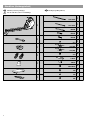
Checkliste (Packungsinhalt)
Checklist (contents of packaging)
Liste de vérification (contenu de l’emballage)
Checklijst (verpakkingsinhoud)
GB
F
NL
13x410mm
13x310mm
M6x90
M8x45
M5x40
ø12
ø16 (M6)
ø25
110mm
40mm
ø20x10mm
1
2
1
1
2
4
2
2
2
4
1
1
1
1
1
1
1
1
1
M8
M5
M6
1
1
ø16 (M8)
2
ø16
ø6,3
ø16
ø8,3

9
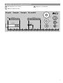
Messhilfe für Verschraubungsmaterial
Measuring help for screw connections
Gabarit pour système de serrage
Meethulp voor schroefmateriaal
GB
F
NL
0102030405060708090100 110 120 130 140 150 160 170
M5x40
M8x40
M8
ø22
ø16
ø12
M6
M5
ø3,9x13
Beispiele Examples Examples Bij voorbild
M5x40

10
5 6
3
4
M6x90
ø16
1
2
M6
ø20x10mm
M5
ø12
M5x40
ø16
M8x45
ø25
ø16
ø16
A
ø13x310mm110mm 110mm M8M8
ø25
ø25
ø13x410mm40mm 40mm M8M8

11
Handhabungshinweis
Handling
Indications relatives à la manipulation
Bedieningsinstrukties
GB
F
NL
Batteriewechsel
Battery change
Changement de piles
Vervanging van de batterijen
GB
F
NL

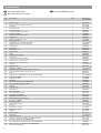
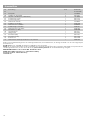
Teil Bezeichnung Stück Ersatzteil-Nr.
Nr. für 7985-600
Ersatzteilliste
1 Gehäuseeinheit 1 94314098
2 Bowdenzug mit Verstellhebel (montiert) 1 94314107
3Drehknopf 1 70127080
4Verstellrad (links) 1 70127500
5 Sicherungsscheibe 1 97200358
6 Sechskantschraube M8x145mm 1 10205145
7 Stopfen für ø42mm 2 10100079
8 Distanzrohr ø10x0,9x22,5mm 1 97200537
9Trägerblech 1 97200036
10 Zeiger für Cockpit (0 – 10) 1 91170207
11 Befestigungswinkel 1 97201826
12 Magnethalter mit 5 Magnetsegmentteilen 1 91170364-40
13 Magnetsegmentteil mit zwei Magneten 5 67000170
14 Verstell-Lasche 1 97200045
15 Pendelhalter 1 97201825
16 Magnet M 3101 1 67000146
17 Seilrolle Nr. 4 3 98585016
18 Lasche 1 97200249
19 Zugfeder für Umlenkung 1 25605910
20 Seilrolle Nr. 1 1 98585018
21 Sechskantschraube M8x140mm 1 10206086
22 Distanzrohr ø13x2,4x33,5mm 1 97200589
23 Distanzrohr ø13x2,4x72,5mm 1 97200591
24 Standfuss 1 91210323-40
25 Bodenschoner 1 70132175
26 Tragbalken 1200mm 1 91210356-40
27 HD-Distanzröhrchen ø20x6,4x10mm/Sitzanschlag 4 10108032
28 Schwungradeinheit (kpl. montiert) mit Seilen 1 94602267
29 Buchse 1 70132695
30 Griffrohr (kpl. mit Griffschlauch und Stopfen für ø25mm) 1 91210360-40
31 Griffschlauch 400mm 1 10118010
32 Stopfen für ø25mm 2 10100030
33 Lagerblech 1 97200046
34 Filzzuschnitt 20x15x4mm (selbstklebend) 2 12510024
35 Geschwindigkeitsaufnahme M3136 1 67000153
36 Zugfeder 1 25605973
37 Seilabdeckung 1 94314109
38 Batteriehalter 1 67000145
39 Batteriefachdeckel 1 70126674
40 Seitenverkleidung (rechts) 1 70132186
41 Seitenverkleidung (links) 1 70132187
42 MITTO-Plastic-Schraube 4x35 4 10224072
43 Elektronikaufsatz für Verkleidung 1 70132649
44 Computer ST 2500-4 1 67000545
45 Befestigungswinkel 1 97201827
46 Spreizniet ø6x9,5mm 8 10418503
47 Bodenrohr 1 91111287-40
48 Rollenschoner (rechts) 1 91170387
49 Rollenschoner (links) 1 91170388
50 Trittplatte 1 94314110
51 Abschlusskappe 1 70132156
52 Fahrwagen 1 91210358-40
53 Sitz für Rudergerät 1 72591160
54 Laufrolle für Fahrwagen (BITTE ALS SATZ BESTELLEN) 4 94313784
55 Gleitbuchse (BITTE ALS SATZ BESTELLEN) 4 70132682
56 Bolzen M8x42mm/SW15 (BITTE ALS SATZ BESTELLEN) 4 11300087
57 Hülse ø16x1,5x12,5 (BITTE ALS SATZ BESTELLEN) 4 97200579
58 Rollsitzunterverkleidung 1 70132176
12
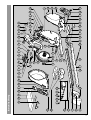
Spare parts drawing and list
Dessin et liste des pièces de rechange
Reserveonderdeeltekening en -lijst
GB
F
NL

13
119445
52
3 10 6 7 71 43 30 31 32
18 15 35 33
73
1
40
66
484768 50 654967372551
24
27
58
53
63 41
54 55 57 4656
26 39 38
14281213
17
5
44
28 17
64
19
36
21
22
20
23
5960
34
61
16
66
72
29
42
62 74
75
Ersatzteilzeichnung
La page est en cours de chargement...

15
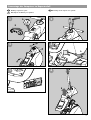
Demontage des Computers im Reparaturfall
Detaching computer for repairs
Démontage de l’ordinateur pour réparation
Demontage van de computer voor reparatie
GB
F
NL
A
A
B
B
A
B
12
34
56

docu 318e/08.02
Bei Reklamationen bitte diese Kontrollnummer angeben.
In case of complaint, please state this control number.
En cas de réclamation, priére de mentionner ce numéro de contrôle.
Bij reclamaties dit controlenummer vermelden.
D
GB
F
NL
-
 1
1
-
 2
2
-
 3
3
-
 4
4
-
 5
5
-
 6
6
-
 7
7
-
 8
8
-
 9
9
-
 10
10
-
 11
11
-
 12
12


Kettler Coach 07985-600-690 Le manuel du propriétaire
- Taper
- Le manuel du propriétaire
dans d''autres langues
Documents connexes
-
Kettler ERGOCOACH Le manuel du propriétaire
-
-
-
-
-
-
-
-
-
