Mitsubishi Electronics USA MLZ-KP09NA Le manuel du propriétaire
- Catégorie
- Climatiseurs split-system
- Taper
- Le manuel du propriétaire
Ce manuel convient également à

CEILING CASSETTE TYPE AIR CONDITIONERS
MLZ-KP09NA MLZ-KP12NA MLZ-KP18NA
Français
Español
English
INSTALLATION MANUAL
For INSTALLER
• Thismanualonlydescribestheinstallationofindoorunit.
Wheninstallingtheoutdoorunit,refertotheinstallationmanualofoutdoorunit.
NOTICE D’INSTALLATION
POUR L’INSTALLATEUR
• Cettenoticenedécritquel’installationdel’unitéinterne.
Pourl’installationdel’unitéexterne,sereporteràlanoticed’installationdel’appareil.
MANUAL DE INSTALACIÓN
PARA EL INSTALADOR
• Enestemanualsólosedescribelainstalacióndelaunidadinterior.
Parainstalarlaunidadexterior,consulteelmanualdeinstalacióndedichaunidad.
RG79Y948H01_en.indd 1 2018/01/23 11:41:53

En-1
1-1. THE FOLLOWING SHOULD ALWAYS BE OBSERVED FOR SAFETY
• Besuretoread“THEFOLLOWINGSHOULDALWAYSBEOBSERVEDFORSAFETY”beforeinstallingtheairconditioner.
• Besuretoobservethewarningsandcautionsspeciedhereastheyincludeimportantitemsrelatedtosafety.
• Afterreadingthismanual,besuretokeepittogetherwiththeOPERATINGINSTRUCTIONSforfuturereference.
• Pleasereporttoyoursupplyauthorityorobtaintheirconsentbeforeconnectingthisequipmenttothepowersupplysystem.
Required Tools for Installation
■ Do not install the unit by yourself (user).
Incompleteinstallationcouldcausereorelectric
shock,injuryduetotheunitfalling,orleakage
of water. Consult the dealer from whom you
purchasedtheunitoraqualiedinstaller.
■ Perform the installation securely referring
to the installation manual.
Incompleteinstallationcouldcausereorelectric
shock,injuryduetotheunitfalling,orleakageof
water.
■ When installing the unit, use appropriate
protective equipment and tools for safety.
Failuretodosocouldcauseinjury.
■ Install the unit securely in a place which
can bear the weight of the unit.
Iftheinstallationlocationcannotbeartheweight
oftheunit,theunitcouldfallcausinginjury.
■ Electrical work should be performed by a
qualied, experienced electrician, accord-
ing to the installation manual. Be sure to
use an exclusive circuit. Do not connect
other electrical appliances to the circuit.
Ifthecapacityofthepowercircuitisinsufcient
or there is incomplete electrical work, itcould
resultinareoranelectricshock.
■ Ground the unit correctly.
Donotconnectthegroundtoagaspipe,water
pipe,lightningrodortelephoneground.Defective
groundingcouldcauseelectricshock.
■ Do not damage the wires by applying
excessive pressure with parts or screws.
Damagedwirescouldcausereorelectricshock.
■ Be sure to cut off the main power in case of
setting up the indoor P.C. board or wiring
works.
Failuretodosocouldcauseelectricshock.
■ Use the specied wires to connect the
indoor and outdoor units securely and
attach the wires rmly to the terminal block
connecting sections so the stress of the
wires is not applied to the sections. Do not
extend the wires, or use intermediate con-
nection.
Incompleteconnectingandsecuringcouldcause
re.
■ Do not install the unit in a place where
inammable gas may leak.
Ifgasleaksandaccumulatesintheareaaround
theunit,itcouldcauseanexplosion.
■ Do not use intermediate connection of the
power cord or the extension cord and do
not connect many devices to one AC outlet.
Itcouldcauseareoranelectricshockdueto
defectivecontact,defectiveinsulation,exceeding
thepermissiblecurrent,etc.
■ Be sure to use the parts provided or speci-
ed parts for the installation work.
Theuseofdefectivepartscouldcauseaninjury
or leakage of water due to a re, an electric
shock,theunitfalling,etc.
■ When plugging the power supply plug into
the outlet, make sure that there is no dust,
clogging, or loose parts in both the outlet
and the plug. Make sure that the power
supply plug is pushed completely into the
outlet.
Ifthereisdust,clogging,orloosepartsonthe
powersupplyplugortheoutlet,itcouldcause
electricshockorre.Ifloosepartsarefoundon
thepowersupplyplug,replaceit.
■ Attach the electrical cover to the indoor
unit and the service panel to the outdoor
unit securely.
Iftheelectricalcoveroftheindoorunitand/orthe
servicepaneloftheoutdoorunitarenotattached
securely, it couldresultin a reor an electric
shockduetodust,water,etc.
■ When installing, relocating, or servicing
the unit, make sure that no substance
other than the specied refrigerant (R410A)
enters the refrigerant circuit.
Anypresenceofforeignsubstancesuchasair
cancauseabnormalpressureriseandmayresult
inexplosionorinjury.Theuseofanyrefrigerant
otherthanthatspeciedforthesystemwillcause
mechanicalfailure,systemmalfunction,orunit
breakdown.Intheworstcase,thiscouldleadto
aseriousimpedimenttosecuringproductsafety.
■ Do not discharge the refrigerant into the
atmosphere. Check that the refrigerant gas
does not leak after installation has been
completed. If refrigerant leaks during instal-
lation, ventilate the room.
Ifrefrigerantcomesincontactwithare,harmful
gascouldbegenerated.
Ifrefrigerantgasleaksindoors,andcomesinto
contact with the ameof afan heater,space
heater,stove,etc.,harmfulgaseswillbegener-
ated.
■ Use appropriate tools and piping materials
for installation.
ThepressureofR410Ais1.6timesmorethan
R22.Notusingappropriatetoolsormaterialsand
incompleteinstallationcouldcausethepipesto
burstorinjury.
■ When pumping down the refrigerant, stop
the compressor before disconnecting the
refrigerant pipes.
Iftherefrigerant pipes are disconnected while
thecompressorisrunningandthestopvalveis
open,aircouldbedrawninandthepressurein
therefrigerationcyclecouldbecomeabnormally
high.Thiscouldcausethepipestoburstorinjury.
■ When installing the unit, securely connect
the refrigerant pipes before starting the
compressor.
Ifthecompressorisstartedbeforetherefrigerant
pipesareconnectedandwhenthestopvalveis
open,aircouldbedrawninandthepressurein
therefrigerationcyclecouldbecomeabnormally
high.Thiscouldcausethepipestoburstorinjury.
■ Fasten a are nut with a torque wrench as
specied in this manual.
Iffastenedtootight,aarenutmaybreakafter
alongperiodandcauserefrigerantleakage.
■ The unit shall be installed in accordance
with national wiring regulations.
■ Do not use means to accelerate the defrost-
ing process or to clean, other than those
recommended by the manufacturer.
■ The appliance shall be stored in a room
without continuously operating ignition
sources (for example: open ames, an
operating gas appliance or an operating
electric heater).
■ Do not pierce or burn.
■ Be aware that refrigerants may not contain
an odour.
■ Pipe-work shall be protected from physical
damage.
■ The installation of pipe-work shall be kept
to a minimum.
■ Keep any required ventilation openings
clear of obstruction.
■ Keep gas-burning appliances, electric
heaters, and other re sources (ignition
sources) away from the location where in-
stallation, repair, and other air conditioner
work will be performed.
WARNING
(Couldleadtodeath,seriousinjury,etc.)
ENGLISH
Thisinstallationmanualdescribesonlyforthe
indoorunit.RefertotheMXZtypemanualfor
outdoorunitsetup.
CONTENTS
1. BEFOREINSTALLATION............................ 1
2. INDOORUNITINSTALLATION................... 4
3. FLARINGWORKANDPIPE
CONNECTION............................................ 8
4. TESTRUN.................................................10
5. GRILLE(OPTION)INSTALLATION..........10
6. PUMPINGDOWN..................................... 11
7. CONNECTINGANINTERFACE(OPTION)
TOTHEAIRCONDITIONER.................... 11
Phillipsscrewdriver
Level
Scale
Utilityknifeorscissors
2-15/16in.(75mm)holesaw
Torquewrench
Wrench(orspanner)
FlaretoolforR410A
GaugemanifoldforR410A
VacuumpumpforR410A
ChargehoseforR410A
Pipecutterwithreamer
Waterbottle
0.9to1.0Lwater
1. BEFORE INSTALLATION
CAUTION
(Couldleadtoseriousinjuryinparticularenvironmentswhenoperatedincorrectly.)
■ Depending on the installation area, install a
Ground Fault Interrupt (GFI) circuit breaker.
IftheGroundFaultInterrupt(GFI)circuitbreaker
isnotinstalled,anelectricshockcouldoccur.
■ Perform the drainage/piping work securely
according to the installation manual.
If thereis defectin the drainage/piping work,
water could drip from the unit, and damage
householditems.
■ Do not touch the air inlet or the aluminum
ns of the outdoor unit.
Thiscouldcauseinjury.
■ Do not install the outdoor unit where small
animals may live.
Ifsmallanimals entertheunitanddamage its
electrical parts,it could cause a malfunction,
smokeemission,orre.Keeptheareaaround
theunitclean.
RG79Y948H01_en.indd 1 2018/01/23 11:41:53

En-2
1-2. SELECTING THE INSTALLATION LOCATION
INDOOR UNIT
• Whereairowisnotblocked.
• Wherecool(orwarm)airspreadsovertheentireroom.
• Whereitisnotexposedtodirectsunshine.Donotexposetodirectsunshine
alsoduringtheperiodfollowingunpackingtobeforeuse.
• Whereeasilydrained.
• Atadistance3ft.(1m)ormoreawayfromyourTVandradio.Operation
oftheairconditionermayinterferewithradioorTVreception.Anamplier
mayberequiredfortheaffecteddevice.
•
Inaplaceasfarawayaspossiblefromuorescentandincandescentlights.In
ordertomaketheinfraredremotecontroloperatetheairconditionernormally.
Theheatfromthelightsmaycausedeformationortheultravioletmaycause
deterioration.
• Wheretheairltercanberemovedandreplacedeasily.
• Whereitisawayfromtheotherheatorsteamsource.
REMOTE CONTROLLER
• Whereitiseasytooperateandeasilyvisible.
• Wherechildrencannottouchit.
• Selectapositionabout4ft.(1.2m)abovetheoorandcheckthatsignals
fromtheremotecontrolleraresurelyreceivedbytheindoorunitfromthat
position(‘beep’or‘beepbeep’receivingtonesounds).Afterthat,attachre-
motecontrollerholdertoapillarorwallandinstallwirelessremotecontroller.
Note:
Inroomswhereinvertertypeuorescentlampsareused,thesignalfromthe
wirelessremotecontrollermaynotbereceived.
Note:
Avoidthefollowingplacesforinstallationwhereairconditionertroubleis
liabletooccur.
• Whereammablegascouldleak.
• Wherethereismuchmachineoil.
• Whereoilissplashedorwheretheareaislledwithoilysmoke(suchas
cookingareasandfactories,inwhichthepropertiesofplasticcouldbe
changedanddamaged).
• Saltyplacessuchastheseaside.
• Wheresuldegasisgeneratedsuchashotspring,sewage,wastewater.
• Wherethereishigh-frequencyorwirelessequipment.
• Where there is emissionof high levels of VOCs, including phthalate
compounds,formaldehyde,etc.,whichmaycausechemicalcracking.
• Theapplianceshallbestoredsoastopreventmechanicaldamagefrom
occurring.
Electrical specications
INDOOR UNIT
Powersupply(V,PHASE,Hz) 208/230,1,60
Min.CircuitAmpacity (A) 1.0
Fanmotor(F.L.A.) (A) 0.68
Pipe
Outside
diameter
Minimum
wallthick-
ness
Insulation
thickness
Insulation
material
inch(mm)
Forliquid
MLZ-
KP09/12/18NA
1/4(6.35)
0.0315
(0.8)
5/16(8)
Heatresist-
antfoam
plastic0.045
Specic
gravity
Forgas
MLZ-KP09/12NA 3/8(9.52)
0.0315
(0.8)
5/16(8)
MLZ-KP18NA 1/2(12.7)
0.0315
(0.8)
5/16(8)
1-3. SPECIFICATIONS
1-3-1. INDOOR/OUTDOOR WIRE CONNECTION
•
Wiringworkshouldbebasedonapplicabletechnicalstandards.
• Wiringconnectionsshouldbemadefollowingthediagram.
• Securelytightenscrews.
Connecting wires and the ground wire
• Use solid conductor Min.AWG14 or stranded conductor
Min.AWG14.
• Usedoubleinsulatedcopperwirewith600Vinsulation.
• Usecopperconductorsonly.
*Followlocalelectricalcodes.
Note:
Whentheindoorunitispoweredfromtheoutdoorunit,depend-
ingonlocalcode,adisconnectswitchneedstobeinstalledtoa
powersupplycircuit.
1-3-2. REFRIGERANT PIPES
• Topreventcondensation,insulatethetworefrigerantpipes.
CAUTION
Besuretousetheinsulationofspeciedthickness(tableonthe
right).Excessiveinsulationmaycauseincorrectinstallationof
theindoorunit,andtoolittleinsulationmaycausecondensate
toform.
• Theunithasaredconnectionsonbothindoorandoutdoor
sides.
• Removethevalvecoverfromtheoutdoorunit,thenconnect
thepipe.
• Refrigerantpipesareusedtoconnecttheindoorandoutdoor
units.
• Becarefulnottocrushoroverbendthepipeinpipebending.
RG79Y948H01_en.indd 2 2018/01/23 11:41:53

E
L
B
J
M
N
P
H
K
A
En-3
E
E
Airoutlet
Whereairow
isnotblocked.
7-1/2(190)
ormore
7-1/2(190)
ormore
Airinlet
7-7/8(200)
ormore
CeilingsurfaceCeilingsurface Grille
Ceilingsurface
1-4. INSTALLATION DIAGRAM
Unitsshouldbeinstalledbylicensedcontractoraccordingtolocalcode
requirements.
Be sure to use wall hole sleeve
K
to prevent indoor/outdoor
connectingwire
D
fromcontactingmetalpartsinthewallandto
preventdamagebyrodentsincasethewallishollow.
ACCESSORIES
Checkthefollowingpartsbeforeinstallation.
Alkalinebattery(AAA)for
2
Drainhose(withinsulation)
1
Specialwasher(withcushion,4pcs)
8
Installationtemplate
1
Fixingscrewfor M5×30mm
4
Band
1
Fixingscrewfor 4×16mm
2
Remotecontroller
1
Remotecontrollerholder
1
Fixingscrewfor 3.5×16mm(Black)
2
PARTS TO BE PROVIDED AT YOUR SITE
A
Refrigerantpipe
1
B
Drainpipe(O.D.1in.(26mm))
1
C
Installationtools(See1-3)
1
D
Indoor/outdoorunitconnectingwire*
1
E
Suspensionbolt(W3/8)
4
F
Nutwithange(W3/8)
8
G
Nut(W3/8)
4
H
InsulatingmaterialforA
(Heatresistantfoamedpolyethylene,
specicgravity0.045,thicknessmore
than9/16in.(14mm))
1
J
InsulatingmaterialforB
(Foamedpolyethylene,specicgrav-
ity0.03,thicknessmorethan3/8in.
(10mm))
1
K
Wallholesleeve
1
L
Partsformendingwallhole
(putty,cover)
1
M
Pipexingband
2to7
N
FixingscrewforM
2to7
P
Pipingtape
1to5
Q
Protectivetape
1
* Note:
Placeindoor/outdoorunitconnectingwire
D
at least 3 ft.(1 m) away from theTV
antennawire.
Service space
• Thedimensionsofceilingopeningcanberegulatedwithintherange
showninfollowingdiagram;socenterthemainunitagainsttheopen-
ingofceiling,ensuringthattherespectiveoppositesidesonallsides
oftheclearancebetweenthembecomesidentical.
Aftertheleak test, applyinsulatingmaterial tightly sothatthere
isnogap.
Whenthepipingistobeattachedtoawallcontainingmetals(tin
plated)ormetalnetting,useachemically treatedwoodenpiece
13/16in.(20mm)orthickerbetweenthewallandthepipingorwrap
7to8turnsofinsulationvinyltapearoundthepiping.
Touseexistingpiping,performCOOLoperationfor30minutesand
pumpdownbeforeremovingtheoldairconditioner.Remakeare
accordingtothedimensionfornewrefrigerant.
7-5/16
(185)
4-13/16
(122)
7-5/16
(185)
Indoorunit
Wallhole
sleeve
K
Sealthewallhole
gapwithputty
L
.
Fixthepipetowall
withpipexing
band
M
.
Cutoffthe
extralength.
Pipexingband
M
Fixingscrew
N
Wallholecover
L
IMPORTANT NOTES
Checkthatcablingwillnotbesubjecttowear,corrosion,excessive
pressure,vibration,sharpedgesoranyotheradverseenvironmental
effects.Thecheckshallalsotakeintoaccounttheeffectsofagingor
continualvibrationfromsourcessuchascompressorsorfans.
inch(mm)
RG79Y948H01_en.indd 3 2018/01/23 11:41:54

En-4
2-1. CEILING OPENINGS AND SUSPENSION
BOLT INSTALLATION LOCATIONS
• Installtheindoorunitatleast7ft.(2.2m)aboveoororgradelevel.
Forappliancenotaccessibletothegeneralpublic.
• Refrigerant pipes connection shallbe accessible for maintenance
purposes.
• Makeanopeningintheceiling15-1/8×45-11/16in.(384mm×1160
mm)insize.Thisfunctionsasacheckwindowandwillbeneededlater
duringservicing.
• Ifthedimensionsarenotaccurate,whenthegrilleisinstalledthere
maybegapsbetweenitandtheindoorunit.Thismayresultindripping
waterorotherproblems.
• Whendecidingonplacement,considercarefullythespacearoundthe
ceilingandmakeyourmeasurementsgenerous.
• Ceilingtypesandbuildingconstructiondiffer.Thereforeyoushould
consultwiththebuilderanddecorator.
• Usingtheinstallationtemplate
(topofthepackage)andthegauge
(supplied as anaccessory with thegrille), make anopening in the
ceilingsothatthemainunitcanbeinstalledasshowninthediagram.
(Themethodforusingthetemplateandthegaugeareshown.)
• UseW3/8suspensionbolts
E
.
• Aftersuspendingtheindoorunit,youwillhavetoconnectthepipes
andwiringabovetheceiling.Oncethelocationhasbeenxedandthe
directionofthepipeshasbeendetermined,placetherefrigerantand
drainagepipes,andthewiringthatconnectstheindoorandoutdoor
unitsintheirdesiredlocationsbeforesuspendingtheindoorunit.Thisis
especiallyimportantincaseswheretheceilingisalreadyinexistence.
• Thepackingmaterial(cushion)istapedtotheunit.Whenusingthe
packingmaterial,donotremoveitfromtheunittopreventhorizontal
vanedamage.
1)Woodenstructures
• Usetiebeams(singlestoriedhouses)orsecondoorbeams(two
storyhouses)asreinforcingmembers.
• Woodenbeamsforsuspendingairconditionersmustbesturdyand
theirsidesmustbeatleast2-3/8in.(60mm)longifthebeamsare
separatedbynotmorethan35-7/16in.(900mm)andtheirsides
mustbeatleast3-9/16in.(90mm)longifthebeamsareseparated
byasmuchas6ft.(1800mm).
• Usechannel,ductandotherpartsprocuredlocallytosuspendthe
indoorunit.
2)Ferro-concretestructures
• Securethesuspensionboltsusingthemethodshown,orusesteel
orwoodenhangers,etc.toinstallthesuspensionbolts
E
.
• Whentheunitisputdownwithitslowersurfacefacingdown,place
packingmaterial(cushion)underneathtopreventhorizontalvane
damage.
Donotremove.
Horizontalvanemaybedamaged.
Packingmaterial(cushion)
Aligncenterofceilingopeningandboltdistance
Outlet
(underside)
Air
outlet
2-1/8 2-1/8
13/16 13/16
41-3/8
45-11/16Ceilingopening
47-1/4Grilleoutlet
unit:inch
16-11/16Grilleoutlet
13/1613/16
1-1/21-1/2
15-1/8Ceiling
opening
12-1/8
12-1/8in.
(308mm)
2. INDOOR UNIT INSTALLATION
Ceilingpanel
Rafter
Beam
Roofbeam
Useinsertsratedat
220to330lb(100-
150kg)each
SuspensionboltsW3/8
Cchannel
41-3/8in.
(1051mm)
Channelsuspension
bracket
Suspensionbolt
Steelreinforcingrod
• Removethepackingmaterial(cushion)beforeinstallingtheplastic
bagandthecover.
• To prevent fromdust, protect theindoor unit by coveringwith the
plasticbagandthecover.
• Remove the plastic bagand the cover before installing the grille
(optional).
• When the distance between joints is 15-1/8 in. (348mm) orless,
pleaserefertothenoticeafxedtothepackingmaterial.
Plasticbag
Cover
Aligncenterofceilingopeningandboltdistance
Outlet
(underside)
Air
outlet
54.5
20
1051
1160Ceilingopening
1200Grilleoutlet
54.5
20
unit:mm
20
424Grilleoutlet
20
38 38
384Ceilingopening
308
RG79Y948H01_en.indd 4 2018/01/23 11:41:54

E
F
F
G
En-5
Wall
Outdoorside
2-2. HOLE DRILLING
1)Determinethewallholeposition.
2)Drilladia.2-15/16in.(75mm)hole.Theoutdoorsideshouldbe3/16
to1/4in.(5to7mm)lowerthantheindoorside.
3)Insertwallholesleeve
K.
Unit suspension procedures
• Adjustthelengthofthebolt’sprotrusionfromtheceilingsurfacebefore-
hand.
• Checkthepitchofthesuspensionbolt
E.(12-1/8×41-3/8in.(308mm
×1051mm))
1)Installspecialwasher
andtheirnutsFontothesuspensionbolt
E
inadvance.
*Dothisinthefollowingorder(fromthetop):nut
F,specialwasher
withcushion
,specialwasher ,nutF,nut
G
.
*Positionspecialwasher,withcushion
withtheinsulatedsurface
pointingdown,asinthegure.
2)Lifttheunitintoplace,alignedproperlywithsuspensionbolt
E.Pass
the bracketbetween special washer, with cushion
andspecial
washer
,whicharealreadyinplace,andsecureit.Dothesamein
allfourplaces.
*Makesurethesuspensionbolt
Eextends2-3/4in.(70mm)ormore
fromthesurfaceoftheceiling.Otherwiseyouwillnotbeabletoinstall
thegrille(optional).
* If the points for securing the grille are not ush with the ceiling
surface, water may condense, or the panel may not open/close.
3)Ifthelongopeninginthebracketandopening intheceilingdonot
align,adjustthemuntiltheydo.
4)Checkthatthefourplacesforsecuringthegrillearealllevelusinga
spiritlevel.
5)Tightenallthenuts.
2-3. DRAIN PIPING
• UsedrainpipeBfordrainpiping.Besuretoconnectthepipingjoints
usingadhesiveofpolyvinylchloridefamilytopreventleakage.
• Beforedrainpipingwork,removethepipecover,hoseband,pipeband,
andspacer(cushion).Disposeofthespacer(cushion),asitwillnotbe
needed.
• Drainhose
is21-5/8in.(550mm)long,sothatdrainpipingexitcanbe
movedup.Cutdrainhose
intoappropriatelengthbeforeconnecting.
Hoseband
Pipeband
Pipecover
Indoorunitside
Cutwithinthisarea
Drainpipingside
(Connectdrain
pipe
B
)
ø2-15/16in.
(ø75mm)
3/16to1/4in.
(5-7mm)
21-5/8in.(550mm)
16-15/16in.(430mm)
Ceilingsurface
Makesurethese
surfacesare
ushwitheach
other(0to1/8in.
(0-3mm)).
Pointforsecuringgrille Pointforsecuringgrille
Drainpan
2-3/4in.
(70mm)
ormore
4-13/16in.
(122mm)
Pointforsecuringgrille
Pointforsecuringgrille
Enlargedview
Suspensionbolt(W3/8)
Makesurethese
surfacesareush
witheachother(0to
1/8in.(0-3mm)).
Spacer(cushion)
1 2
1Push
Secure
2Secure 3Positioninthe
center
Unit
Nutwithange(W3/8)
Specialwasher(withcushion,4pcs)
Specialwasher
Nutwithange(W3/8)
Nut(W3/8)
RG79Y948H01_en.indd 5 2018/01/23 11:41:54

En-6
• Insert the drain pipe
B
completely into drain
pipingconnectingpart.
• Apply insulating material
J
untildrain piping
connectingpart,asshownabove.
Drainhoseconnectingpart
Drainhose
Drainpipingconnectingpart(withsocket)
1/100ormoredownwardslope
Drainpipingconnectingpart
Drainhose
Insulatingmaterial
J
Drainpipingcon-
nectingpart
About2-3/8in.(60
mm)fromtheend
Drainpipingconnectingpart
Drainpipe
B
Drainhose
Drainhose
connectingpart
19-11/16in.(500mm)
orless
1/100ormore
downwardslope
*Drainhose
canbecutby
toolssuchascutters.
Ceiling
• ConnectdrainpipeBdirectlytodrainpipingconnectingpart(socket
side)ofdrainhose
.
• Besuretoconnectdrainhose
totheindoorunitsideasshowninthe
illustrationontheright.Besuretoconnectthedrainhoseconnecting
partusingadhesiveofpolyvinylchloridefamilytopreventleakage.
• To bring up thedrainexit,rst arrange drain hose
to go upward
vertically,andthenprovide1/100ormoredownwardslope,asshown
intheillustrationbelow.
• Ifthedrainpipingpassindoor,besuretoapplyinsulatingmaterial
J
(Foamedpolyethylene,specicgravity0.03,thicknessmorethan3/8in.
(10mm)).
Connectdrainhoseconnectingpartusingadhesiveofpolyvinylchloride
familybeforeinstallingthehoseband.
Drainhose
Drainpipe
B
*Donotmakedrain
pipingasshown.
Pipeelbow
Hoseband
• ApplyinsulatingmaterialJuntildrainpipingconnectingpart,asshown
intheupperrightillustration.
• Drainpipingshouldformadownwardslope(1/100ormore)totheoutdoor
drainexit.Donotformtraporraisethepipe.
• Donotarrangethepipehorizontallyformorethan65ft.(20m).When
thedrainpipingistoolong,usesupportmetaltopreventthedrainpipe
fromforminganupordowncurve.Besurenottoinstallaairbleeder.
(Sincedrainlift-upmechanismisbuilt-in,drainmayblowout.)
• Odortrapfordrainoutletisnotnecessary.
• Forgroupedpiping,arrangepipingsothatthegroupedpipingisabout
3-15/16in.(100mm)lowerthantheunitdrainexit,asshowninthegure.
Useaboutadrainpipe(O.D.1-1/2in.(38mm))forgroupedpiping,and
arrangeitsothatitformsabout1/100ormoredownwardslope.
• Donotplacedrainpipingdirectlyintoaplacewhereammoniagasor
sulfuricgasisformed,suchassewagetanksorseptictanks.
2to5ft.
(0.75mto1.5m)
Supportmetal
Insulating
material
J
1/100ormoredownwardslope
Asmuchaspossible
(about4in.(100mm))
Airbleeder
Donotraise
Tipofdrainhose
dippedinwater
Atleast2in.
(50mm)gap
Odortrap
2-3/8in.
(61mm)
2-3/8in.
(61mm)
Asshortaspossible
Drainpipe
B
DrainpipeB
Ceiling
Aslongaspossible
(about4in.(100mm))
Drainpipe
(O.D.1-1/2in.(38mm))
1/100ormore
downwardslope
RG79Y948H01_en.indd 6 2018/01/23 11:41:54

En-7
• Forfutureservicing,giveextralengthtotheconnectingwires.
• Donotfoldtheexcesswire,orcramitintosmallspace.Takecautionnottodamagethewires.
• Besuretoattacheachscrewtoitscorrespondentterminalwhensecuringthecordand/orthewiretotheterminalblock.
2-4. CONNECTING WIRES FOR INDOOR UNIT
Note:Theunitshouldbeinstalledbyalicensedcontractor/electrician.Ifrequiredbyapplicablenational,stateandlocalcodes;adisconnectswitchwillneed
tobeinstalledwhentheindoorunitispoweredfromtheoutdoorunit.
1)Removetheelectricalcover(1).
2)Removetheconduitplate.
3)Attachtheconduitpipetotheconduitplatewiththelocknut.Theindoor/outdoorunitconnectingwire
Dappearingfromtheinsideofconduitpipeshould
belessthan7/8in.(23mm).(Fig.1)
4)Processtheendofgroundwire(Fig.2).Connectittothegroundterminaloftheelectricalpartsbox.
5)Processtheendofindoor/outdoorunitconnectingwire
D(Fig.2).Attachittotheterminalblock.Becarefulnottomakemis-wiring.Attachthewiretothe
terminalblocksecurelysothatitscorecannotbeseen,andnoexternalforceaffectstheconnectingsectionoftheterminalblock.
6)Firmlytightentheterminalscrews.Aftertightening,verifythatthewiresaretightlyfastened.
7)Reinstalltheconduitplate.
Fig.1
Lead
wire
9/16in.
(15mm)
Fig.2
Terminalblock
Locknut
Electricalbox
Grounding
terminal
Screw
Lessthan7/8in.
(23mm)
Conduitplate
Conduitpipe
Locknut
Conduitplate
Conduitpipe
Electricalcover(1)
Screw
ø
7/8in.
(ø22.2mm)
RG79Y948H01_en.indd 7 2018/01/23 11:41:55

En-8
Indoorterminalblock
Indoor/outdoorunit
connectingwire
D
Outdoorterminalblock
Grounding
terminal*
Disconnectswitch
• Forfutureservicing,giveextralengthtotheconnectingwires.
8) Passindoor/outdoorunitconnectingwire
D
processtheendofthe
wire.
9) Loosenterminalscrew,andconnectrstthegroundwire,thenindoor/
outdoorunitconnectingwire
D
totheterminalblock.Becarefulnot
tomakemis-wiring.Fixthewiretotheterminalblocksecurelysothat
nopartofitscoreisappeared,andnoexternalforceisconveyedto
theconnectingsectionoftheterminalblock.
10)Firmlytightentheterminalscrews topreventthemfromloosening.
Aftertightening,pullthewireslightlytoconrmthattheydonotmove.
11)Reinstalltheelectricalcover(1).
3-1. PIPING WORK
1)Removethepipecover,hoseband,pipeband,andspacer(cushion)
oftheindoorunit. Disposeofthespacer(cushion), asitwillnotbe
needed.
2)When using pipe with super insulating material (about ø1-7/8 in.
(ø48mm)liquidpipe,ø2in.(ø51mm)gaspipe)forindoorconnect-
ingpipe,removeplateandturnitoversothattheconcavepartfaces
upward.
When the ceiling is above 8 ft. (2.4 m) and 9 ft. (2.7 m) or below
Movetheslideswitch(SW3)totherighttoincreaseairowvolume.
* Whentheceilingisabove9ft.(2.7m),airowvolumemaybeinsufcient
evenwiththeslideswitch(SW3)setto“increaseairow”.
1)MakesurethatthebreakerforairconditioneristurnedOFF.
2)Removeelectricalcover(1)and(2)oftheindoorunit.
3)Slide out the electronic controlP.C.board,andswitch up the slide
switch(SW).
4)PuttheelectroniccontrolP.C.boardbacktotheoriginalposition,and
installelectricalcover(1)and(2).
Note:
• Performstaticeliminationbeforesetting.
• DefaultsettingisNormal.
Electricalcover(1)
Electricalcover(2)
Electronic
controlP.C.
board
Plate
Pipeband
Plate
(turnover)
Plate
Pipecover
Electricalcover(1)
SlideswitchSW3
Normal Increaseairow
volume
Spacer(cushion)
3. FLARING WORK AND PIPE CONNECTION
Indoor/outdoor
unitconnecting
wire
D
Terminalblock
[When using pipe with super insulating material]
Remark:
* Usearingtongueterminal
inordertoconnectaground
wiretoterminal.
RG79Y948H01_en.indd 8 2018/01/23 11:41:56

En-9
3-3. PIPE CONNECTION
• Incaseofreconnectingtherefrigerantpipesafterdetaching,makethe
aredpartofpipere-fabricated.
• Fastenarenutwithatorquewrenchasspeciedinthetable.
• Whenfastenedtootight,arenutmaybrakeafteralongperiodand
causerefrigerantleakage.
• Besuretowrapinsulationaroundthepiping.Directcontactwiththe
barepipingmayresultinburnsorfrostbite.
Indoor unit connection
Connectbothliquidandgaspipingstoindoorunit.
• Applyathincoatofrefrigerationoilontheseatsurfaceofpipe.
• Forconnection,rstalignthecenter,thentightentherst3to4turns
ofarenut.
• Usetighteningtorquetableaboveasaguidelineforindoorunitside
unionjointsection,andtightenusingtwowrenches.Excessivetightening
damagesthearesection.
Outdoor unit connection
Connectpipestostopvalvepipejointoftheoutdoorunitinthesame
mannerappliedforindoorunit.
• For tightening, use atorque wrenchor spannerand usethe same
tighteningtorqueappliedforindoorunit.
3-2. FLARING WORK
1)Cutthecopperpipecorrectlywithpipecutter.(Fig.1,2)
2)Completelyremoveallburrsfromthecutcrosssectionofpipe.(Fig.3)
• Puttheendofthecopperpipetodownwarddirectionasyouremove
burrsinordertoavoidtoletburrsdropinthepiping.
3)Removearenutsattachedtoindoorandoutdoorunits,thenputthem
onpipehavingcompletedburrremoval.(Notpossibletoputthemon
afteraringwork.)
4)Flaringwork(Fig.4,5).Firmlyholdcopperpipeinthedimensionshown
inthetable.SelectAinch(mm)fromthetableaccordingtothetoolyou
use.
5)Check
• ComparethearedworkwithFig.6.
• Ifareisnotedtobedefective,cutoffthearedsectionanddoaring
workagain.
Copper
pipe
Good
90°
TiltedUnevenBurred
Nogood
Fig.1 Fig.2
Burr
Copperpipe
Sparereamer
Pipecutter
Fig.4Fig.3
Smoothall
around
Evenlength
allaround
Insideisshin-
ingwithoutany
scratches.
Fig.5 Fig.6
A
Flarenut
Die
Copperpipe
Clutchtype
Flaringtool
Wingnuttype
3-4. INSTALLING THE PIPE COVER
Makesuretoinstallthepipecover.Incorrectinstallationresultsinwater
leakage.
• Noinsulationisneededonthepipeconnectingpartoftheindoorside
forthisunit.Thepipecovergathersthewatercondensedaroundthe
pipeconnectingpart.
1)Installthepipebandremovedin3-1.tosecuretheconnectingpipes.
*Thepipebandshouldholddowntheinsulatingmaterialofconnecting
pipe.Insulatingmaterialshouldprotrude3/8in.(10mm)ormorethan
thepipeband,asshownintheillustrationontheright.
2)Installpipecover.
When using pipe with super insulating material
(aboutø1-7/8in.(ø48mm)liquidpipe,ø2in.(ø51mm)gaspipe)
1)Makesurethattheplateisturnedover,andtheconcavepartisfacing
upward.(Referto3-1.)
2)Useband
providedwiththeunit.(Donotusethepipebandattached
totheunit)
3)Connectingpipeexitofpipecoverisprecut.Cutitalongtheline.
4)Installpipecover.
Note:
Install pipecover andpipe bandsecurely. Incomplete installation will
causewatertodripfromtheunit,soakinganddamaginghouseholdgoods.
Insulatingmaterial
shouldprotrude3/8in.
(10mm)ormorethan
theedgeofpipeband
Pipeband
Pipecover
Band
(accessorypart)
Fixingscrew
Cut
Pipecover
Insulatingmaterial
shouldprotrude3/8in.
(10mm)ormorethan
theedgeofpipeband
Insulatingmaterial
shouldprotrude3/8in.
(10mm)ormorethan
theedgeofpipeband
Insulatingmaterial
shouldprotrude3/8in.
(10mm)ormorethan
theedgeofpipeband
Fixingscrew
When installing the unit, securely connect the refrigerant
pipes before starting the compressor.
[When using pipe with super
insulating material]
WARNING
Pipe
diameter
inch(mm)
Binch
(mm)
Ainch(mm) Tighteningtorque
Clutch
typetool
forR410A
Clutch
typetool
forR22
Wingnut
typetool
forR22
ft-lb
(kgf•cm)
N•m
ø1/4
(6.35)
21/32
(17)
0to0.02
(0to0.5)
0.04to
0.06
(1.0to
1.5)
0.06to
0.08
(1.5to2.0)
10to13
(140to180)
13.7to
17.7
ø3/8
(9.52)
7/8
(22)
25to30
(350to420)
34.3to
41.2
ø1/2
(12.7)
1-1/32
(26)
0.08to
0.10
(2.0to2.5)
36to42
(500to575)
49.0to
56.4
ø5/8
(15.88)
1-5/32
(29)
54to58
(750to800)
73.5to
78.4
RG79Y948H01_en.indd 9 2018/01/23 11:41:56

En-10
4-1. TEST RUN
• Donotoperatetheunitforlongperiodsatplacessuchasbuildingunder
construction.Thismaycausedustorodortoadheretotheunit.
• Performtestrunwiththeattendanceofuser,asmuchaspossible.
1)PresstheE.O.SWonceforCOOL,andtwiceforHEAToperation.Test
runwillbeperformedfor30minutes.Iftheleftlampoftheoperation
indicator blinks every 0.5seconds, inspectthe indoor/outdoorunit
connectingwire
D
formis-wiring.Afterthetestrun,emergencymode
(settemperature75°F(24°C))willstart.
2)Tostopoperation,presstheE.O.SWseveraltimesuntilallLEDlamps
turnoff.Refertooperatinginstructionsfordetails.
Checking the remote (infrared) signal reception
PresstheOFF/ONbuttonontheremotecontroller
andcheckthatan
electronicsoundisheardfromtheindoorunit.PresstheOFF/ONbutton
againtoturntheairconditioneroff.
• Oncethecompressorstops,therestartpreventivedeviceoperatesso
thecompressorwillnotoperatefor3minutestoprotecttheaircondi-
tioner.
Water drainage check
1)Fillthedrainpanwithabout0.9–1.0litersofwater.(Don’tpourwater
directlyintothedrainpump.)
2)Makeatestrunoftheunit(inCoolingmode).
3)Checkforwaterdrainageattheoutletofthedrainagepipe.
4)Stopthetestrun.(Don’tforgettoturnoffthepower.)
4-2. WATER DRAINAGE CHECK FOR INDOOR
UNIT ONLY
Ifthewiringworkhasnotbeencompleted,connectterminalsS1and
S2ontheindoorterminalblocktoa208/230Vsingle-phasepower
supply.
1)Startthedrainpumptestrun.
• Presstheemergencyoperationswitchfor5seconds(untilabeepis
heard)tostarttheoperationofonlythedrainpump.
• Thetwooperationmonitorlampsstartblinking.
2)Stopthedrainpumptestrun.
• Presstheemergencyoperationswitchagaintostoptheoperationof
thedrainpump. Even if you do not stopthedrainpump,itwillstop
automaticallyafter15minutes.
• Theoperationmonitorlampsturnoff.
4-3. AUTO RESTART FUNCTION
Thisproductisequippedwithanautorestartfunction.Whenthepower
supplyisstoppedduringoperation,suchasduringblackouts,thefunction
automaticallystartsoperationintheprevioussettingoncethepowersup-
plyisresumed.(Refertotheoperatinginstructionsfordetails.)
4-4. EXPLANATION TO THE USER
• UsingtheOPERATINGINSTRUCTIONS,explaintotheuserhowto
usetheairconditioner(howtousetheremotecontroller,howtoremove
theairlters,howtoremoveorputtheremotecontrollerintheremote
controllerholder,howtoclean,precautionsforoperation,etc.)
• RecommendtheusertoreadtheOPERATINGINSTRUCTIONScare-
fully.
Caution:
• Aftertestrunorremotesignalreceptioncheck,turnofftheunitwith
theE.O.SWortheremotecontrollerbeforeturningoffthepower
supply.Notdoingsowillcausetheunittostartoperationautomati-
callywhenpowersupplyisresumed.
To the user
• Afterinstallingtheunit,makesuretoexplaintheuseraboutauto
restartfunction.
• Ifautorestartfunctionisunnecessary,itcanbedeactivated.Consult
theservicerepresentativetodeactivatethefunction.Refertothe
servicemanualfordetails.
E.O.
SW
Emergency
operation switch
(E.O. SW)
Waterbottle
5. GRILLE (OPTION) INSTALLATION
RefertotheproceduresindicatedintheinstallationmanualoftheGrille(option).
4. TEST RUN
Cover
RG79Y948H01_en.indd 10 2018/01/23 11:41:57

En-11
Refertotheproceduresindicatedintheinstallationmanualoftheoutdoorunit.
• Connectaninterfacetotheindoorcontrolboardofanairconditionerwithaconnectingcable.
• Cuttingorextendingtheconnectingcableoftheinterfaceresultsindefectsinconnecting.Donotbundletheconnectingcabletogetherwithpowersupply
cord,indoor/outdoorconnectingwire,and/orgroundwire.Keepasmuchdistanceaspossiblebetweentheconnectingcableandthosewires.
• Thethinpartoftheconnectingcableshouldbestoredandplacedwherecustomerscannottouchit.
6. PUMPING DOWN
7. CONNECTING AN INTERFACE (OPTION) TO THE AIR CONDITIONER
When pumping down the refrigerant, stop the compressor before disconnecting
the refrigerant pipes. The compressor may burst if air etc. get into it.
1)Fixthecabletietotheconnectingcableat3-15/16in.(100mm)fromtheedgeoftheinsulationcoatingpart.Attachthemountingcordclamp(medium)to
theinterfacesideofthecabletie.
2)Removethegrille.(Ifthegrillehasbeenalreadyinstalled)
3)Removetheelectricalcover(1),(2).
Referto2-4.CONNECTINGWIRESFORINDOORUNIT.
4)Slideouttheindoorcontrolboard,andconnecttheconnectingcabletoCN105and/orCN24ontheindoorcontrolboard.
5)Removethescrewshowninthephotoblow.Routetheconnectingcableaccordingtothephotobelow.Fixthemountingcordclamp(medium),whichhas
attachedtotheconnectingcable,withthescrew.
6)Reinstalltheindoorcontrolboardandtheelectricalcover(1),(2).
7)Reinstallthegrille.
Mountingcordclamp(medium)
Cabletie
3-15/16in.
(100mm)
Insulationcoatingpart
Mountingcordclamp
(medium)
Connecting
cable
Cabletie
Thinpartoftheconnectingcable.Placethispart
wherecustomerscannottouchit.
Roomairconditioner
Indoorcontrolboard
CN105forinterface
CN24forconnectorcable
Thickpartoftheconnectingcable
Mainbodyofaninterface
Connector
Fix the connecting cable at the prescribed position securely.
Incorrect installation may cause electric shock, re, and/ or malfunction.
WARNING
WARNING
(A)
Q
Ifyouattachthisoptionalparttothemodel,fold(A)afewtimesandcutit.
Covethecutpartwithprotectivetape
Q
.
Connectingcable
Screw
RG79Y948H01_en.indd 11 2018/01/23 11:41:57

Sp-1
1. ANTES DE LA INSTALACIÓN
1-1. POR RAZONES DE SEGURIDAD, DEBERÁ OBSERVARSE SIEMPRE LO SIGUIENTE
•
Antesdeinstalarelacondicionadordeaire,leaatentamenteelapartado“PORRAZONESDESEGURIDAD,DEBERÁOBSERVARSESIEMPRELOSIGUIEN-TE”.
• Observelosmensajesdeatenciónycuidadoindicadosenél,yaqueserefierenacuestionesdeseguridadimportantes.
• Cuandohayaacabadodeleerelmanual,noolvidedejarlojuntoalMANUALDEINSTRUCCIONESparasufuturareferencia.
• Antesdeconectaresteequipoalsistemadesuministroeléctrico,informeasuproveedoruobtengasuconsentimiento.
Herramientas necesarias para la instalación
DestornilladorPhillips
Nivel
Báscula
Cuchillaotijeras
Brocaparaserrarde
2-15/16pulg.(75mm)
Llavedinamométrica
Llave(ollavedetuercas)
AbocardadorparaR410A
Válvulacolectorademanó-
metroparaR410A
BombadevacíoparaR410A
MangueradecargaparaR410A
Cortadordetuberíasconescariador
Botelladeagua
0,9a1,0Ldeagua
■ El usuario no debe instalar la unidad.
Unainstalacióndefectuosapodríacausarincen-
dios,descargaseléctricasolesionesdebidosauna
caídadelaunidadoescapesdeagua.Parahacer
lainstalación,consultealconcesionarioenelque
adquirióestaunidadoauninstaladorcualificado.
■ Para efectuar una instalación segura, con-
sulte el manual de instalación.
Unainstalacióndefectuosapodríacausarincen-
dios,descargaseléctricasolesionesdebidosa
unacaídadelaunidadoescapesdeagua.
■ Al instalar la unidad, use equipos y he-
rramientas de protección adecuadas para
garantizar la seguridad.
Denohacerlo,podríasufrirdañoscorporales.
■ Asegúrese de que el lugar de instalación
puede aguantar el peso de la unidad.
Siellugardeinstalaciónnopuedeaguantarelpeso
delaunidad,éstapodríacaerseycausardaños.
■ La instalación eléctrica debe realizarla un
técnico cualificado y con experiencia, si-
guiendo el manual de instalación. Asegúrese
de emplear un circuito exclusivo. No conecte
otros dispositivos eléctricos al circuito.
Sielcircuitodealimentaciónnotiene
suficientecapacidadolainstalacióneléctrica
esinsuficiente,podríaproducirseunincendio
ounadescargaeléctrica.
■ Conecte a tierra la unidad.
Noconecteelcabledetierraaunatuberíade
gas,deaguaoalcabledetierradeunteléfo-
no.Unaconexióndefectuosapodríaprovocar
unadescargaeléctrica.
■ Evite dañar los cables aplicando una pre-
sión excesiva con las piezas o tornillos.
Elusodecablesdañadospodríaconllevarlesio-
nesacausadeincendiosodescargaseléctricas.
■
Asegúrese de desconectar el conmutador de ali-
mentación general al instalar la placa de circuito
impreso o manipular los cables de conexión.
Denohacerlo,podríaprovocarunadescargaeléctrica.
■
Utilice los cables indicados para instalar de forma
segura las unidades interior y exterior y conecte
bien los cables en las secciones de conexión
del panel de terminales de modo que no queden
tensos en dichas secciones. No emplee cables
de extensión ni conexiones intermedias.
Una conexión y fijación defectuosas podrían
provocarunincendio.
■ No instale la unidad en un lugar donde haya
fugas de gas inflamable.
Sihayfugasdegasyseacumulaenlazonaque
rodealaunidad,podríaproducirseunaexplosión.
■ No emplee conexiones intermedias del cable
de alimentación ni tampoco un cable de ex-
tensión; evite también conectar demasiados
aparatos a una sola toma de CA.
Estopodríaprovocarunincendioounadescarga
eléctricaacausadeuncontactoounaislamiento
defectuoso,unexcesodecorriente,etc.
■ Procure utilizar las piezas suministradas o
indicadas para efectuar la instalación.
Elempleodepiezasdefectuosaspodríaprovo-
carlesionesoescapesdeaguaacausadeun
incendio,unadescargaeléctrica,lacaídadela
unidad,etc.
■
Al conectar el enchufe de alimentación en la toma,
asegúrese de que no hay polvo, obstrucciones
o piezas sueltas ni en la toma ni en el enchufe.
Asegúrese de que el enchufe de alimentación está
completamente insertado en la toma.
Sihaypolvo,obstruccionesopiezassueltasen
elenchufedealimentaciónolatoma,podría
provocarincendiosodescargaseléctricas.Si
elenchufedealimentaciónpresentapiezas
sueltas,sustitúyalo.
■ Fije firmemente la cubierta de la instalación
eléctrica a la unidad interior y el panel de
servicio, a la unidad exterior.
Sinosefijanconfirmezalacubiertaeléctrica
delaunidadinterioryelpaneldeserviciodela
unidadexterior,podríaproducirseunincendio
ounadescargaeléctricaacausadelpolvo,el
agua,etc.
■ Al instalar, reubicar o reparar la unidad, ase-
gúrese de que en el circuito de refrigeración
no entra ninguna otra sustancia que no sea
el refrigerante especificado (R410A).
Lapresenciadecualquierotrasustanciaextra-
ña,comoaireporejemplo,puedeprovocaruna
elevaciónanómaladelapresión,unaexplosión
odañoscorporales.Elusodeunrefrigerante
distintoalespecificadoporelsistemaocasio-
naráfallosmecánicos,malfuncionamientodel
sistemaoaveríasenlaunidad.Enelpeorde
loscasos,estopodríallegaraserunserio
impedimentoparagarantizarelusosegurodel
producto.
■ No descargue el refrigerante en el ambiente.
Una vez acabada la instalación, compruebe
que no haya fugas de gas refrigerante. Si se
producen fugas de refrigerante durante la
instalación, ventile la habitación.
Si el refrigeranteentra en contacto conuna
llama,podríagenerarsegasnocivo.
Siseprodujeranpérdidasdegasrefrigeranteen
uninterioryentraranencontactoconlallama
deuncalefactorconventilador,uncalentador,
unaestufa,etc.segeneraríangasesnocivos.
■ Utilice las herramientas apropiadas y los
materiales de conducción adecuados para
la instalación.
LapresióndelrefrigeranteR410Aes1,6veces
mayorqueladelR22.Sinoseutilizanherra-
mientasomaterialesapropiados,osiserealiza
unainstalacióndefectuosa,lastuberíaspodrían
estallarosufrirdaños.
■
Al bombear el refrigerante, detenga el com-
presor antes de desconectar las tuberías de
refrigerante.
Silastuberíasderefrigerantesedesconectan
conelcompresorenmarchaylaválvulade
retenciónestáabierta,podríaentraraireyla
presióndelcicloderefrigeraciónaumentaría
deformaanómala.Estopodríahacerquelas
tuberíasestallaranosufrierandaños.
■ Al instalar la unidad, conecte las tuberías de
refrigerante de forma fija antes de poner en
marcha el compresor.
Sielcompresorseponeenmarchaantesdeque
lastuberíasderefrigeranteesténconectadasy
laválvuladeretenciónseabra,podríaentraraire
ylapresióndelcicloderefrigeraciónaumentaría
deformaanómala.Estopodríahacerquelas
tuberíasestallaranosufrierandaños.
■ Apriete la tuerca abocardada con una llave
dinamométrica tal y como se especifica en
el presente manual.
Silaaprietademasiado,latuercaabocarda-
dapodríarompersetranscurridountiempo,
causandopérdidasderefrigerante.
■ Instale la unidad de acuerdo con la normativa
para instalaciones eléctricas.
■ Para acelerar el proceso de descongelación
o para limpiar el aparato, utilice únicamente
los medios recomendados por el fabricante.
■ El aparato debe guardarse en una habitación
sin fuentes de ignición en funcionamiento
continuo (por ejemplo: llamas abiertas, un
aparato de gas en funcionamiento o un ca-
lentador eléctrico en funcionamiento).
■ No perfore ni queme el equipo.
■ Tenga en cuenta que es posible que los
refrigerantes no emitan olores.
■ Las tuberías deben protegerse de posibles
daños físicos.
■ Las tuberías instaladas deben ser las míni-
mas.
■ Mantenga las aberturas de ventilación nece-
sarias libres de obstáculos.
■ Mantenga los aparatos que utilizan combus-
tibles gaseosos, calefactores eléctricos y
otros elementos inflamables (fuentes de ig-
nición) apartados del lugar donde se llevará a
cabo la instalación, reparación y otras tareas
en el acondicionador de aire.
ATENCIÓN
(Podríacausarlamuerte,lesionesgraves,etc.)
ESPAÑOL
Estemanualdeinstalaciónsolamentedescribe
lainstalacióndelaunidadinterior.Parainstalar
launidadexterior,consulteelmanualdeltipo
MXZ.
ÍNDICE
1. ANTESDELAINSTALACIÓN............... 1
2.
INSTALACIÓNDELAUNIDADINTERIOR
..... 4
3. TRABAJOSDEABOCARDADOY
CONEXIÓNDETUBERÍAS................... 8
4. FUNCIONAMIENTODEPRUEBA....... 10
5. INSTALACIÓNDELAREJILLA
(OPCIONAL)........................................ 10
6. BOMBEODEVACIADO...................... 11
7.
CONECTARUNAINTERFAZ(OPCIONAL)
ALACONDICIONADORDEAIRE
...............
11
CUIDADO
(Podríacausarlesionesgravesenciertosentornossisemanipulaincorrectamente).
■ Instale un disyuntor del interruptor de fallo
de conexión a tierra (GFI) en función de la
zona de instalación.
Sinoestáinstaladoeldisyuntordelinterruptorde
fallodeconexiónatierra(GFI),podríaproducirse
unadescargaeléctrica.
■ Para efectuar un drenaje y una instalación
de tuberías seguros, siga las indicaciones
del manual de instalación.
Undrenajeounainstalacióndetuberíasdefec-
tuosospodríacausarunescapedeaguaenla
unidadydañarlosenseresdelhogar.
■ No toque la entrada de aire ni las aletas de
aluminio de la unidad exterior.
Estopodríacausarlesiones.
■ No instale la unidad exterior donde puedan
vivir animales pequeños.
Silosanimalespenetranenlaunidadydañan
laspiezaseléctricaspodríanprovocarfallosde
funcionamiento,humosoincendios.Mantenga
limpiaeláreaalrededordelaunidad.

Sp-2
1-2. SELECCIÓN DEL LUGAR DE INSTALACIÓN
UNIDAD INTERIOR
• Dondenoseobstaculiceelflujodeaire.
• Dondeelairefrío(ocaliente)sepuedapropagarportodalahabitación.
• Dondenoestéexpuestoalaluzsolardirecta.Tampocoladejeexpuesta
aluzsolardirectamientrasesperaparainstalarla,despuésdehaberla
desembalado.
• Dondepuedadrenarseconfacilidad.
• Aunadistanciade3pies(1m)omásdeltelevisorolaradio.Elfuncio-
namientodelacondicionadordeairepuedeinterferirconlacapacidad
derecepcióndeltelevisorolaradio.Puedesernecesarioconectarel
receptorafectadoaunamplificador.
• Enunlugarlomásalejadoposibledefluorescentesodelucesincan-
descentes.Paraqueelcontroladorremotoporinfrarrojosfuncionecon
normalidad.Elcalordesprendidoporlaslucespodríaprovocardeforma-
cionesylaradiaciónultravioletapodríaprovocareldeterioro.
• Dondeelfiltrodeairesepuedaextraeryremplazarconfacilidad.
• Dondeseencuentrealejadadelrestodefuentesdecalorovapor.
CONTROLADOR REMOTO
• Dondeseafácildeutilizarydever.
• Dondelosniñosnopuedantocarlo.
• Seleccioneunaposiciónaproximadamentea4pies(1,2m)sobreelsuelo
ycompruebequelasseñalesdelcontroladorremotolleguencorrec-
tamentealaunidadinteriordesdeesaposición(sonaráunpitidode
recepción“pii”o“piipii”).Acontinuación,instaleelsoportedelcontrolador
remotoenunpilareinstaleelcontroladorremotoinalámbrico.
Nota:
Enhabitacionesconfluorescentesdetipoinversor,puedequelaseñaldel
controladorremotoinalámbriconosereciba.
Nota:
Parainstalarelaparatodeaireacondicionado,evi-teloslugaressiguientes
dondeesmásprobablequeocurranproblemas.
•
Dondepuedahaberunafugadegasinflamable.
•
Dondehayademasiadoaceiteparamaquinaria.
• Dondepuedahabersalpicadurasdeaceiteodondeimpereunambien-
tegrasiento(comozonasparacocinaryfábricas,dondelaspartesde
plásticosepodríanalterarydañar).
• Enambientessalobres,comolaszonascosteras.
• Dondehayagassulfúrico,comoenzonasdebañostermales,alcanta-
rillasoaguasresiduales.
• Dondehayaalgúnequipoinalámbricoodealtafrecuencia.
• DondehayaelevadasemisionesdeCOV,incluidoscompuestosde
ftalato,aldehídofórmico,etc.,quepuedancausarcraqueos.
• Elaparatodebealmacenarseparaevitarqueseproduzcanaverías
mecánicas.
Electrical specifications
UNIDADINTERIOR
Alimentación(V,FASE,Hz) 208/230,1,60
Amperajemín.delcircuito (A) 1,0
Motordelventilador(F.L.A.) (A) 0,68
Tubería
Diámetro
exterior
Grosor
mínimode
lapared
Grosordel
aislamiento
Material
aislante
pulgadas(mm)
Paralíquido
MLZ-KP09/12/18NA 1/4(6,35)
0,0315
(0,8)
5/16(8)
Plásticode
espumater-
morresistente
conunpeso
específicode
0,045
Paragas
MLZ-KP09/12NA 3/8(9,52)
0,0315
(0,8)
5/16(8)
MLZ-KP18NA 1/2(12,7)
0,0315
(0,8)
5/16(8)
1-3. ESPECIFICACIONES
1-3-1.
CONEXIÓN POR CABLE ENTRE LAS UNI-
DADES INTERIOR Y EXTERIOR
• Lostrabajosdecableadosedebenbasarenlosestándares
técnicosaplicables.
• Lasconexiones decableadodeben realizarsesegún elsi-
guientediagrama.
• Aprietefirmementelostornillos.
Conexión de cables y de cable de tierra
• Utiliceunconductorsólidoconuncalibremín.AWG14oun
conductortrenzadoconuncalibremín.AWG14.
• Utiliceuncabledecobrecondobleaislamientoconelaislan-
tede600V.
• Useúnicamenteconductoresdecobre.
*Sigaloscódigoseléctricoslocales.
Nota:
Cuandolaalimentacióndelaunidadinteriorprocededela
unidadexterior,enfuncióndelcódigolocal,sedebeinstalarun
interruptordedesconexiónenelcircuitodealimentación.
• Launidadtieneconexionesabocinadasenlosladosinterior
yexterior.
• Retirelatapade laválvuladelaunidadexterior y,aconti-
nuación,conectelatubería.
• Las tuberíasderefrigerantese emplean para conectarlas
unidadesinterioryexterior.
• Tenga cuidadodeno romper nidoblardemasiado el tubo
cuandoloflexione.
1-3-2.
TUBERÍAS DE REFRIGERANTE
•
Paraevitarlacondensación,aíslelasdostuberíasderefrigerante.
CUIDADO
Asegúresedeutilizarunaislamientodegrosorespecificado(tabla
deladerecha).Elusoexcesivodeaislantepuedecausaruna
instalaciónincorrectadelaunidadinterioryelusodeunacanti-
dadinsuficientedeaislantepuedeprovocarlacondensación.

Sp-3
E
L
B
J
M
N
P
H
K
A
1-4. DIAGRAMA DE INSTALACIÓN
Asegúresedeemplearelmanguitodelorificiodelapared
K
para
impedirqueloscablesdeconexiónexteriores/interiores
D
estén
encontactoconlaspiezasmetálicasdelaparedyevitarquelas
ratascausenundeterioroencasodetratarsedeparedeshuecas.
ACCESORIOS
Antesdelainstalación,compruebequetienelas
siguientespiezas.
Pilaalcalina(AAA)para 2
Mangueradedrenaje(conaislante) 1
Arandelaespecial(conalmohadilla,
4uds.)
8
Plantilladeinstalación 1
Tornillodefijaciónpara
M5×30mm 4
Bandadefijación 1
Tornillodefijaciónpara 4×16mm 2
Controladorremoto 1
Soportedelcontroladorremoto 1
Tornillodefijaciónpara 3,5×16mm
(negro)
2
PIEZAS QUE DEBEN SUMINISTRARSE EN
LAS INSTALACIONES DEL USUARIO
A
Tuberíaderefrigerante 1
B
Tuberíadedrenaje(diám.ext.1pulg.(26mm))
1
C
Herramientasdeinstalación(véase1-3) 1
D
Cabledeconexióninterior/exterior* 1
E
Pernodesuspensión(W3/8) 4
F
Tuercaconbrida(W3/8) 8
G
Tuerca(W3/8) 4
H
Materialaislantepara
A
(Polietilenoenespumaresistente
alcalor,pesoespecíficode0,045,
grosorsuperiora9/16pulg.(14mm))
1
J
Materialaislantepara
B
(Polietilenoenespuma,pesoespecífi-
code0,03,grosorsuperiora3/8pulg.
(10mm))
1
K
Manguitodelorificiodela
pared
1
L
Piezasparataparlaabertura
enlapared(masilla,cubierta)
1
M
Bandadefijacióndelatube-
ría
2-7
N
Tornillodefijaciónpara
M
2-7
P
Cintaparatubería 1-5
Q
Cintaprotectora
1
* Nota:
Coloque el cablede conexiónde las
unidadesinterior/exterior
D
al menosa
3pies(1m)dedistanciadelcabledela
antenadetelevisión.
Espacio de servicio
• Lasdimensionesdelaaberturaeneltechopuedenregularsedentro
delrangoqueapareceenelsiguientediagrama;asípues,centrela
unidadprincipalenlaaberturaasegurándosedequelosrespectivos
ladosopuestosquedenalamismadistanciadelbordedelaabertura.
Despuésdelaprueba de fugas, aplique materialaislantede
modoquenoquedenhuecos.
Cuandolostubosdebaninstalarseenunaparedconcontenido
metálico(placasdelatón)orejillasmetálicas,pongauntrozode
maderatratadaquímicamentede13/16pulg.(20mm)omásde
grosorentrelaparedylostubosoenvuelvalostuboscon7u8
vueltasdecintaaislantedevinilo.
Parautilizartuberíasyaexistentes,activeel modo COOL(RE-
FRIGERACIÓN)durante30minutosyrealiceelbombeodeva-
ciadoantesderetirarelacondicionadordeaireantiguo.Adapte
elabocardadoalasdimensionesparaelnuevorefrigerante.
Launidaddebeserinstaladaporelserviciooficialdeacuerdoconla
normativalocal.
NOTAS IMPORTANTES
Compruebequeelcableadonoquedeexpuestoadesgaste,corrosión,
presiónexcesiva,vibración,bordesafiladosocualquierotroefecto
ambientaladverso.Lacomprobacióntambiéndeberátenerencuenta
losefectosdelpasodeltiempoolavibracióncontinuadefuentestales
comocompresoresoventiladores.
Unidadinterior
Manguitodelorificio
delapared
K
Cubiertadelorificiodela
pared
L
Selleelhuecodela
paredconmasilla
L
.
Fijelatuberíaalapared
conlabandadefijación
delatubería
M
.
Cortelaexten-
siónsobrante.
Bandadefijación
delatubería
M
Tornillodefijación
N
E
E
7-1/2(190)
omás
7-1/2(190)
omás
7-5/16
(185)
4-13/16
(122)
7-5/16
(185)
Superficiedeltecho
Rejilla
Superficiedeltecho
Dondenoseobsta-
culiceelflujodeaire.
Salidadeaire
Entradadeaire
Superficie
deltecho
7-7/8(200)
omás
pulgadas(mm)

Sp-4
2. INSTALACIÓN DE LA UNIDAD INTERIOR
2-1. LUGARES DE INSTALACIÓN DE LAS
ABERTURAS EN EL TECHO Y LOS PER-
NOS DE SUSPENSIÓN
•
Instalelaunidadinteriorcomomínimo7pies(2,2m)porencimadelnivel
delsuelo.
Paraaparatosquenoestándisponiblesparaelpúblicogeneral.
• Laconexióndelostubosderefrigerantedebeencontrarseenunlu-
garaccesibleparapoderrealizarlasoperacionesdemantenimiento.
•
Realiceunaaberturaeneltechode15-1/8×45-11/16pulg.(384mm×
1160mm)detamaño.Estaaberturafuncionacomoventanadecompro-
baciónyseránecesariaduranteelservicio.
• Si lasdimensiones no sonexactas, cuandose instalelarejilla po-
dríanquedarhuecosentreellaylaunidadinterior.Estopodríaprovo-
cargoteosdeaguayotrosproblemas.
• Paradecidirelemplazamiento,considerecuidadosamenteelespacio
alrededoreneltechoydejeunasmedidasgenerosas.
• Haymuchostiposdetechosydeconstrucciones.Asípues,consulte
alconstructoryaldecorador.
• Utilicelaplantilladeinstalación
(partesuperiordelpaquete)yla
regla(suministradacomoaccesorioconlarejilla)para efectuaruna
aberturaenel techo quepermitainstalar la unidad principaltaly
comosemuestraeneldiagrama.(Semuestraelmétodoparautilizar
laplantillaylaregla).
• UtilicelospernosdesuspensiónW3/8
E
.
• Trassuspenderlaunidadinterior,deberáconectarlastuberíasylos
cablesporeltecho.Unavezfijadoellugaryladireccióndelastu-
berías,tiendalastuberíasderefrigeranteydedrenaje,asícomolos
cablesqueconectan lasunidadesinteriory exteriorensuslugares
antesdesuspenderlaunidadinterior.Estoesespecialmenteimpor-
tanteencasosenqueeltechoyaexiste.
• Elmaterialdeembalaje(almohadillado)estáadheridoalaunidad.Al
utilizarelmaterialdeembalaje,noloretiredelaunidad.
1)Estructurasdemadera
• Utilice tirantes(casasde una planta) otirantes para segundas
plantas(casadedosplantas)comorefuerzos.
•
Los tirantes demadera paraacondicionadores deaire suspendidosde-
benserresistentesysusladosdebenteneralmenos2-3/8pulg.(60mm)
delongitudsiseseparanmenosde35-7/16pulg.(900mm)yalmenos
3-9/16pulg.(90mm)delongitudsiseseparanhasta6pies(1800mm).
• Utilicecanales,conductosyotraspiezassuministradaslocalmente
parasuspenderlaunidadinterior.
2)Estructurasdehormigónarmado
• Asegurelos pernosde suspensión siguiendoel métodoya des-
critooutilicecolgadoresdeaceroomadera,etc.parainstalarlos
pernosdesuspensión
E
.
• Alcolocarlaunidadconsusuperficieinferiormirandohaciaabajo,
coloqueelmaterialdeembalaje(almohadillado)debajoparaevitar
dañosenlosdeflectoreshorizontales.
Noloquite.
Eldeflectorhorizontalpodríasufrirdaños.
Materialdeembalaje
(almohadillado)
• Retireel materialde embalaje(almohadillado) antesde instalarla
bolsadeplásticoylacubierta.
• Paraevitarlaentradadepolvo,protejalaunidadinteriorcubriéndola
conlabolsadeplásticoylacubierta.
• Retirela bolsa deplástico yla cubierta antesde instalar larejilla
(opcional).
•
Cuandoladistanciaentrelasjuntasescomomáximode15-1/8pulg.
(348mm),consulteelavisoadheridoalmaterialdeembalaje.
Bolsadeplástico
Cubierta
Alineacióndelcentrodelaaberturadeltechoyladistanciadelospernos
Salida
(inferior)
Salida
de
aire
2-1/8 2-1/8
13/16 13/16
41-3/8
45-11/16aberturaeneltecho
47-1/4salidaderejilla
unidad:pulgada
16-11/16salidaderejilla
13/1613/16
1-1/21-1/2
15-1/8aberturadetecho
12-1/8
12-1/8pulg.
(308mm)
Paneldetecho
Viga
Tirante
Tirantedetecho
Utilizarinsertosautori-
zadospara220a330lb
(100a150kg)cadauno
PernosdesuspensiónW3/8
CanalC
41-3/8pulg.
(1051mm)
Soportede
suspensión
decanal
Pernodesuspensión
Refuerzodeacero
Alineacióndelcentrodelaaberturadeltechoyladistanciadelospernos
Salida
(inferior)
Salida
de
aire
54,5
20
1051
1160aberturaeneltecho
1200salidaderejilla
54,5
20
unidad:mm
20
424salidaderejilla
20
38 38
384aberturadetecho
308

Sp-5
Pared
Lado
exterior
2-2. TALADRADO DE ORIFICIOS
1)Determinelaposicióndelosorificiosenlapared.
2)Taladre unorificio de2-15/16 pulg.(75 mm) dediámetro. Ellado
exteriordebequedarentre3/16pulg.(5mm)y1/4pulg.(7mm)más
bajoqueelladointerior.
3)Inserteelmanguitodelorificiodelapared
K
.
Procedimientos de suspensión de la unidad
• Ajustelalongituddelaprotuberanciadelpernoapartirdelasuperfi-
ciedeltecho.
• Compruebeelpasodelpernodesuspensión
E
.(12-1/8×41-3/8pulg.
(308mm×1051mm))
1)Coloque primero unaarandela especial
y sustuercas
F
en el
pernodesuspensión
E
.
*Haga estoen el ordensiguiente (desdearriba):tuerca
F
,aran-
delaespecialconalmohadilla
,arandelaespecial ,tuerca
F
,
tuerca
G
.
*Coloquelaarandelaespecialysualmohadilla
conlasuperficie
aisladamirandohaciaabajo,talycomoapareceenlafigura.
2)Levantela unidad hastasulugar, alineada correctamenteconel
pernodesuspensión
E
.Paseelsoporteentrelaarandelaespecial
conalmohadilla ylaarandelaespecial ,queyaseencuentran
colocadas,yfíjelo.Hagalomismoenloscuatropuntos.
*
Asegúresedequeelpernodesuspensión
E
seextiende2-3/4pulg.
(70mm)omásdesdelasuperficiedeltecho.Delocontrarionopo-
dráinstalarlarejilla(opcional).
* Si los puntos de fijación de la rejilla no están a nivel de la su-
perficie del techo, podría condensarse agua o el panel podría
no abrirse/cerrarse.
3)Silaaberturalargadelsoporteylaaberturadeltechonoestánali-
neadas,ajústelashastaquelohagan.
4)Medianteunniveldeburbuja,compruebequelascuatroposiciones
paraasentarlarejillaesténniveladas.
5)Aprietetodaslastuercas.
2-3. TUBERÍA DE DRENAJE
• Utilicelatuberíadedrenaje
B
paraeldrenaje.Asegúresedeconec-
tarlasunionesdetuberíasutilizandoadhesivodelafamiliadelcloru-
rodepoliviniloparaevitarfugas.
• Antesdetenderlastuberíasdedrenaje,retirelascubiertas,labanda
defijacióndelamangueraydelatubería,yelespaciador(almoha-
dillado).Deseche elespaciador (almohadillado),porqueno lova a
necesitar.
• Lamangueradedrenaje
tiene21-5/8pulg.(550mm)delongitud,
porloquelasalidadedrenajesepuedeelevar.Cortelamanguera
dedrenaje
alalongitudadecuadaantesdeconectarla.
Bandadefijación
paramanguera
Bandadefijacióndelatubería
Cubiertadetubería
Ladodelaunidadinterior
Cortardentrodeestaárea
Ladodelatubería
dedrenaje
(Conectartubería
dedrenaje
B
)
21-5/8pulg.(550mm)
16-15/16pulg.(430mm)
Superficiedeltecho
Puntodefijacióndelarejilla
Puntodefijacióndelarejilla
Depósitodedrenaje
Espaciador(almohadillado)
ø2-15/16pulg.(ø75mm)
3/16a1/4pulg.(5-7mm)
Puntodefijacióndelarejilla
Puntodefijacióndelarejilla
Vistaampliada
1 2
Unidad
Asiente
2
Asiente
3
Coloqueenel
centro
1
Empuje
Asegúresedeque
estassuperficiesestán
niveladasentresí(0a
1/8pulg.(0-3mm)).
Asegúresedeque
estassuperficiesestán
niveladasentresí(0a
1/8pulg.(0-3mm)).
E
F
F
G
2-3/4pulg.
(70mm)omás
4-13/16pulg.
(122mm)
Pernodesuspensión(W3/8)
Tuercaconbrida(W3/8)
Arandelaespecial(conalmohadilla,4uds.)
Arandelaespecial
Tuercaconbrida(W3/8)
Tuerca(W3/8)

Sp-6
• Conectelatuberíadedrenaje
B
directamentealapiezadeconexión
(ladodelatapa)delamangueradedrenaje .
•Asegúresedeconectarlamanguerade drenaje
al lado de la
unidadinterior taly como apareceen lailustraciónde laderecha.
Asegúresedeconectarlapiezadeconexióndelamangueradedre-
najeutilizandounadhesivodelafamiliadelclorurodepolivinilopara
evitarfugas.
•Paraelevar la salida de drenaje, primerotiendalamanguerade
drenaje
hacia arribaenvertical y, acontinuación, prepareuna
inclinacióndescendentede1/100omás,talycomosemuestraenla
siguienteilustración.
• Silatuberíadedrenajepasaalinterior,asegúresedeaplicarmaterial
aislante
J
(polietilenoen espuma,pesoespecíficode0,03, grosor
superiora3/8pulg.(10mm)).
Conectelapiezadeconexióndelamangueradedrenajeutilizandoun
adhesivodelafamiliadelclorurodepoliviniloantesdeinstalarlaban-
daparalamanguera.
• Apliquematerialaislante
J
hastalapiezade conexión,talycomo
semuestraenlafiguradearribaaladerecha.
• La tuberíadedrenaje deberíaformar una inclinacióndescendente
(1/100omás)hacialasalidadedrenajeexterior.Noformeunsifón
nielevelatubería.
•
Notiendalatuberíahorizontalmentedurantemásde65pies(20m).
Sieltendidodedrenajeesdemasiadolargo,utilicesoportesmetálicos
paraevitarquelatuberíaformeunacurvaarribayabajo.Asegúrese
denoinstalarunpurgadordeaire.(Comoelmecanismoelevadorde
drenajeestáintegrado,elaguadedrenajepodríasalir).
• Noesnecesariocrearunsifónparaevitaroloresenlasalidadedre-
naje.
• Paraeltendidoagrupado,tiendalastuberíasdemodoqueelgrupo
quedeunos3-15/16pulg.(100mm)pordebajodelasalidadedrena-
jedelaunidad,talycomoapareceenlafigura.Utiliceuntuberíade
drenaje(diám.ext.1-1/2pulg.(38mm))paraeltendidoagrupadoy
realiceeltendidodemaneraqueformeunainclinacióndescendente
deaprox.1/100omás.
• No coloquelatubería dedrenaje directamente enun lugar donde
seformegasesdeamoniacoogasessulfúricos,comodepósitosde
aguasresidualesofosassépticas.
2-3/8pulg.
(61mm)
2-3/8pulg.
(61mm)
• Insertelatuberíadedrenaje
B
completamente
enlapiezadeconexión.
• Apliquematerial aislante
J
hasta lapiezade
conexión,talycomosemuestramásarriba.
Piezadeconexiónde
lamangueradedrenaje
Mangueradedrenaje
Piezadeconexióndelatubería
dedrenaje(contapa)
Inclinacióndescendentede
1/100omás
Piezadeconexióndelatuberíadedrenaje
Mangueradedrenaje
Materialaislante
J
Piezadeconexiónde
latuberíadedrenaje
Aunos2-3/8pulg.
(60mm)delextremo
Piezadeconexiónde
latuberíadedrenaje
Tuberíadedrenaje
B
Mangueradedrenaje
Piezadeconexiónde
lamangueradedrenaje
19-11/16pulg.(500mm)omenos
1/100omás
Inclinaciónhaciaabajo
* La manguera de drenaje
sepuedecortarconuncúter.
Techo
Manguerade
drenaje
Tuberíade
drenaje
B
*Notienda lastu-
beríasdedrenaje
comoseindica.
Tubería
acodada
Bandadefijaciónparamanguera
2a5pies
(0,75ma1,5m)
Soportemetálico
Material
aislante
J
Inclinacióndescendentede1/100omás
Lomáximoposible
(aprox.4pulg.(100mm))
Purgadordeaire
Nolevantar
Extremodelamanguera
sumergidoenagua
Huecodealmenos
2pulg.(50mm)
Sifónparaevitarolores
Tuberíade
drenaje
J
Tuberíadedrenaje
B
Techo
Tuberíadedrenaje(diám.
ext.1-1/2pulg.(38mm))
Inclinacióndescendente
de1/100osuperior
Lomáslargoposible
(4pulg.(100mm)
aproximadamente)
Lomáscortoposible

Sp-7
• Paraelserviciofuturo,prolongueelcabledeconexión.
• Nodobleelcablesobranteniloalmaceneenunespacioreducido.Tengacuidadodenodañarloscables.
• Alfijarelcordónoelcablealpaneldeterminales,asegúresedefijarbiencadatornilloasuterminalcorrespondiente.
2-4. CABLES DE CONEXIÓN PARA LA UNIDAD INTERIOR
Nota:Launidaddeberíainstalarlaunproveedor/electricistaautorizado.Siasíloexigenlasnormativasnacionales,estatalesylocalesaplicables,deberá
instalarseuninterruptordedesconexióncuandolaalimentacióndelaunidadinteriorprovengadelaunidadexterior.
1)Retirelacubiertaeléctrica(1).
2)Retirelaplacadeconducción.
3)Unalatuberíadeconducciónalaplacadeconducciónconlatuercadefijación.Elcabledeconexióndelaunidadinterior/exterior(
D
)queprocededes-
deelinteriordelatuberíadeconduccióndebesermenorde7/8pulg.(23mm).(Fig.1)
4)Proceseelextremodelcabledetierra(Fig.2).Conécteloalterminaldetierradelacajadepiezaseléctricas.
5)Proceseelextremodelcabledeconexióndelaunidadinterior/exterior(
D
)(Fig.2).Conécteloalpaneldeterminales.Procurenoequivocarsealhacerlas
conexiones.Fijeconfirmezaelcablealpaneldeterminalesdemodoquenoquedealavistaningunadesuspiezasinternasyqueningunafuerzaexter-
naafectealaseccióndeconexióndelpaneldeterminales.
6)Aprietebienlostornillosdelosterminales.Unavezapretadoslostornillos,compruebequeloscablesesténbienfijados.
7)Vuelvaainstalarlaplacadeconducción.
Fig.1
Cable
conductor
9/16pulg.
(15mm)
Fig.2
Paneldeterminales
Tuercadebloqueo
Cajaeléctrica
Terminal
detierra
Tornillo
Menosde7/8pulg.
(23mm)
Placadeconducción
Tuberíadeconducción
Tuercadebloqueo
Placadeconducción
Tuberíade
conducción
Cubiertadelainstalacióneléctrica(1)
Tornillo
ø
7/8pulg.
(
ø
22,2mm)

Sp-8
8) Paseelcabledeconexióndelasunidadesinterior/exterior
D
hasta
elextremodelcable.
9) Aflojeeltornillodelterminalyconecteprimeroelcabledetierra;a
continuación,conecte elcablede conexiónde la unidadinterior/
exterior
D
alpaneldeterminales.Procurenoequivocarsealhacer
lasconexiones.Fijeconfirmezaelcablealpaneldeterminalesde
modoque noquede ala vistaninguna de suspiezas internas,y
quenoseapliqueningunafuerzaexternaalaseccióndeconexión
delpaneldeterminales.
10)Aprietebienlostornillosdelosterminalesparaquenoseaflojen.
Unavez apretados,tire ligeramentede loscables paraconfirmar
quenosemueven.
11)Vuelvaainstalarlacubiertadelainstalacióneléctrica(1).
3-1. INSTALACIÓN DE TUBERÍAS
1)Retirelascubiertas,labandadefijacióndelamangueraydelatu-
bería,yelespaciador(almohadillado)delaunidadinterior.Deseche
elespaciador(almohadillado),porquenolovaanecesitar.
2)
Alutilizar tuberías conmaterial superaislante (aprox.ø1-7/8pulg.
(ø48mm)paratuberíasdelíquido,ø2pulg.(ø51mm)paratuberías
degas)paralatuberíadeconexióndelaunidadinterior,retirelapla-
caydélelavueltadeformaquelapartecóncavamirehaciaarriba.
Si el techo está por encima de 8 pies (2,4 m) y por debajo de 9 pies (2,7 m)
Muevaelinterruptordeslizante(SW3)hacialaderechaparaaumentar
elvolumendeflujodeaire.
* Sieltechosuperalos9pies(2,7m)dealtura,elvolumendeflujode
airepuederesultarinsuficiente aunquehayacolocadoelinterruptor
deslizante(SW3)enlaposiciónde“flujoaumentado”.
1)AsegúresedequeeldisyuntordelacondicionadordeaireestáDES-
CONECTADO.
2)Retirelascubiertaseléctricas(1)y(2)delaunidadinterior.
3)DesliceelpaneldecontrolelectrónicoP.C.haciaafuerayconecte
elinterruptordeslizante(SW).
4)VuelvaacolocarelpaneldecontrolelectrónicoP.C.ensuposición
originaleinstalelascubiertaseléctricas(1)y(2).
Nota:
• Eliminalaelectricidadestáticaantesdelajuste.
• ElajustepredeterminadoesNormal.
3. TRABAJOS DE ABOCARDADO Y CONEXIÓN DE TUBERÍAS
Placa
Bandade
fijaciónde
latubería
Placa(girar)
Placa
Cubiertadetubería
Espaciador(almohadillado)
[Al utilizar tuberías con material superaislante]
Paneldecon-
trolelectrónico
P.C.
InterruptordeslizanteSW3
Aumentodelvolumen
deflujodeaire
Cubiertaeléctrica(1)
Cubiertaeléctrica(2)
Normal
Paneldeterminalesinterior
Cabledeconexión
delaunidadinterior/
exterior
D
Paneldeterminalesexterior
Terminalde
tierra*
Interruptorde
desconexión
• Paraelserviciofuturo,prolongueelcabledeconexión.
Cubiertaeléctrica(1)
Cablede
conexióndela
unidadinterior/
exterior
D
Panelde
terminales
Observación:
* Utiliceunterminalenanillo
paraconectarelcablede
tierraalterminal.
La page est en cours de chargement...
La page est en cours de chargement...
La page est en cours de chargement...
La page est en cours de chargement...
La page est en cours de chargement...
La page est en cours de chargement...
La page est en cours de chargement...
La page est en cours de chargement...
La page est en cours de chargement...
La page est en cours de chargement...
La page est en cours de chargement...
La page est en cours de chargement...
La page est en cours de chargement...
La page est en cours de chargement...
La page est en cours de chargement...
La page est en cours de chargement...
-
 1
1
-
 2
2
-
 3
3
-
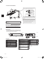 4
4
-
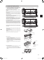 5
5
-
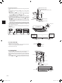 6
6
-
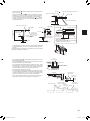 7
7
-
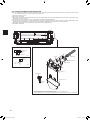 8
8
-
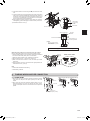 9
9
-
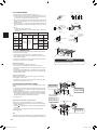 10
10
-
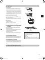 11
11
-
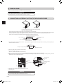 12
12
-
 13
13
-
 14
14
-
 15
15
-
 16
16
-
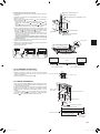 17
17
-
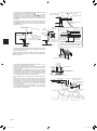 18
18
-
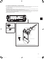 19
19
-
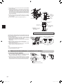 20
20
-
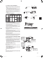 21
21
-
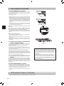 22
22
-
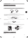 23
23
-
 24
24
-
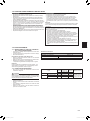 25
25
-
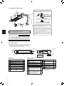 26
26
-
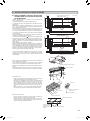 27
27
-
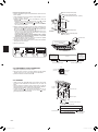 28
28
-
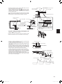 29
29
-
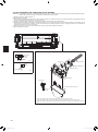 30
30
-
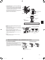 31
31
-
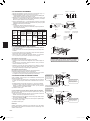 32
32
-
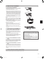 33
33
-
 34
34
-
 35
35
-
 36
36


Mitsubishi Electronics USA MLZ-KP09NA Le manuel du propriétaire
- Catégorie
- Climatiseurs split-system
- Taper
- Le manuel du propriétaire
- Ce manuel convient également à
dans d''autres langues
Documents connexes

Autres documents
-
Mitsubishi Electric KOMPAKT MXZ-2D40VA Guide d'installation
-
Mitsubishi MSZ-HJ35VA Le manuel du propriétaire
-
Mitsubishi Electric MLZ-KP09NA2 Manuel utilisateur
-
-
BAZZ 300L11W Mode d'emploi
-
Mitsubishi MXZ-3B30NA-1 Guide d'installation
-
-
Mitsubishi Electric Mr. SLim SEZ-KD15NA Guide d'installation
-
-