Petsafe HIG11-13655 Guide d'installation
- Catégorie
- S'occuper d'un animal
- Taper
- Guide d'installation

BATTERY 6V
RFA-67
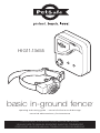
basic in-ground fence
™
operating and training guide / manuel d’utilisation et de dressage
manual de adiestramiento y funcionamiento
HIG11-13655
PLEASE READ THIS ENTIRE GUIDE BEFORE BEGINNING
VEUILLEZ LIRE CE MANUEL EN ENTIER AVANT DE COMMENCER
POR FAVOR, LEA ESTE MANUAL COMPLETO ANTES DE EMPEZAR

2 1-800-732-2677 www.petsafe.net 3

www.petsafe.net 3
Thank you for choosing PetSafe
®
brand. You and your pet deserve a compan-
ionship that includes memorable moments and a shared understanding togeth-
er. Our products and training tools promote a lifestyle of protection, teaching,
and love — essentials that influence memories for a lifetime. If you have any
questions about our products or training your pet, please visit our website at
www.petsafe.net or contact our Customer Care Center at 1-800-732-2677.
To get the most protection out of your warranty, please register your product
within 30 days at www.petsafe.net. By registering and keeping your receipt, you
will enjoy the product’s full warranty and should you ever need to call the Cus-
tomer Care Center, we will be able to help you faster. Most importantly, we will
never give or sell your valuable information to anyone. Complete warranty infor-
mation is available online at www.petsafe.net.

4 1-800-732-2677 www.petsafe.net 5
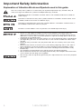
Important Safety Information
Explanation of Attention Words and Symbols used in this guide
This is the safety alert symbol. It is used to alert you to potential personal injury hazards. Obey all
safety messages that follow this symbol to avoid possible injury or death.
WARNING indicates a hazardous situation which, if not avoided, could result in death or
serious injury.
CAUTION, used with the safety alert symbol, indicates a hazardous situation which, if not
avoided, could result in minor or moderate injury.
CAUTION, used without the safety alert symbol, indicates a hazardous situation which, if
not avoided, could result in harm to your pet.
NOTICE is used to address safe use practices not related to personal injury.
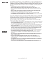
• Not for use with aggressive dogs. Do not use this product if your dog is prone to
aggressive behavior. Aggressive dogs can cause severe injury or death to their owners
and others. If you are not sure that this product is right for your dog, please talk to your
veterinarian or a certified trainer.
• Underground cables can carry high voltage. Have all underground cables marked before
you dig to bury your wire. In most areas this is a free service. Avoid these cables when
you dig.
• Follow all safety instructions for your power tools. Be sure to always wear your safety
goggles.
• Do not install, connect, or remove your system during a lightning storm. If the storm is
close enough for you to hear thunder, it is close enough to create hazardous surges.
• Risk of electric shock. Use the Fence Transmitter and Surge Protector indoors in dry
location only.
• Turn off power to outlet before you install or remove your Surge Protector.
• Risk of electrical shock or fire. Use Surge Protector only with a duplex outlet with center
screw. Attach unit with long screw supplied.
• Risk of injury. Wire on top of the ground may be a trip hazard; Use care in how you place
your wires.

www.petsafe.net 5
This PetSafe
®
In-Ground Fence
™
is not a solid barrier. This system is designed to act as a
deterrent to remind pets by Static Correction to remain in the boundary established. It is
important that you reinforce training with your pet on a regular basis. Proper fit of the collar
is important. A collar worn for too long or made too tight on the pet’s neck may cause skin
damage. Ranging from redness to pressure ulcers; this condition is commonly known as
bed sores.
• Avoid leaving the collar on the dog for more than 12 hours per day.
• When possible reposition the collar on the pet’s neck every 1 to 2 hours.
• Check the fit to prevent excessive pressure; follow the instructions in this manual.
• Never connect a lead to the electronic collar; it will cause excessive pressure on the
contacts.
• When using a separate collar for a lead, don’t put pressure on the electronic collar.
• Wash the dog’s neck area and the contacts of the collar weekly with a damp cloth.
• Examine the contact area daily for signs of a rash or a sore.
• If a rash or sore is found, discontinue use of the collar until the skin has healed.
• If the condition persists beyond 48 hours, see your veterinarian.
• For additional information on bed sores and pressure necrosis, please visit our website.
These steps will help keep your pet safe and comfortable. Millions of pets are comfortable
while they wear stainless steel contacts. Some pets are sensitive to contact pressure. You
may find after some time that your pet is very tolerant of the collar. If so, you may relax
some of these precautions. It is important to continue daily checks of the contact area. If
redness or sores are found, discontinue use until the skin has fully healed.
You may need to trim the hair in the area of the Contact Points. Never shave the dog’s
neck; this may lead to a rash or infection.
• The Receiver Collar should not be on your dog when the system is tested. Your pet may
receive an unintended correction.
• The Boundary Width of the system must be tested whenever an adjustment is made to
the containment field to prevent unintended corrections to your pet.
• If you use a collar and leash for training, be sure the extra collar does not put pressure
on the contact points.
• Always remove your dog’s Receiver Collar before performing any Transmitter testing.
• If possible, DO NOT use an AC circuit protected with a Ground Fault Circuit Interrupter
(GFCI) or Residual Current Device (RCD). In rare cases, nearby lightning strikes may
cause the GFCI or RCD to trip. Without power your dog may be vulnerable to escape.
You will have to reset the GFCI or RCD to restore power to the system.
• Do not install the Surge Protector if there is not at least 30 feet (10 meters) or more of
wire between the electrical outlet and electrical service panel.
• Plug the Surge Protector into a grounded (3-prong) outlet that is within 5 feet of the
Fence Transmitter. ALWAYS use a grounded (3-prong) outlet to ensure maximum
protection.
• Do not remove the ground prong from the Surge Protector plug. Do not use a 3-prong
plug to 2-prong outlet converter. Doing so will make the Surge Protector ineffective
against surges or spikes.
• Use care when mowing or trimming your grass not to cut the loop wire.
• Verify that the boundary loop and Transmitter wires connect to the proper Surge
Protector terminals. Reversed connections will result in an increased risk of surge
related damage.
• For added protection, when unused for long periods of time or prior to thunderstorms,
unplug from the wall outlet and disconnect the loop boundary wires. This will prevent
damage to the transmitter due to surges.
• To prevent an unintended correction, after the Boundary Flags have been placed, be
sure to set the static correction on the receiver collar back to level 1 tone only.

6 1-800-732-2677 www.petsafe.net 7
Table of Contents
Components ............................................................................................................................................... 7
Other Items You May Need ........................................................................................................................ 7
How the System Works ............................................................................................................................... 8
Key Definitions ............................................................................................................................................ 8
Lay Out the System..................................................................................................................................... 9
Basic Planning Tips ................................................................................................................................. 9
Operating Guide
Sample Layouts ......................................................................................................................................... 10
Double Loop ......................................................................................................................................... 10
Position the Boundary Wire ...................................................................................................................... 11
To Twist the Boundary Wire .................................................................................................................. 12
To Splice or Repair the Boundary Wire ................................................................................................ 12
Additional Boundary Wire .................................................................................................................... 12
C
onnect the Wires to the Surge Protector and Fence Transmitter (USA and Canada) ..................................13
Surge Protection ................................................................................................................................... 13
Install the Surge Protector & Connect the Wires (4A) ......................................................................... 13
Transmitter Set-up (Australia and New Zealand) ................................................................................. 14
Prepare the Receiver Collar ...................................................................................................................... 15
To Insert and Remove the Receiver Collar Battery .............................................................................. 15
To Set the Static Correction Level ........................................................................................................ 15
Anti-Linger Prevention ......................................................................................................................... 16
Run Through Prevention ....................................................................................................................... 16
Over Correction Protection .................................................................................................................. 16
Function and Response Table .............................................................................................................. 16
Set the Boundary Width and Test the Receiver Collar ............................................................................... 16
Install the Boundary Wire ......................................................................................................................... 18
To Bury the Boundary Wire .................................................................................................................. 18
To Attach the Boundary Wire to an Existing Fence ............................................................................. 18
To Cross Hard Surfaces (driveways, sidewalks, etc.) ............................................................................ 19
Place the Boundary Flags ......................................................................................................................... 19
Fit the Receiver Collar .............................................................................................................................. 20
Training Guide
Be Patient With Your Pet .......................................................................................................................... 22
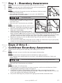
Day 1 - Boundary Awareness .................................................................................................................... 23
Days 2 thru 4 - Continue Boundary Awareness ....................................................................................... 23
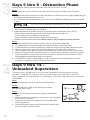
Days 5 thru 8 - Distraction Phase ................................................................................................................ 24
Days 9 thru 14 - Unleashed Supervision ..................................................................................................... 24
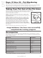
Days 15 thru 30 - Pet Monitoring ............................................................................................................... 25
Taking Your Pet Out of the Pet Area ........................................................................................................ 25
Accessories ............................................................................................................................................... 25
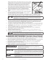
Troubleshooting
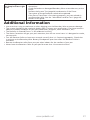
Additional Information .............................................................................................................................. 27
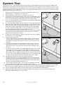
System Test ............................................................................................................................................... 28
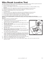
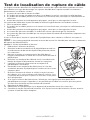
Wire Break Location Test .......................................................................................................................... 29
Terms of Use and Limitation of Liability ................................................................................................... 30
Compliance ............................................................................................................................................... 31
Australia ................................................................................................................................................ 31
Customer Care International .................................................................................................................... 31
Perchlorate Battery ................................................................................................................................... 31
Warranty .................................................................................................................................................... 32
Claims Procedure: ................................................................................................................................. 32
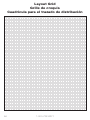
Layout Grid ............................................................................................................................................... 94
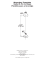
Mounting Template .................................................................................................................................. 96

www.petsafe.net 7
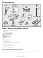
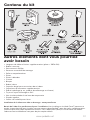
Components
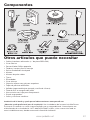
Other Items You May Need
• Additional wire and flags (Part #PRFA-500)
• Tape measure
• Small Phillips screwdriver
• Drill & mounting hardware
• Shovel or lawn edger
• Pliers
• Wire stripping pliers
• Scissors
• Lighter
• Electrical tape
• Gel-filled Capsules
• Additional wire nuts
• Waterproofing compound (e.g. silicone caulk)
• PVC pipe or water hose
• Circular saw with masonry blade
• Staple gun
• Non-metallic collar and leash
Fence installation and training help: www.petsafe.net
Want professional installation help? Invisible Fence
®
Brand installers will come to your home and
install your new PetSafe
®
System for an additional cost. Contact your local dealer at 1-877-866-DOGS
(3647) or visit our website at www.invisiblefence.com for more information.

8 1-800-732-2677 www.petsafe.net 9
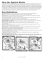
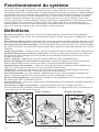
How the System Works
The PetSafe
®
Basic In-Ground Fence
™
has been proven safe, comfortable, and effective for pets over
8 pounds. The system works by producing a radio signal from the Fence Transmitter through up to
2000 feet of Boundary Wire. The Boundary Wire is buried or attached to a fixed object to enclose the
Pet Area. You temporarily define this Pet Area with Boundary Flags for a visual aid in training your pet.
Your pet wears a Receiver Collar with Contact Points that touch his neck, and once trained, is allowed
to roam freely in the Pet Area. When your pet reaches the Warning Zone, the Receiver Collar gives a
warning beep. If your pet continues into the Static Correction Zone, a safe Static Correction will be
delivered through the Contact Points to get his attention until he returns to the Pet Area.
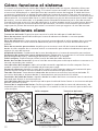
Key Definitions
Fence Transmitter: The device that transmits the radio signal through the Boundary Wire.
Pet Area: The area within the Warning Zone where your pet can roam freely.
Warning Zone: The outer edge of the Pet Area where your pet’s Receiver Collar begins to beep,
warning him not to go into the Static Correction Zone.
Static Correction Zone: The zone beyond the Warning Zone where your pet’s Receiver Collar will
emit a Static Correction, signaling him to return to the Pet Area.
Boundary Width: The combination of the Warning Zone and the Static Correction Zone.
Surge Protector: Installed with the Fence Transmitter to protect it from lightning strikes and power
surges (USA and Canada only).
Receiver Collar: The device that receives the radio signal from the Boundary Wire.
Correction Level Button: Adjusts the level of Static Correction your pet receives in the Static
Correction Zone.
Receiver Indicator Light: Indicates the level of correction at which the Receiver Collar is set. This
light also serves as the low battery indicator.
Contact Points: The contacts through which the Receiver Collar delivers the safe Static Correction
when your pet moves into the Static Correction Zone.
Power Jack: The Jack where the Power Adapter plugs into the Fence Transmitter. The Fence
Transmitter is powered by a standard 120-volt outlet.
Boundary Wire Terminals: The terminals where the Boundary Wires connect to the Fence Transmitter
in order to complete a continuous loop.
Loop Indicator Light: The light that indicates that the Boundary Wire makes a complete loop,
enabling the signal to be transmitted.
Boundary Width Control: The knob that adjusts the width of the Warning and Static Correction
Zones. Note: Adjusting the knob does not change the level of Static Correction on the Receiver Collar.
Receiver Collar Fence Transmitter

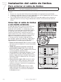
www.petsafe.net 9
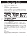
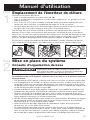
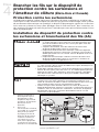
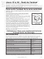
Locate the Fence Transmitter
Place the Fence Transmitter:
• In a dry, well ventilated, protected area (1A, 1B).
• In an area where temperatures do not fall below freezing (e.g., garage, basement,
shed, closet).
• Secured to a stationary surface using appropriate mounting hardware (not included). A
mounting template is included in the back of this guide.
• At least 3 feet from large metal objects or appliances as these items may interfere with
the signal consistency (1C).
Once you have mounted the Fence Transmitter, the Boundary Wire must exit the building.
This can be accomplished via a window or through a hole drilled through the wall. Ensure
the drill path is clear of any utilities. Make sure the Boundary Wire is not cut off or pinched
by a window, door, or garage door, as this can damage it over time.
To prevent fires and electrical hazards, install the Fence Transmitter in buildings that are in
accordance with state and local electrical codes.
1A
1B 1C
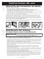
Lay Out the System
Basic Planning Tips
Underground cables can carry high voltage. Have all underground cables marked
before you dig to bury your wire. In most areas this is a free service. Avoid these
cables when you dig.
For information regarding how these underground wires can affect your system’s
operation, see Step 3 Position the Boundary Wire.
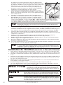
• The Boundary Wire MUST start at the Fence Transmitter and make a continuous loop
back (2A).
• Twisting the Boundary Wire cancels the signal and allows your pet to cross over that area
without correction. Plastic or metal piping will not cancel the signal. Twist the Boundary
Wire 10 to 12 times per foot to cancel the signal (2A).
• Design a layout that is suitable for your yard. Sample layouts are provided in this section,
and a grid for designing your layout is provided in the back of this guide.
• Always use gradual turns at the corners with a minimum of 3 foot radius to produce a
more consistent boundary (2B). Do not use sharp turns, as this will cause gaps in your
boundary.
• To properly contain your pet, we recommend setting a Boundary Width for the Warning
and Static Correction Zones to approximately 12-20 feet (6 to 10 feet on each side of the
wire).
• Avoid making passageways too narrow for your pet to move about freely (e.g., along the
sides of a house).
• The Receiver Collar can be activated inside the house if the Boundary Wire runs along
the outside wall of the house. If this occurs, remove your pet’s Receiver Collar before
bringing him inside, decrease the range using the Boundary Width Control knob or
consider an alternative layout.
Step
1
Step
2
Operating Guide

10 1-800-732-2677 www.petsafe.net 11
2A 2B
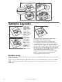
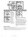
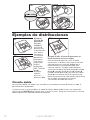
Sample Layouts
2C
2D
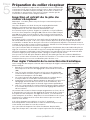
Sample 1:
Perimeter
Loop (Single
Loop) The
Perimeter
Loop is the
most common
layout. This
will allow
your pet to
freely and
safely roam
your entire
property
(2C). It can
also protect
gardens,
pools and
landscaping
(2D).
2E
Sample 2 (2E): Perimeter Loop Using
Existing Fence (Single Loop)
This layout allows you to include your
existing fence as part of your layout and
keep your pet from jumping out or digging
under your existing fence. It reduces the
amount of wire which will need to be buried.
From the Fence Transmitter, run the wire to
A, A to B, B to C, C to D, D to E, E to A, twist
the wires from A back to the Fence
Transmitter. See the “Install the Boundary
Wire” section for more information on
attaching the wire to a fence.
Double Loop
A Double Loop must be used when you are not establishing the Boundary Zone on all sides
of your property.
When using a Double Loop, the Boundary Wire must be separated by a minimum of FIVE
FEET to avoid canceling the signal. Remember that a Double Loop will require twice as
much wire.

www.petsafe.net 11
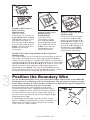
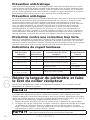
2F
Sample 3 (2F): Front or
Back Yard Only
(Double Loop)
From the Fence
Transmitter, run the wire to
A, A to B, B to C, C to D, D
to E, E to F, make a U-turn
and follow your path all
the way back to A, keeping
the wire separated at least
5 feet. Twist the wire from
A back to the Fence
Transmitter.
2G
Sample 4 (2G): Front
Boundary Only
(Double Loop)
From the Fence
Transmitter, run the
wire to A, A to B, B
back to A keeping the
wire separated at least
5 feet. Twist the wire
from A back to the
Fence Transmitter.
2H
Sample 5 (2H): Lake Access
(Double Loop)
From the Fence Transmitter,
run the wire to A, A to B,
make a U-turn and go to C,
C to D, D to E, make a U-turn
and follow your path all the
way back to A keeping wire
separated at least 5 feet.
Twist the wire from A back
to the Fence Transmitter.
Sample 6 (2J): Wire Loop Attached to Existing Fence
(Double Loop)
This layout allows you to include your existing fence as part of
your layout and keep your pet from jumping out or digging
under your existing fence. It reduces the amount of wire which
will need to be buried. Run the wire from the Fence Transmitter
to A, A to B, B to C, C to D, D to E, E to F, make a U-turn and
follow your path all the way back to A, keeping the wire
separated at least 5 feet. Twist the wire from A back to the
Fence Transmitter. See the “Install the Boundary Wire” section
for more information on attaching the wire to a fence.
2J
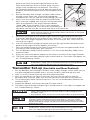
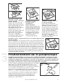
Position the Boundary Wire
Lay out the Boundary Wire using your planned boundary and test the system BEFORE
burying the wire or attaching it to an existing fence. This will make any layout changes
easier. Work carefully. A nick in the wire insulation can diminish the signal strength and
create a weak area where your pet can escape.
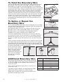
Running the Boundary Wire parallel to and within
10 feet of electrical wires, neighboring containment
systems, telephone wires, television or antenna cables,
or satellite dishes may cause an inconsistent signal. If
you must cross any of these, do so at 90-degree angles
(perpendicularly) (3A).
If separating your Boundary Wire by at least 10 feet
from a neighboring containment system’s wire does not
reduce the inconsistent signal, contact the Customer
Care Center at 1-800-732-2677.
3A
Step
3

12 1-800-732-2677 www.petsafe.net 13
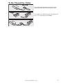
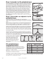
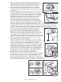
To Twist the Boundary Wire
Twisting the Boundary Wire cancels the signal and allows your
pet to cross over that area safely (3B). The signal cannot be
canceled by running the wire through plastic or metal piping.
Using shielded cable in place of the Boundary Wire will also not
cancel the signal. Refer to figure (3C) for the correct method of
twisting the wire. You can twist your own wire by cutting two
equal lengths of Boundary Wire supplied and twisting them
together. Anchor one end of the wires to something secure and
insert the other end in a power drill. Pull the wire taut. The drill
enables you to twist the wire quickly. Twist the Boundary Wire
10 to 12 times per foot to cancel the signal. Once you have
completed your boundary layout, insert the twisted wire into
the transmitter.
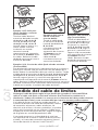
To Splice or Repair the
Boundary Wire
If you need additional Boundary Wire to expand your wire loop,
you will need to splice the wires together. Note the locations of
all splices for future reference.
3C
3B
Strip approximately 3/8 inch of insulation off the ends of the
Boundary Wires to be spliced (3D). Make sure the copper
Boundary Wire is not corroded. If the Boundary Wire is
corroded, cut it back to expose clean copper wire.
Insert the stripped ends into the wire nut and twist the wire
nut around the wires. Ensure that there is no copper exposed
beyond the end of the wire nut. Tie a knot 3 to 4 inches from
the wire nut (3E). Ensure that the wire nut is secure on the wire
splice.
Once you have securely spliced the wires together, open the lid
of the gel-filled splice capsule and insert the wire nut as deeply
as possible into the waterproof gel inside the capsule (3F). Snap
the lid of the capsule shut (3G). For proper system performance,
the splice connection must be waterproof.
3D
If your splice pulls loose,
the entire system will fail.
Make sure your splice is
secure. Additional gel-
filled splice capsules and
wire nuts are available
through the Customer
Care Center.
3E
3F
3G
Additional Boundary Wire
Extra direct burial Boundary Wire can be purchased
in 500 foot spools at the store where you purchased
the kit or through the Customer Care Center at
1-800-732-2677.
Note: When adding Boundary Wire, it must act as a
continuous loop.
The table at right indicates the approximate length
of Boundary Wire needed for a square Single
Loop layout. Length will vary due to the amount of
twisted wire and layout used.
Acres Feet of Wire Needed
1/4 415
1/3 480
1/2 590
1 835
2 1180
5 1870

www.petsafe.net 13
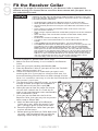
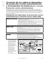
C
onnect the Wires to the Surge
Protector and Fence Transmitter
(USA and Canada)
Surge Protection
Lightning strikes that occur even several miles away from your installation can create power
surges or spikes which may damage your unprotected electronic pet containment system.
The Surge Protector included with this system is designed to protect your In-Ground
Fence
™
from surges or spikes that can reach it via your AC power connection and/or your
buried Boundary Wire.
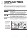
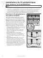
Install the Surge Protector &
Connect the Wires (4A)
• Do not install, connect, or remove your system during a lightning storm.
If the storm is close enough for you to hear thunder, it is close enough to
create hazardous surges.
• Turn off power to outlet before you install or remove your Surge Protector.
• Risk of electrical shock or fire. Use Surge Protector only with a duplex outlet
with center screw. Attach unit with long screw supplied.
• Risk of electric shock. Use the Fence Transmitter and Surge Protector
indoors in dry location only.
• Do not install the Surge Protector if there is not at least 30 feet (10 meters)
or more of wire between the electrical outlet and electrical service panel.
• If possible, DO NOT use an AC circuit protected with a GFCI (ground fault
circuit interrupter). In rare cases, nearby lightning strikes may cause the
GFCI to trip. Without power your dog may be vulnerable to escape. You will
have to reset the GFCI to restore power to the system.
• Plug the Surge Protector into a grounded (3-prong) outlet that is within 5
feet of the Fence Transmitter. ALWAYS use a grounded (3-prong) outlet to
ensure maximum protection.
• Do not remove the ground prong from the Surge Protector plug. Do not use
a 3-prong plug to 2-prong outlet converter. Doing so will make the Surge
Protector ineffective against surges or spikes.
1. Turn the power OFF
to the outlet that the
Surge Protector and
Fence Transmitter will
be plugged into.
2. We recommend
that, if possible, use
the outlet center
screw that holds the
cover plate in place
to secure the Surge
Protector to the
outlet. To do this, tape
the top of the cover
plate to the wall, then
remove the cover
4A
Step
4

14 1-800-732-2677 www.petsafe.net 15
plate center screw. Plug the Surge Protector into the
lower outlet and then secure the cover plate using the
longer screw included with the protector. The screw is
for mechanical attachment only and does not ground the
protector. Remove the tape and turn ON the power to the
outlet.
3. Run the Boundary Wire through a window, under a door,
through a crawl space vent, or any other appropriate
available access. You can also drill a hole through your wall.
4. Strip
3
⁄
8
inch of insulation from the ends of the Boundary
Wire. Insert the stripped ends into the 2 left red connector
holes on the bottom of the Surge Protector labeled
“Loop” (4B). There should be 1 wire in each connector
hole. Press the plastic tab, insert the wires and release the
4B
tab. Make sure the wires do not touch each other at the terminals.
Verify that the boundary loop and transmitter wires connect to the proper
Surge Protector terminals. Reversed connections will result in an increased
risk of surge related damage.
5. Determine the length of wire needed to pass from the Surge Protector to the Fence
Transmitter. Measure and cut 2 lengths of wire, then strip
3
⁄
8
inch of insulation at both
ends. Twist the 2 lengths together, with at least 10-12 twists per foot, so the wires will
not send out a signal.
6. Insert the ends of the twisted transmitter wires into the right 2 black connectors at the
bottom of the Surge Protector labeled “Transmitter”.
7. Press the red plastic tabs on the Fence Transmitter and insert the opposite ends of the
twisted wire into the Boundary Wire Terminals.
8. Turn the Boundary Width Control knob to 10. This will set the Boundary Width at the
maximum width.
9. Plug in the transmitter power adapter to the outlet on the front of the Surge Protector.
10. The Power Light and Loop Indicator Lights should come on. If this does not happen, see
the “Troubleshooting” section.
For added protection, when unused for long periods of time or prior to
thunderstorms, unplug from the wall outlet and disconnect the loop boundary
wires. This will prevent damage to the transmitter due to surges.
Transmitter Set-up (Australia and New Zealand)
1. Run the Boundary Wire through a window, under a door, through a crawl space vent, or
any other appropriate available access. you can also drill a hole through your wall.
2. Strip
3
⁄
8
inch of insulation from the ends of the Boundary Wire.
3. Press the red tabs on the Fence Transmitter and insert the twisted wire into the
Boundary Wire Terminals. Make sure wires do not touch each other at the terminals.
4. Turn the Boundary Width Control Knob to 10. This will set the Boundary Width at the
maximum width.
5. Plug Power Adapter into Power Jack and AC Power Outlet.
6. The Power Light and Loop Indicator Lights should come on. If this does not happen see
the “Troubleshooting” section.
• Do not install, connect, or remove your system during a lightning storm. If the
storm is close enough for you to hear thunder, it is close enough to create
hazardous surges.
• Risk of electric shock. Use the Fence Transmitter indoors in dry location only.
If possible, DO NOT use an AC circuit protected with a Ground Fault Circuit
Interrupter (GFCI) or Residual Current Device (RCD). In rare cases, nearby
lightning strikes may cause the GFCI or RCD to trip. Without power your dog
may be vulnerable to escape. You will have to reset the GFCI or RCD to restore
power to the system.
For added protection, when unused for long periods of time or prior to
thunderstorms, unplug from the wall outlet and disconnect the loop boundary
wires. This will prevent damage to the transmitter due to surges.

www.petsafe.net 15
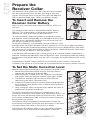
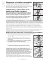
Prepare the
Receiver Collar
Your Receiver Collar comes with short Contact Points installed.
Use the long Contact Points for pets with long or thick hair.
Tighten the Contact Points using the Test Light Tool (5A) one-
half turn beyond finger tight. Check the tightness weekly.
To Insert and Remove the
Receiver Collar Battery
Note: Do not install the battery while the Receiver Collar is on
your pet.
This Receiver Collar utilizes a replaceable PetSafe
®
battery
(RFA-67). This unique battery is designed to make battery
replacement easier and increase water protection.
To insert the battery, align the symbols on the battery (arrow)
and Receiver Collar (triangle) (5B). Use the edge of the Test Light
Tool (5A) to turn the battery clockwise until the arrow lines up
with the lock symbol on the housing.
5A
5B
5C
To remove the battery, turn the battery counter-clockwise using
the edge of the Test Light Tool (5C). DO NOT attempt to cut into or pry open the battery.
Be sure to discard the used battery properly. Battery life will vary depending on how often
your pet tests the system and receives a Static Correction. Check the Receiver Collar every
month to ensure the battery is working properly.
If the Receiver LED Indicator Light is flashing every 4 to 5 seconds, battery replacement is
required. Remove the old battery from the Receiver Collar. Discharge all power by holding
the correction level button down until the LED is no longer illuminated. Replace with a new
battery.
A replacement PetSafe
®
battery (RFA-67) can be found at many retailers. Contact the
Customer Care Center or visit our web site at www.petsafe.net to locate a retailer near you.
To Set the Static Correction Level
Read all steps before attempting to set the Static Correction Level.
1. Remove the clear plastic cover with the Test Light Tool to
expose the Correction Level Button (5D).
2. With the battery installed, press the Correction Level Button
and release when the Receiver Indicator Light lights up (5E).
3. The Receiver Indicator Light will emit a series of flashes
representing the Static Correction Level.
4. Increase the Static Correction Level by pressing and releasing
the Correction Level Button within 5 seconds of the previous
series of flashes.
5. After setting the Static Correction Level, replace the cover to
protect the Correction Level Button.
The Static Correction levels increase in strength from 1 to 5.
Pushing the Correction Level Button while the Receiver Collar is on
level 5 will cause the Receiver Collar to revert to Level 1. Refer to
the Function and Response Table to choose the Static Correction
level that best fits your pet.
The Receiver Collar is equipped to automatically increase the
level of Static Correction the longer your pet remains in the Static
Correction Zone if the collar is set at level 2 or above.
The Receiver LED Indicator Light acts as a low battery indicator,
flashing every 4 to 5 seconds when replacement is required.
5D
5E
Step
5

16 1-800-732-2677 www.petsafe.net 17
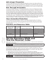
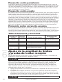
Anti-Linger Prevention
The Anti-Linger Prevention feature keeps your dog from staying in the Warning Zone for
long periods of time and draining the Receiver Collar battery. Your dog will hear a warning
tone when he reaches the Warning Zone. If your dog does not return to the Pet Area after
two seconds, he will receive a continuous Static Correction until he returns to the Pet Area.
Run Through Prevention
This system includes a unique “run-through” prevention so that your dog cannot escape
the Pet Area without receiving an increased level of Static Correction. The Receiver Collar
automatically increases the Static Correction when your dog continues more than 20% of
the way through the pet fencing Boundary Width. For example, if the signal is detected 10
feet from the wire and your dog enters the Static Correction Zone, this feature is activated
when he is approximately 8 feet from the Boundary Wire. Your dog will then receive a Static
Correction that is at an increased level corresponding to the Static Correction level setting
on the Receiver Collar. The Receiver Collar is equipped to automatically increase the level of
Static Correction the longer your pet remains in the Static Correction Zone if the collar is set
at level 2 or above. The Run Through Prevention sound is an intermittent tone.
Over Correction Protection
In the unlikely event that your pet “freezes” in the Static Correction Zone, this feature
limits the static correction duration to a maximum of 30 seconds. While the system locks
out further static correction, the warning tone will continue until the pet leaves the Static
Correction Zone.
Function and Response Table
Indicator Light
Response
Static
Correction
Level
Receiver Collar Function Temperament of Pet
1 Flash 1 No Static Correction, Tone Only Initial Training Mode
2 Flashes 2 Low Static Correction Timid
3 Flashes 3 Medium Static Correction Timid or Average
4 Flashes 4 Medium High Static Correction Average or High Energy
5 Flashes 5 High Static Correction High Energy
Flashes once every
4 to 5 seconds
Indicates Low Battery
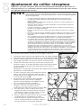
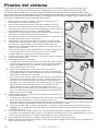
Set the Boundary Width and
Test the Receiver Collar
With the Boundary Wire in place and properly connected, it is time to set the containment
field and test the system.
The Receiver Collar should NOT be on your dog when the system is tested.
Note: The Receiver Collar is waterproof, which can make the tone hard to hear.
The flashing Test Light when held to the Contact Points indicates the Receiver Collar is
delivering Static Correction. To best utilize the automatic Run-Through Prevention feature,
the containment Boundary Width should extend at least 6 to 10 feet on each side of the
Boundary Wire (total Boundary Width of 12 to 20 feet).
1. Apply Power to the Fence Transmitter with the supplied Power Adapter.
2. The width of the containment field is adjusted using the transmitter’s Boundary Width
Control knob. Turn the knob counter clockwise until the Loop Indicator Light is no
longer lit. Turn the knob clockwise and increase by 2 numbers. The light should turn ON.
The Receiver Collar should not be on your dog when the system is tested.
Your pet may receive an unintended correction.
Step
6

www.petsafe.net 17
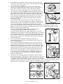
3. Place battery in Receiver Collar. To identify the Warning
and Static Correction Zones make sure the Receiver Collar
is set at level 5 (see Step 5).
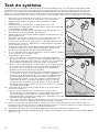
4. Test the Boundary Width of the system by selecting a
section of straight Boundary Wire that is at least 50 feet
long. Start inside the center of the containment field.
5. Place the Test Light Tool Contacts on the Contact Points
on the Receiver Collar (6A,6B). Hold the Receiver Collar at
your dog’s neck height with the Contact Points pointing up
(6C) and the Correction Level Button facing the Boundary
Wire. Slowly walk toward the Boundary Wire until you hear
the warning tone (6E). When you hear the warning tone,
you have identified the Boundary Width distance (Static
Correction Zone).
Two seconds after the warning tone, the test light will
begin to flash. This flashing light can aid you in identifying
the Boundary Width should you have difficulty hearing the
tone. To avoid having the Receiver Collar go into Over
6A
6B
Correction Protection mode, walk back into the Pet Area until the toning stops.
If the
Receiver Collar does not tone at the desired range, adjust the Boundary Width Control
knob to obtain the desired range.
Turning the Boundary Width Control knob clockwise
increases the Boundary Width while turning it
counterclockwise decreases
it (6E). Repeat this activity as
needed until the Receiver Collar tones between 6 to 10 feet
from the Boundary Wire. If using a Double Loop layout, you
may need to increase the separation of the Boundary Wire
and/or increase the size of the Boundary Width to achieve
the desired range.
6. Test in a number of different locations around the
containment area until you are satisfied that the system is
functioning properly.
7. Next, walk all around the Pet Area to ensure there are no
areas where the Receiver Collar may activate from signals
coupled onto buried wires or cables. Test the collar in and
around the inside of the house as well. As mentioned, cable
and wires from cable TV, electrical or telephone lines may
conduct pet fencing signals inside and outside the house
that can activate the dog’s collar accidentally. While rare,
if this occurs your Boundary Wire is probably too close to
these outside lines and should be moved or modified as
shown in Figure 3A.
8. To test the run-through prevention feature, walk towards
the Boundary Wire. The Receiver Collar should tone and the
Test Light should flash brighter as you enter the run-through
area (6G). If you are satisfied that your system is functioning
6C
6D
properly, you are ready to start burying the Boundary Wire. If the Receiver Collar did not
tone or the Test Light did not flash, see the “Troubleshooting” section.
6F
6E

18 1-800-732-2677 www.petsafe.net 19
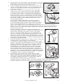
Install the Boundary Wire
To Bury the Boundary Wire
Before you begin installing the Boundary Wire, unplug the Fence Transmitter
power adapter from the outlet.
Burying the Boundary Wire is recommended to protect it and prevent disabling the system.
1. Cut a trench 1-3 inches deep along your planned boundary.
2. Place the Boundary Wire into the trench maintaining some slack to allow it to expand
and contract with temperature variations.
3. Use a blunt tool such as a wooden paint stick to push the Boundary Wire into the trench.
Be careful not to damage the Boundary Wire.
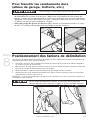
To Attach the Boundary
Wire to an Existing Fence
The Boundary Wire of the PetSafe
®
Basic In-
Ground Fence
™
can be attached to a chain link
fence, split rail fence, or a wooden privacy fence.
The Boundary Wire can be attached as high as
needed. However, make sure the Boundary Width
is set at a high enough range for the pet to receive
the signal. If using a Double Loop with an existing
fence at least five feet tall, run the Boundary Wire
on top of the fence and return it on the bottom of
the fence to get the three to five foot separation
needed.
• Chain Link Fence (7A): Weave Boundary Wire
through the links or use plastic quick ties.
• Wooden Split Rail or Privacy Fence (7A):
Use staples to attach Boundary Wire. Avoid
puncturing the insulation of the Boundary Wire.
• Double Loop with an Existing Fence: Run the
Boundary Wire on top of the fence and return it
on the bottom of the fence to get the three to
five foot separation needed.
• Gate (Single Loop) (7B): Bury the Boundary Wire
in the ground across the gate opening. Note:
The signal is still active across the gate. Your pet
cannot pass through an open gate.
• Gate (Double Loop) (7B): Bury both Boundary
Wires across the gate opening while keeping
them at least five feet apart.
7A
7B
Step
7

www.petsafe.net 19
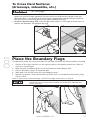
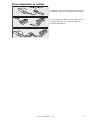
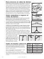
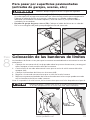
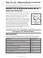
To Cross Hard Surfaces
(driveways, sidewalks, etc.)
• Follow all safety instructions for your power tools. Be sure to always wear
your safety goggles.
• Concrete Driveway or Sidewalk (7C): Place the Boundary Wire in a convenient
expansion joint or create a groove using a circular saw and masonry blade. Place the
Boundary Wire in the groove and cover with an appropriate waterproofing compound.
For best results, brush away dirt or other debris before patching.
• Gravel or Dirt Driveway (7D): Place the Boundary Wire in a PVC pipe or water hose to
protect the Boundary Wire before burying
7C 7D
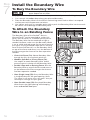
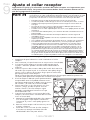
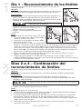
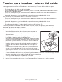
Place the Boundary Flags
The Boundary Flags are visual reminders for your pet of where the Warning Zone is located.
1. Place the Test Light contacts on the contact points and hold the Receiver Collar at
your pet’s neck height.
2. Walk towards the Warning Zone until the Receiver Collar beeps (8A).
3. Place a Boundary Flag in the ground (8B).
4. Walk back into the Pet Area until the beeping stops.
5. Repeat this process around the Warning Zone until it is marked with Boundary Flags
every 10 feet.
Note: If you cannot hear the beep, see the Test Light Instructions in Step 6.
To prevent an unintended correction, after the Boundary Flags have been
placed, be sure to set the static correction on the Receiver Collar back to
level 1 Tone only.
8A 8B
Step
8

20 1-800-732-2677 www.petsafe.net 21
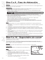
Fit the Receiver Collar
Important: The proper fit and placement of your Receiver Collar is important for
effective training. The Contact Points must have direct contact with your pet’s skin on
the underside of his neck.
Please read and follow the instructions in this manual. Proper fit of the collar is
important. A collar worn for too long or made too tight on the pet’s neck may
cause skin damage. Ranging from redness to pressure ulcers; this condition is
commonly known as bed sores.
• Avoid leaving the collar on the dog for more than 12 hours per day.
• When possible reposition the collar on the pet’s neck every 1 to 2 hours.
• Check the fit to prevent excessive pressure; follow the instructions in this
manual.
• Never connect a lead to the electronic collar; it will cause excessive
pressure on the contacts.
• When using a separate collar for a lead, don’t put pressure on the electronic
collar.
• Wash the dog’s neck area and the contacts of the collar weekly with a
damp cloth.
• Examine the contact area daily for signs of a rash or a sore.
• If a rash or sore is found, discontinue use of the collar until the skin has
healed.
• If the condition persists beyond 48 hours, see your veterinarian.
• For additional information on bed sores and pressure necrosis, please visit
our website. These steps will help keep your pet safe and comfortable.
Millions of pets are comfortable while they wear stainless steel contacts.
Some pets are sensitive to contact pressure. You may find after some time
that your pet is very tolerant of the collar. If so, you may relax some of these
precautions. It is important to continue daily checks of the contact area. If
redness or sores are found, discontinue use until the skin has fully healed.
You may need to trim the hair in the area of the Contact Points. Never
shave the dog’s neck; this may lead to a rash or infection.
To assure a proper fit, please follow these steps:
1. Make sure that the battery is not installed in the Receiver
Collar.
2. Start with your pet standing comfortably (9A).
3. Place the Receiver Collar on your pet so that the “PetSafe”
logo is facing your pet’s chin.
4. Center the Contact Points underneath your pet’s neck,
touching the skin. If your pet has a long or thick coat, use
the enclosed long Contact Points to reach through the hair.
9A
Note: It is sometimes necessary to trim the hair around the Contact Points to make sure
that contact is consistent.
5. The Receiver Collar should fit snugly, yet loose
enough to allow one finger to fit between a
contact point and your pet’s neck (9B).
6. Allow your pet to wear the collar for several
minutes then recheck the fit. Check the fit
again as your pet becomes more comfortable
with the Receiver Collar.
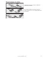
7. Once you are satisfied with the fit of the
Receiver Collar, then you may trim any excess
collar strap as follows (9C):
a. Mark the desired length of the Receiver
Collar with a pen. Allow for growth if your
pet is young or grows a thick winter coat.
b. Remove the Receiver Collar from your pet
and cut off the excess
c. Before placing the Receiver Collar back onto
your pet, seal the edge of the cut collar by
applying a flame along the frayed edge.
9C
9B
Step
9
La page charge ...
La page charge ...
La page charge ...
La page charge ...
La page charge ...
La page charge ...
La page charge ...
La page charge ...
La page charge ...
La page charge ...
La page charge ...
La page charge ...
La page charge ...
La page charge ...
La page charge ...
La page charge ...
La page charge ...
La page charge ...
La page charge ...
La page charge ...
La page charge ...
La page charge ...
La page charge ...
La page charge ...
La page charge ...
La page charge ...
La page charge ...
La page charge ...
La page charge ...
La page charge ...
La page charge ...
La page charge ...
La page charge ...
La page charge ...
La page charge ...
La page charge ...
La page charge ...
La page charge ...
La page charge ...
La page charge ...
La page charge ...
La page charge ...
La page charge ...
La page charge ...
La page charge ...
La page charge ...
La page charge ...
La page charge ...
La page charge ...
La page charge ...
La page charge ...
La page charge ...
La page charge ...
La page charge ...
La page charge ...
La page charge ...
La page charge ...
La page charge ...
La page charge ...
La page charge ...
La page charge ...
La page charge ...
La page charge ...
La page charge ...
La page charge ...
La page charge ...
La page charge ...
La page charge ...
La page charge ...
La page charge ...
La page charge ...
La page charge ...
La page charge ...
La page charge ...
La page charge ...
La page charge ...
-
 1
1
-
 2
2
-
 3
3
-
 4
4
-
 5
5
-
 6
6
-
 7
7
-
 8
8
-
 9
9
-
 10
10
-
 11
11
-
 12
12
-
 13
13
-
 14
14
-
 15
15
-
 16
16
-
 17
17
-
 18
18
-
 19
19
-
 20
20
-
 21
21
-
 22
22
-
 23
23
-
 24
24
-
 25
25
-
 26
26
-
 27
27
-
 28
28
-
 29
29
-
 30
30
-
 31
31
-
 32
32
-
 33
33
-
 34
34
-
 35
35
-
 36
36
-
 37
37
-
 38
38
-
 39
39
-
 40
40
-
 41
41
-
 42
42
-
 43
43
-
 44
44
-
 45
45
-
 46
46
-
 47
47
-
 48
48
-
 49
49
-
 50
50
-
 51
51
-
 52
52
-
 53
53
-
 54
54
-
 55
55
-
 56
56
-
 57
57
-
 58
58
-
 59
59
-
 60
60
-
 61
61
-
 62
62
-
 63
63
-
 64
64
-
 65
65
-
 66
66
-
 67
67
-
 68
68
-
 69
69
-
 70
70
-
 71
71
-
 72
72
-
 73
73
-
 74
74
-
 75
75
-
 76
76
-
 77
77
-
 78
78
-
 79
79
-
 80
80
-
 81
81
-
 82
82
-
 83
83
-
 84
84
-
 85
85
-
 86
86
-
 87
87
-
 88
88
-
 89
89
-
 90
90
-
 91
91
-
 92
92
-
 93
93
-
 94
94
-
 95
95
-
 96
96


Petsafe HIG11-13655 Guide d'installation
- Catégorie
- S'occuper d'un animal
- Taper
- Guide d'installation
dans d''autres langues
Documents connexes
-
Petsafe HIG11-11052 Mode d'emploi
-
-
-
-
-
-
-
-
-
