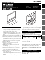
Yamaha YTS-T500 Le manuel du propriétaire
- Catégorie
- Tuners TV d'ordinateur
- Taper
- Le manuel du propriétaire
La page est en cours de chargement...
La page est en cours de chargement...

1 En/Fr
English Français
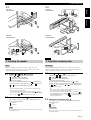
ASSEMBLING/MONTAGE
1-1 1-2
• y indicates a tip for your operation.
• In the MEMO box, note down dimensions and the number (on the mounting
template) measured during assembly.
• Make sure to perform this installation with 2 or more
people.
• Make sure to have a Phillips screwdriver that fits the
screws before assembling.
• In the case you secure parts or the TV with more than 4
screws, tighten all screws temporarily halfway, then
secure them in order of opposing corner.
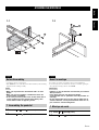
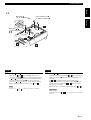
1-1 Attach to with (7 screws).
1-2 Attach with (3 screws).
English
Before Assembling
Notes
1 Assembling the pedestal
•Le symbole y appelle votre attention sur un conseil d’utilisation.
• Lors du montage, notez les dimensions mesurées et le numéro (qui figure
sur le gabarit de montage) dans le cadre MÉMO.
• Veillez à ce que l’installation soit effectuée par au moins
deux personnes.
• Vous devez disposer d’un tournevis Phillips
correspondant aux vis spécifiées avant de procéder au
montage.
• Si vous utilisez plus de 4 vis pour fixer le téléviseur ou
d’autres éléments, serrez provisoirement toutes les vis,
puis serrez-les à fond en diagonale.
1-1 Fixez à avec (7 vis).
1-2 Fixez avec (3 vis).
Français
Avant le montage
Remarques
1 Montage du socle

ASSEMBLING/MONTAGE
2 En/Fr
Blanket, etc.
Couverture, etc.
TV stand
Support TV
2-1 2-2
X
Y
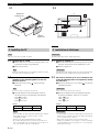
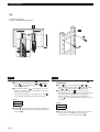
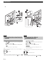
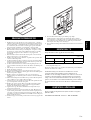
Also refer to the owner’s manual of your TV.
2-1 Remove the TV stand.
1 Place a blanket, etc. on a flat area, and place the TV on it
so that the screen does not get damaged.
2 Remove the TV stand.
Stand removal method may vary, depending on the TV. For details,
refer to the owner’s manual of your TV.
2-2 Measure the distance (X and Y) and the
diameter of the mounting holes on the rear
panel of your TV.
1 Measure the X and Y using or other measuring
instrument.
If screws are on the screw holes, remove them.
2 Check the diameter of the mounting hole of the TV.
Use the following screws depending on the diameter:
5 mm: (4 screws)
6 mm: (4 screws)
8 mm: (4 screws)
MEMO
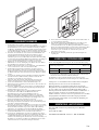
• Before installing, check the depth of the mounting hole of the TV.
If the supplied screws do not fit, use washers or screws
commercially available.
• Prepare screws that can be tightened at least 5 turns.
• Be careful of the length of the screws if the round of the screw
holes sag downwards. Also, do not tighten screws too much as it
may cause distortion of the TV or other damage.
English
2 Installing the TV
Note
Note
Note
XYScrew
cm cm
Notes
Consultez également le mode d’emploi du téléviseur.
2-1 Retirez le support TV.
1 Placez une couverture sur une surface plane, puis posez le
téléviseur dessus afin de ne pas endommager l’écran.
2 Retirez le support TV.
La méthode de retrait du support peut varier en fonction du téléviseur.
Pour plus de détails, consultez le mode d’emploi du téléviseur.
2-2 Mesurez la distance (X et Y) et le diamètre des
trous de montage situés sur le panneau arrière
du téléviseur.
1 Mesurez les distances X et Y à l’aide de ou d’un autre
instrument de mesure.
Si les vis se trouvent dans les trous, retirez-les.
2 Mesurez le diamètre du trou de montage du téléviseur.
En fonction du diamètre, utilisez les vis suivantes :
5mm: (4vis)
6mm: (4vis)
8mm: (4vis)
MÉMO
• Avant l’installation, vérifiez la profondeur du trou de montage du
téléviseur. Si les vis fournies ne rentrent pas, utilisez des rondelles
et des vis vendues dans le commerce.
• Préparez des vis pouvant être serrées d’au moins 5 tours.
• Veillez à ne pas utiliser de vis trop longues, car celles-ci risquent de
se plier. Par ailleurs, ne serrez pas trop les vis, car vous risqueriez
de déformer le téléviseur.
Français
2 Installation du téléviseur
Remarque
Remarque
Remarque
XYVis
cm cm
Remarques

ASSEMBLING/MONTAGE
3 En/Fr
English Français
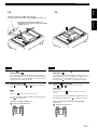
When using
Lors de l’utilisation de
When using /
Lors de l’utilisation de
/
2-3
Screws checked in 2-2-2
Vis définies à l’étape 2-2-2
*
2
*
1
2-3 Attach and .
The holes for and vary depending on the screw
checked in step 2-2-2. Refer to *1 in the illustration above.
If and touch each other when you place them on the
TV (if X checked in step 2-2-1 is 20 cm), reverse the
position of and . Refer to *2 in the illustration above.
Refer to the illustration above, and secure and .
The arrows on and should be toward the top of the TV.
English
Note
2-3 Fixez et .
Le nombre de trous que possèdent et varie selon les vis
définies à l’étape 2-2-2. Reportez-vous à l’illustration *1
ci-dessus.
Si et se touchent lorsque vous les placez sur le
téléviseur, (si la distance X mesurée à l’étape 2-2-1 est de
20 cm), inversez la position de et . Reportez-vous à
l’illustration *2 ci-dessus.
Reportez-vous à l’illustration ci-dessus, puis fixez et .
Les flèches situées sur et doivent être dirigées vers le haut du
téléviseur.
Français
Remarque

ASSEMBLING/MONTAGE
4 En/Fr
2-4
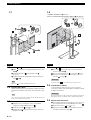
i.e. When using YSP-4100
Par ex., lors de l’utilisation de YSP-4100
2-4 Check the location to attach and the TV.
1 Place over mounting hole A on or so that the
hole on aligns with mounting hole A on or
, as
shown in the illustration.
2 Check which number on is at the bottom of your TV.
Refer to the number shown on the bar that corresponds to
the name of your speaker.
If no number pertaining to your speaker exists, align
with mounting hole B, and check the number again.
MEMO
3 Tighten (2 screws) temporarily around 5 turns into the
holes at the same height as the corresponding number you
checked in 2.
English
Number
2-4 Vérifiez l’emplacement de montage de sur
le téléviseur.
1 Placez sur le trou de montage A de ou de
manière à aligner le trou situé sur au trou de montage
A de ou
, comme indiqué dans l’illustration.
2 Vérifiez quel numéro de est inscrit sur la partie
inférieure du téléviseur. Reportez-vous au numéro indiqué
sur la barre qui correspond au nom du haut-parleur.
Si aucun numéro n’est assigné à votre haut-parleur,
alignez au trou de montage B, puis vérifiez à nouveau
le numéro.
MÉMO
3 Serrez provisoirement (2 vis) d’environ 5 tours dans
les trous situés à la même hauteur que le numéro
correspondant que vous avez noté à l’étape 2.
Français
Numéro

ASSEMBLING/MONTAGE
5 En/Fr
English Français
Only when the X checked in 2-2-1 is 60 cm
Uniquement lorsque la distance X mesurée à l’étape
2-2-1 est de 60 cm
When the X checked in 2-2-1 is other than 60 cm
Lorsque la distance X mesurée à l’étape 2-2-1 n’est pas de 60 cm
2-5 2-6
2-5 Tighten (2 screws) temporarily in advance
to attach TV to .
If you checked which mounting holes to use with A in step
2-4, use mounting hole A, or in the case of B, use B. Refer to
the illustration above, and tighten (2 screws) temporarily
around 5 turns into either A or B.
2-6 Prepare to attach .
Place temporarily over and , and check which hole
to use.
The arrow on should be toward the top of the TV.
If you use mounting hole B in step 2-5, the mounting holes to
attach are shown below.
English
Note
i.e. When X checked in 2-2-1 is 40 cm
: position to tighten the screws
2-5 Serrez provisoirement (2 vis) pour fixer le
téléviseur à .
Si vous avez noté les trous de montage à utiliser avec A à
l’étape 2-4, utilisez le trou de montage A, ou B dans le cas de
B. Reportez-vous à l’illustration ci-dessous, puis vissez
provisoirement (2 vis) d’environ 5 tours dans A ou B.
2-6 Préparez pour le fixer.
Placez sur et , et vérifiez le trou à utiliser.
Les flèches situées sur doivent être dirigées vers le haut du
téléviseur.
Si vous utilisez le trou de montage B à l’étape 2-5, les trous
de montage permettant de fixer sont indiqués ci-dessous.
Français
Remarque
Par ex., lorsque la distance X mesurée à l’étape 2-2-1
est de 40 cm
: position pour serrer les vis

ASSEMBLING/MONTAGE
6 En/Fr
2-7 2-9
i.e. When X checked in 2-2-1 is 40 cm
Par ex., lorsque la distance X mesurée à l’étape 2-2-1 est de 40 cm
2-7 Attach to .
1 Hang on the screws you tightened temporarily in step
2-4-3.
2 Secure the bottom of to the pedestal with
(2 screws).
3 Tighten the temporarily tightened screws on which you
hung in 1.
Make sure is securely attached with 4 screws.
2-8 Connect the cables.
Before mounting the TV to the pedestal, complete the cable
connections. For details, refer to the owner’s manual of your
TV.
Also connect the cable for the speaker to the TV. For the details, refer
to the owner’s manual of your speaker.
2-9 Mount your TV.
1 Hang the TV by inserting the screws you tightened
temporarily in step 2-5 to the holes of .
2 Secure the TV and with (2 screws).
3 Tighten the temporarily tightened screws on which you
hung the TV in 1.
English
Note
Note
2-7 Fixez à .
1 Accrochez aux vis que vous avez provisoirement
serrées à l’étape 2-4-3.
2 Fixez la partie inférieure de au socle avec (2 vis).
3 Serrez provisoirement les vis sur lesquelles vous avez
accroché à l’étape 1.
Assurez-vous que est correctement fixé à l’aide des 4 vis.
2-8 Raccordez les câbles.
Avant d’installer le téléviseur sur le socle, vous devez
raccorder les câbles. Pour plus de détails, consultez le mode
d’emploi du téléviseur.
Raccordez également le câble qui relie le haut-parleur au téléviseur.
Pour plus de détails, consultez le mode d’emploi du haut-parleur.
2-9 Montez votre téléviseur.
1 Accrochez le téléviseur en insérant les vis que vous avez
provisoirement serrées à l’étape 2-5 dans les trous de .
2 Fixez le téléviseur et avec (2 vis).
3 Serrez provisoirement les vis sur lesquelles vous avez
accroché le téléviseur à l’étape 1.
Français
Remarque
Remarque

ASSEMBLING/MONTAGE
7 En/Fr
English Français
YAS-81/71
YSP-4000
YSP-5100/4100
3-1
YAS-81/71
YHT-S1400/S400
YHT-S1400/S400
3-2
YSP-4000
YSP-5100/4100
YAS-81/71
YHT-S1400/S400
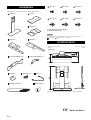
• Before mounting the speaker to the pedestal, complete the cable
connections. For details, refer to the owner’s manual of your speaker.
• Remove the speaker stand when it is attached.
3-1 Attach or with (4 screws).
Choose or depending on the speaker.
: YSP-4000, YSP-5100/4100
: YAS-81/71, YHT-S1400/S400
(As of October, 2009)
In the case of YHT-S1400/S400, attach to the terminal
side of the speaker. Align the holes on and , and stick
to as shown in the illustration above.
y
• You can adjust the height to set the speaker by using the holes
either at the top or at the bottom.
• You can adjust the height of the speaker by setting upside
down, only if you use and your speaker is YHT-S1400/S400. In
this case, attach to the terminal side of the speaker.
3-2 Mount the speaker with .
The number of screws you use varies depending on the
speaker bracket attached.
: 4 screws
: 2 screws
Be careful not to pinch the speaker cables between the speaker and
the speaker bracket.
English
3 Installing the speaker
Notes
Note
• Avant d’installer le haut-parleur sur le socle, vous devez raccorder les
câbles. Pour plus de détails, consultez le mode d’emploi du haut-parleur.
• Retirez le support du haut-parleur si celui-ci est fixé.
3-1 Fixez ou avec (4 vis).
Choisissez ou en fonction du haut-parleur.
: YSP-4000, YSP-5100/4100
: YAS-81/71, YHT-S1400/S400
(À compter d’octobre 2009)
Pour les modèles YHT-S1400/S400, fixez au haut-
parleur, du côté où se trouvent les bornes. Alignez les trous
de et , puis assemblez et comme indiqué dans
l’illustration ci-dessus.
y
• Vous pouvez régler la hauteur du haut-parleur à l’aide des trous
situés dans la partie supérieure ou inférieure.
• Vous pouvez régler la hauteur du haut-parleur en installant à
l’envers, uniquement si vous utilisez et si votre haut-parleur est
YHT-S1400/S400. Dans ce cas, fixez au haut-parleur, du côté
où se trouvent les bornes.
3-2 Montez le haut-parleur avec .
Le nombre de vis que vous utilisez dépend du support de
haut-parleur fixé.
: 4 vis
: 2 vis
Prenez garde de ne pas coincer les câbles entre le haut-parleur et le
support de fixation.
Français
3 Installation du haut-parleur
Remarques
Remarque

ASSEMBLING/MONTAGE
8 En/Fr
4
Bundle the cables.
1 Insert into the holes of your choice on the right and left
of .
2 Bundle the cables with .
3 Move the pedestal holding both the TV and the pedestal.
Do not hold the speaker, as it may be damaged.
y
When you position the pedestal against a wall, you can prevent toppling over
by the procedure below.
Attach .
Remove .
Secure to a solid wall.
• When you do not position the pedestal against a wall, make sure to use .
• When moving the pedestal again, make sure to attach , then move it.
English
4 Bundling the cables and positioning the
pedestal
Note
Notes
Regroupez les câbles.
1 Insérez dans les trous de votre choix situés de part et
d’autre de .
2 Regroupez les câbles avec .
3 Déplacez le socle qui maintient le téléviseur.
Lors du déplacement, ne saisissez pas le haut-parleur, car vous
risquez de l’endommager.
y
Lorsque vous placez le socle contre un mur, suivez la procédure ci-après pour
éviter qu’il ne bascule.
Fixez .
Retirez .
Fixez à un mur suffisamment solide.
• Si vous ne placez pas le socle contre un mur, vous devez utiliser .
• Lorsque vous déplacez à nouveau le socle, fixez au préalable.
Français
4 Regroupement des câbles et
positionnement du socle
Remarque
Remarques
La page est en cours de chargement...
La page est en cours de chargement...
La page est en cours de chargement...
La page est en cours de chargement...
-
 1
1
-
 2
2
-
 3
3
-
 4
4
-
 5
5
-
 6
6
-
 7
7
-
 8
8
-
 9
9
-
 10
10
-
 11
11
-
 12
12
-
 13
13
-
 14
14


Yamaha YTS-T500 Le manuel du propriétaire
- Catégorie
- Tuners TV d'ordinateur
- Taper
- Le manuel du propriétaire
dans d''autres langues
- English: Yamaha YTS-T500 Owner's manual
- Deutsch: Yamaha YTS-T500 Bedienungsanleitung
- svenska: Yamaha YTS-T500 Bruksanvisning
Documents connexes
-
Yamaha YTS-T500 Manuel utilisateur
-
-
-
-
-
-
Yamaha YSP-1100 Le manuel du propriétaire
-
Yamaha YSP-900 Le manuel du propriétaire
-
-
Yamaha YSP-800 Le manuel du propriétaire