Vulcan VMCS HD Griddle Top Ele Le manuel du propriétaire
- Catégorie
- Plaques électriques
- Taper
- Le manuel du propriétaire

©ITW Food Equipment Group, LLC
3600 North Point Blvd.
Baltimore, MD 21222
RETAIN THIS MANUAL FOR FUTURE USE
FORM F-47658 (10-15)
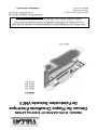
OPERATION AND FIELD INSTALLATION MANUAL
VMCS Heavy Duty Electric Griddle Top
MODELS
VMCS-101
VMCS-102
VMCS-201
VMCS-202
VMCS-101
For additional information on Vulcan or to locate an authorized parts and
service provider in your area, visit our website at www.vulcanequipment.com

- 2 -
TABLE OF CONTENTS
OPERATIONS
Installation…………………………………………………………………………………………...
Electrical specifications…………………………………………………………………………….
Controls……………………………………………………………………………………………...
Raising/lowering griddle top……………………………………………………………………….
Teflon wrap installation………………………………………………………………………….....
Plate gap adjuster…………………………………………………………………………………..
Using the griddle……………………………………………………………………………………
Care and cleaning……..…………………………………………………………………………...
Shutdown……………………………………………………………………………………………
Maintenance………………………………………………………………………………………...
FIELD INSTALLATION ASSEMBLY
Tools required………………………………………………………………………………………
Mounting bracket assembly……………………………………………………………………….
Mounting bracket installation……………………………………………………………………...
Griddle top installation……………………………………………………………………………..
Mounting plate installation…………………………………………………………………………
Bumper stop installation...…..……………………………………………………………………..
Range of motion.……………………………………………………………………………………
Electrical connections and specifications.……………………………………………………….
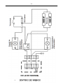
Wiring diagram..…………………………………………………………………………………….
Troubleshooting….…………………………………………………………………………………
3
3
5
6
6
7
8
8
9
10
10
11
11
14
14
17
17
18
19
20

- 3 -
VMCS HEAVY DUTY ELECTRIC GRIDDLE TOP
GENERAL
VMCS Heavy Duty Electric Griddle Tops are produced with quality workmanship and
materials. Proper installation, usage and maintenance of the griddle top will result in
many years of satisfactory performance.
Thoroughly read this entire manual before beginning and carefully follow all of the
instructions provided.
INSTALLATION
Before installing, check the electrical service to make sure it agrees with the
specifications on the rating plate. If the supply and equipment voltages do not agree, do
not proceed with the installation. Contact your dealer or Vulcan-Hart immediately.
INSTALLATION CODES AND STANDARDS
Your Vulcan griddle top must be installed in accordance with:
In the United States of America:
1. State and local codes
2. National Electrical Code ANSI/NFPA – 70 (latest edition) available from The National
Fire Protection Association,1 Batterymarch Park,Quincy, MA 02269.
3. NFPA Standard #96 Vapor Removal from Cooking Equipment, (latest edition) available
From the National Fire Protection Association, Batterymarch Park, Quincy, MA 02269.
In Canada:
1. Local code
2. Canadian Electrical Code C22.1 Part 1 (latest edition) available from the Canadian
Standard Association, 5060 Spectrum Way, Suite 100, Mississauga, Ontario, Canada,
L4W 5N6.
ELECTRICAL SPECIFICATIONS
Model No
Description
Voltage
Power
1 Phase Draw
VMCS-101
FLAT
PLATE
208V
3.6 KW
17.3 A
VMCS-102
240V
15.0 A
VMCS-201
GROOVED
PLATE
208V
17.3 A
VMCS-202
240V
15.0 A

- 4 -
UNPACKING
This griddle top was inspected before leaving the factory. The carrier assumes full responsibility for the
safe delivery upon acceptance of the shipment. Check for possible shipping damage immediately after
receipt.
If the griddle top is found to be damaged, complete the following steps:
1. Carrier must be notified within 5 business days of receipt.
2. Carrier’s local terminal must be notified immediately upon discovery (note time, date, and
who was spoken to), and follow up and confirm with written or electronic communication.
3. All original packing materials must be kept for inspection purposes.
4. The griddle top cannot have been moved, installed, or modified.
5. Notify Vulcan Customer Service immediately at 800-814-2028.
Check that the following have been included:
Bumper stop assembly(see page 16)
o (4) Bumper stop assembly mounting screws
(2) Mounting plates (see page 14)
o (4) M10 mounting plate screws
o (4) M10 mounting plate lock washers
Teflon sheet kit (see page 6)
o (2) Teflon sheets
o (2) Teflon clips
o Teflon bracket
The VMCS mounting bracket (see page 11) is a separate accessory and shipped in
another package. It is recommended that you specify factory mounting of the bracket if
you are purchasing a new griddle with the VMCS Heavy Duty Electric Griddle Top.
The griddle and its parts are hot. Use care when operating, cleaning
or servicing the griddle.
Disconnect power supply and follow lockout / tagout procedures
before cleaning and servicing the appliance.
BEFORE FIRST USE
Remove all packaging material and protective plastic from the unit. It is recommended
that you clean your Vulcan VMCS griddle top thoroughly with a mild soap and water. Wipe
the griddle surface thoroughly with water and wipe dry with a soft clean cloth.
SEASONING THE GRIDDLE
Each time, before turning the unit on, apply high temperature cooking oil – about two
ounces per VMCS top plate. Work the oil into the whole griddle surface.

- 5 -
After cleaning your griddle with chemicals, you should repeat the seasoning procedure for
proper cooking.
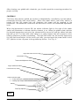
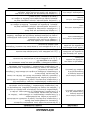
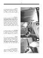
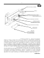
CONTROLS
The heavy duty electric griddle top section is independently controlled by a power switch,
thermostat and high limit cutoff switch. When the power switch (red rocker switch) is
turned ON, the left amber light will illuminate and power will be supplied to the
thermostat. The thermostat cover must be removed to access the thermostat adjustment
knob.
When the thermostat is turned ON, the amber indicator light to the right of the power
switch will illuminate to indicate that the element is on. When the griddle plate reaches
the desired temperature set point, the element will be turned off and the amber indicator
light will go off. The high limit cutoff switch is a safety feature that will cut power to the
heating element to prevent overheating. The high limit switch can be reset by depressing
the high limit reset button. At the end of each day, you must push the power switch to the
OFF position to turn off power to the griddle top section. See Fig. A.
Amber Indicator Lights
Power Light (Left)
Heating Light (Right)
High Limit Reset Access Plug
Thermostat Cover
High Limit Reset Button
Thermostat Adjustment Knob
Handle
Power Switch (Center)
Plate Gap Adjuster
Fig. A

- 6 -
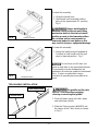
TEFLON WRAP INSTALLATION
To raise the assembly
1. Lift by the handle only
2. Hold handle until assembly holds in
place at the approximate 53° position.
Fig. B
Always hold handle to
maintain control of the unit until lifting
mechanism holds in the desired raised
position or rests in the lowered position.
Do not allow unit to swing upward or
downward under its own power as this
may result in injury or equipment damage.
To lower the assembly
1. Grasp the handle and pull downward.
Continue to hold handle until the unit
stops in lowered position. Fig. C
Do not force unit if it does not
move up and down in the prescribed manner.
The assembly may be damaged by the
application of excessive upward or downward
force. Contact an authorized service
contractor if assembly becomes difficult to
move.
Fig. C
Fig. B
Raised Position
Lowered Position
The griddle and its parts
are hot. Use care when operating,
cleaning or servicing the griddle.
1. Clean off platen using soft cloth, water
and mild soap solution.
2. Slide the Teflon bracket (#944503) into
the sleeve of the Teflon sheet as shown
in Fig. D.
Fig. D
Teflon Bracket
Teflon Sheet Sleeve

- 7 -
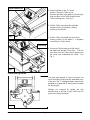
PLATE GAP ADJUSTER
3. Raise the platen to the 53° raised
position. Drape the Teflon sheet
from the right side of the platen by hooking the
front and back of the Teflon bracket to the
Teflon retaining pins. See Fig. E.
4. Pull the Teflon sheet from the right side
around the face of the platen cooking
surface to the left side.
5. Pull the Teflon sheet tight and ensure the
cooking surface of the platen is completely
covered by the Teflon sheet.
6. Secure the Teflon sheet to the left side of
the platen with the two Teflon clips. Push the
clips down over the Teflon sheet, clipping onto
the round rods underneath the sheet. See
Fig. F.
The plate gap adjuster is used to prevent soft
foods from being crushed by the downward force
of the unit. The “1” setting would be used for the
smallest or no gap with “4” being used to create
the largest gap.
Settings are changed by rotating the gap
adjuster body to the left or right until it locks in
place at the desired setpoint.
Fig. E
Fig. F
Teflon Retaining Pin
Teflon Clip
Fig. G

- 8 -
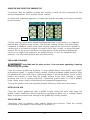
USING THE VMCS ELECTRIC GRIDDLE TOP
To preheat, wipe the griddle top plate with cooking oil and set the thermostats for the
desired temperatures 10-12 minutes before cooking.
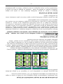
A uniform and systematic approach to loading the griddle will produce the most consistent
product results.
REAR
FRONT
REAR
FRONT
REAR
FRONT
REAR
FRONT
PRODUCT LOADING
The flat cooking surface units feature the Rapid Recovery™ plate which is a composite
material with a stainless steel surface. The grooved cooking surface units have plates
composed of standard, carbon steel. Both cooking surfaces can be scored or dented by
careless use of a spatula or scraper. Be careful not to dent, scratch, or gouge the plate
surface. Do not try to knock off loose food that may be on the spatula by tapping the
corner or the edge of the spatula on the griddle surface. Do not use hardened steel
spatulas. Use mild steel spatulas with rounded corners.
CARE AND CLEANING
The griddle and its parts are hot. Use care when operating, cleaning
or servicing the griddle.
Clean the electric griddle top regularly. A clean griddle always looks better, lasts longer
and performs better. To produce evenly cooked, perfectly browned griddle products keep
the griddle plate clean and free of carbonized grease. Carbonized grease on the surface
hinders the transfer of heat from the griddle surface to the food, resulting in spotty
browning and loss of cooking efficiency. Carbonized grease tends to cling to griddle
foods, giving them a highly unsatisfactory and unappetizing appearance.
To keep the griddle clean and operating at peak efficiency, follow these procedures:
AFTER EACH USE
Clean the electric griddle top with a griddle scraper during the work shift. Keep the
griddle scraper head flat to avoid scratching or gouging the plate. Use a cooking release
agent to prevent product from sticking to the griddle top cooking surface.
ONCE PER DAY
Thoroughly clean all stainless steel exterior panels and surfaces. Clean the cooking
surface with a non-metallic scouring pad (Scotch-Brite™).
Fig. H

- 9 -
ONCE PER WEEK
Clean the griddle surface thoroughly. A mild detergent solution may be used on the plate
surface to help clean it, but be sure the detergent is thoroughly removed by wiping down
with clear water. After removal of detergent from the surface of the plate, the griddle
should be coated with cooking oil according to the instructions in this manual. Clean
stainless steel surfaces with a damp cloth and polish with a soft dry cloth. To remove
discoloration, use a griddle cleaner. If the griddle usage is very high, consider conducting
this weekly cleaning procedure more than once per week.
Do not use a brick or griddle stone for cleaning.
Do not use metallic scouring pads for cleaning.
Do not use a water-jet to clean the griddle.
Do not use chlorine sanitizer in contact with griddle. Contact can cause
discoloration, corrosion and permanent damage.
Do not use cleaning agents including Sodium Hydroxide, which is common in
household oven cleaners. Contact can cause discoloration, corrosion and
permanent damage.
CARE AND CLEANING OF TEFLON WRAP
1. In between cooking runs and during idle periods, the Teflon sheet should be wiped off
with water and a clean soft cloth.
2. After each day the Teflon sheet should be removed from the platen(s), disassembled
and placed in water with mild soap solution (no abrasive or harsh chemical cleaners
should be used). Gently wash both sides of the Teflon sheet and the hardware with the
soft clean cloth in the mild soap solution.
3. Using water, rinse the Teflon sheet and hardware thoroughly on both sides.
4. Dry the Teflon sheet and hardware using a clean soft cloth.
5. Before reassembling the Teflon sheet to the platen, clean the platen as described in
Care and Cleaning section.
SHUTDOWN OF GRIDDLE
1. Set the power switch to the OFF position. This will shut down the griddle top
completely.
2. Leave unit in the raised, 53° position.

- 10 -
EXTENDED SHUTDOWN
1. Set the power switch to the OFF position. This will shut down the griddle top
completely.
2. Leave unit in the raised, 53° position.
3. Apply a light coating of cooking oil on the grooved (steel) plate to inhibit rust.
4. Shut off the main electrical supply
MAINTENANCE
The griddle and its parts are hot. Use care when operating, cleaning
or servicing the griddle.
Disconnect power supply and follow lockout / tagout procedures
before cleaning and servicing the appliance.
LUBRICATION
There are no parts on this unit that require lubrication.
SERVICE AND PARTS INFORMATION
Contact the Authorized Service Contractor in your area to obtain service and parts
information. For a complete listing of Service and Parts depots refer to
www.vulcanequipment.com.
When calling for service the following information should be available from the appliance
serial plate: Model Number, Serial Number and voltage.
FIELD INSTALLATION ASSEMBLY
Contact the authorized service contractor in your area for field installation.
The field installation instructions are prepared for the use of trained service technicians and should only
be used by those who are properly qualified. These instructions are not intended to be all
encompassing. You should read, in its entirety, the installation instructions to determine if you have the
necessary tools, instruments and skills required to perform the procedure. The field installation should
not be attempted if you do not have the necessary tools, instruments and skills.
TOOLS REQUIRED FOR FIELD INSTALLATION
1. #2 Philips head screw driver
2. M10 socket driver
3. 7/16” socket driver
4. Rubber mallet
5. Power drill
6. 7/8” deep well socket wrench
7. (2) large “F” clamps
8. 5/32” drill bits for metal
9. Thread lock compound (Loctite Blue®)
10. ¾” wide masking tape

- 11 -
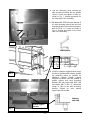
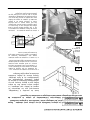
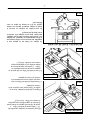
BRACKET ASSEMBLY AND INSTALLATION
The griddle and its parts are hot. Use care when operating, cleaning
or servicing the griddle.
Disconnect power supply and follow lockout / tagout procedures
before cleaning and servicing the appliance.
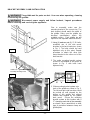
Griddle Top
Assembly Mounting Points
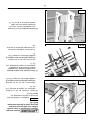
Prior to assembly, make sure the
mounting bracket is the correct size. The
back bracket should match the width of
the griddle. Make sure the griddle top
electrical specifications match the
available service. Each griddle top will
require its own separate electrical service.
1. Using (2) washers and (2) ¼”-28 bolts,
assemble one of the side mount
brackets to the back bracket as shown
in Fig. 1. The bolts should be hand
tightened only at this point. Repeat
procedure to attach the other side
mount bracket to the other end of the
back bracket.
2. The entire mounting bracket system
should be assembled at this point as
shown in Fig. 2 with bolts hand
tightened only.
3. Slide mounting bracket system onto
back of the griddle as shown in Fig. 3.
The left and right side brackets should
be pushed up until stopped by the
bottom of the griddle and pushed
forward until stopped by the griddle
back panel. Secure the mounting
bracket system at this location with a
“F” clamp on each side of the assembly
as shown. Place a wood block or other
type of protection between clamp and
griddle plate.
Fig. 1
Fig. 2
Fig. 3

- 12 -
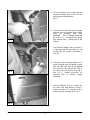
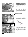
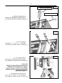
4. Securely tighten the mounting bracket
system assembly bolts at the left and
right side mounting brackets.
Fig. 4.
5. Check that the left and right mounting
brackets have not moved from position
while the assembly bolts were
tightened. The “F” clamps should still
be in place to prevent the assembly
from moving while drilling holes in the
chassis.
Check before drilling holes in chassis, it
is important that the assembly has not
moved from the location prescribed in
step # 3
6. Using the side mounting bracket as a
guide, drill holes into the griddle chassis
with the 5/32” bits only at the highest
hole and the hole nearest the front of
the unit on the side bracket. See Fig. 5
and Fig 6. Repeat procedure for
opposite side of bracket system
assembly.
7. Insert and tighten 10-24 x ½ screws into
the holes that were drilled in step 6.
Repeat procedure for opposite side of
bracket system assembly. See Fig. 6.
Fig. 4
Fig. 5
Fig. 6

- 13 -
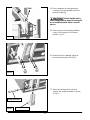
8. Drill the remaining holes through the
side mounting brackets into the griddle
chassis. Insert and tighten screws as
shown in Fig. 7. Repeat procedure for
the other side of the assembly.
9. Drill holes with 5/32” bits from the rear of
the side mounting bracket into the back
mounting bracket and install wall spacer
with (4) 10-24 x ½” screws as shown in
Fig. 8. Repeat procedure for the other
side of the assembly.
Wall Spacer
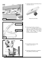
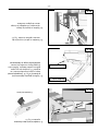
10. Install one bottom support bracket every
two feet of griddle width between griddle
top mounting points as needed for
additional support. Bottom support
brackets should be flush with bottom of
griddle chassis and back mounting
bracket. Drill two holes with 5/32” bits
and attach with 10-24 x 2” screws as
shown in Fig.9 to the back mounting
bracket. Repeat for each bottom
support bracket needed.
Cutaway
side view
Fig. 7
Fig. 8
Fig. 9
Bottom support
bracket

- 14 -
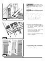
It may be necessary to
angle the griddle and hang one of the
four legs off the edge of the table at a
time to complete step 11. Ensure that
the griddle is safely supported and this
step is accomplished with aid of a
second person.
11. Drill two holes with 5/32” bits through
bottom support brackets and into the
bottom of griddle chassis. Insert and
tighten 10-24 x 2” screws as shown in
Fig.10. Repeat as necessary for all bottom
support brackets.
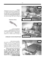
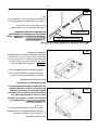
GRIDDLE TOP INSTALLATION
12. Attach masking tape to mounting plate and
slide into position between the griddle back
panel and the top of the selected griddle
top mounting point as shown in
Fig. 11.
13. Use tape to align holes in mounting plate
with holes in griddle top mounting point as
shown in Fig. 12. Tape to hold in position
until installation of griddle top is complete.
Repeat steps 12 and 13 for the bottom
mounting point.
Fig. 10
Fig. 11
Mounting Plate
Griddle top
mounting point
Fig. 12
Mounting Plate

- 15 -
14. Place cardboard or other protective
covering on the gas griddle surface to
prevent scratching.
Ensure that the unit is
safely supported and steps 15 through 20
are accomplished with aid of a second
person.
15. Remove top and rear spring armature
covers. Set into place in the raised
position. Fig. 13.
16. Remove the four retaining clips that
secure the lower pivot rod. Fig 14.
17. Remove the lower pivot rod, then
remove the spring assembly as shown
in Fig 15.
Fig. 13
Fig. 14
Fig. 15
Lower Pivot Rod
Spring Assembly

- 16 -
Ensure that the unit is
safely supported and steps 15 through 20
are accomplished with aid of a second
person.
Apply a thread locking compound
to the mounting bracket screws in steps 18
and 19.
18. Insert and tighten the bottom mounting
bracket screws and washers. Fig.16.
Ensure the mounting screws fully
engage the mounting plate that is
referenced in steps 12 and 13.
19. Set unit to lowered position as shown in
Fig C on page 6. Insert and tighten the
top mounting bracket screws and
washers. Fig.17.
Ensure the mounting screws fully
engage the mounting plate that is
referenced in steps 12 and 13.
Recheck and tighten bottom mounting
screws as necessary.
20. Reverse steps 16 and 17 to reinstall the
spring assembly, lower pivot rod and four
retaining clips. Fig.18
Fig. 16
Fig. 17
Fig. 18

- 17 -
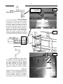
21. Install the bumper stop assembly into top
of armature. Fig. 19
Bumper Stop Assembly
22. Check range of motion as shown in
Fig. 20. The assembly should hold in
place at the raised, 53˚ position and rest
under its own weight in the lowered
position. Refer to page 6 for proper
raising and lowering technique.
23. Reinstall the top and rear spring
armature covers. Fig. 21
24. Repeat proceeding steps as needed for
each griddle top head assembly.
Raised Position
Lowered Position
Fig. 19
Fig. 20
Fig. 21

- 18 -
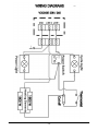
ELECTRICAL CONNECTIONS
Electrical and grounding connections must comply with the
applicable portions of the National Electrical Code and/or other local electrical
codes.
Disconnect the electrical power to the griddle and follow lockout /
tagout procedures.
Since the griddle top is not fused, you must connect to a fused circuit equipped with a
suitable disconnecting means as required by local authorities.
Electrical Connections
1. Remove the small junction box cover plate on the back of the unit. This exposes the
VMCS clamshell griddle line leads.
2. Select a suitable knockout on the sides or bottom of the junction box.
3. Connect the griddle’s line leads to the supply wires with factory supplied wire connectors as shown
in the applicable wiring diagrams.
4. Push the excess wire into the junction box and replace the cover plate. Never operate griddle
without cover in place.
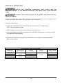
ELECTRICAL SPECIFICATIONS
Model No
Description
Voltage
Power
1 Phase Draw
VMCS-101
FLAT
PLATE
208V
3.6 KW
17.3 A
VMCS-102
240V
15.0 A
VMCS-201
GROOVED
PLATE
208V
17.3 A
VMCS-202
240V
15.0 A

- 19 -

- 20 -
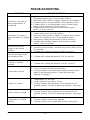
TROUBLESHOOTING
PROBLEM
POSSIBLE CAUSES
Heat does not come on
when power switch is
turned ON
1. Thermostat set too low. Turn to higher setting
2. High limit cutoff switch is tripped – depress reset button.
3. If power switch is not illuminated. Check breaker panel.
4. If power switch is not illuminated, check if main power
supply is disconnected (Call for service).
5. Problem with heating element, thermostat or power
switch. (Call for service)
Heat does not come on
when thermostat is turned
ON
1. Power switch not in the ON position.
2. High limit cutoff switch is tripped – depress reset button.
3. Power not supplied to unit. Check breaker panel.
4. Main power supply disconnected (Call for service).
5. Problem with heating element, thermostat or power
switch. (Call for service)
Unit will not hold or
remain in the raised
position.
1. Not raising high enough. Unit will only hold in place at the
53˚ position.
2. Problem with spring mechanism (Call for service)
Unit will not lower from
the raised position
1. Problem with spring mechanism (Call for service)
Unit will not raise from the
cooking or lowered
position
1. Problem with spring mechanism (Call for service)
Food under-cooked
1. Temperature set too low.
2. Food not cooked for long enough time.
3. Cooking surface not touching or partially touching food
when in the lowered position. Reset the plate gap
adjuster. See page 7.
Food over-cooked
1. Temperature set too high.
2. Food cooked for too long of a time.
3. Cooking surface pressing down too hard when in the
lowered position. Reset the plate gap adjuster. See page
7.
Food is being crushed
1. Cooking surface pressing down too hard when in the
lowered position. Reset the plate gap adjuster. See page
7.
Food sticks to cooking
surface
1. Temperature set too high or too low.
2. Cooking surface needs to be cleaned.
3. Cooking surface not covered with enough cooking oil.
La page est en cours de chargement...
La page est en cours de chargement...
La page est en cours de chargement...
La page est en cours de chargement...
La page est en cours de chargement...
La page est en cours de chargement...
La page est en cours de chargement...
La page est en cours de chargement...
La page est en cours de chargement...
La page est en cours de chargement...
La page est en cours de chargement...
La page est en cours de chargement...
La page est en cours de chargement...
La page est en cours de chargement...
La page est en cours de chargement...
La page est en cours de chargement...
La page est en cours de chargement...
La page est en cours de chargement...
La page est en cours de chargement...
La page est en cours de chargement...
-
 1
1
-
 2
2
-
 3
3
-
 4
4
-
 5
5
-
 6
6
-
 7
7
-
 8
8
-
 9
9
-
 10
10
-
 11
11
-
 12
12
-
 13
13
-
 14
14
-
 15
15
-
 16
16
-
 17
17
-
 18
18
-
 19
19
-
 20
20
-
 21
21
-
 22
22
-
 23
23
-
 24
24
-
 25
25
-
 26
26
-
 27
27
-
 28
28
-
 29
29
-
 30
30
-
 31
31
-
 32
32
-
 33
33
-
 34
34
-
 35
35
-
 36
36
-
 37
37
-
 38
38
-
 39
39
-
 40
40


Vulcan VMCS HD Griddle Top Ele Le manuel du propriétaire
- Catégorie
- Plaques électriques
- Taper
- Le manuel du propriétaire
