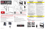
Genie 1028 Operation & Maintenance Manual
- Catégorie
- Porte de garage
- Taper
- Operation & Maintenance Manual
Ce manuel convient également à

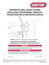
WARNING
To reduce the risk of injury to persons or damage to property, use this opener only with a sectional residential door.
Model 1028
Model 2028
INSTALLER: LEAVE THIS MANUAL WITH HOMEOWNER
HOMEOWNER: SAVE THIS MANUAL FOR FUTURE REFERENCE
BELT/CHAIN DRIVE
OPERATION &
MAINTENANCE
MANUAL
Includes
Intellicode®
Remote Control.
Safe-T-Beam® System
must be installed to close the door.
For use only with residential
sectional overhead garage doors.
Homelink® and Car2U® compatible
©2015 The Genie® Company, the Genie Logo, Intellicode® and Safe-T-Beam®, are trademarks of GMI Holdings, Inc. d/b/a The Genie® Company.
All other trademarks are property of their rightful owners. Consistent with our policy of continuing product improvements, we reserve the right to change product specications without
prior notice or obligations. HomeLink is a registered trademark of Gentex Corporation. Car2U is a registered trademark of Lear Corporation.
38484502553
GARAGE DOOR OPENER MODELS
AVERTISSEMENT
Por réduire le risque de blessures ou de dommages materials, utilisez cet ouvre-porte uniquement pour une porte à section ré sidentielle.
PRE-PROGRAMMED
REMOTE
INCLUDED
FOR QUICK
& EASY
INSTALL
Serial Number Decal
STOP
Need help or have questions?
For answers and assistance,
visit www.GenieCompany.com
or call Customer Service at: 1-800-35-GENIE

Safety Information
Safety Notications ................................................ 1
Important Safety Instructions ............................ 1
Important Installation Instructions .................. 2
Features
Safety Features ........................................................ 3
Opener Features ..................................................... 3
Safe-T-Beam Protection Function ..................... 3
Wall Console Features ........................................... 4
Programming Information
Introduction ............................................................. 5
Overview of Powerhead Controls.....................5
Travel Limits .................................................................
Closing Garage Door (DOWN Limit) ........6
Opening Garage Door (UP Limit) .............. 7
Force Control .................................................... 8
Contact Reverse Test ......................................8
Contact Reverse Adjustment ...................... 8
Remote Control Programming .......................... 9
Optional Programming
Programming Keypad .................................. 10-11
Programming Vehicle Remotes .......................12
Clearing Memory for Remotes ........................13
Installing Battery Backup ...................................13
Maintenance and Adjustments
Important Safety Instructions ..........................14
Regular Maintenance ..........................................15
Remote Battery Replacement ..........................15
Light Bulb Replacement ....................................16
Chain/Belt Tension ...............................................16
Adjustment Guides ..............................................17
Locating Safe-T-Beam
®
........................................18
Wiring Diagram ...................................................18
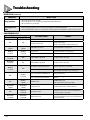
Troubleshooting .......................................... 19-20
Warranty .................................................................21
If you are a homeowner/end user and
need help or have questions:
call 800-35-GENIE.
Or visit: www.GenieCompany.com
Do not return product to the store.
Alternate language manuals available at: www.GenieCompany.com
Idioma alternativo manuales disponibles en: www.GenieCompany.com
Autre langue manuels disponibles à: www.GenieCompany.com

1
Safety Information
OVERVIEW OF POTENTIAL HAZARDS
READ THIS SAFETY INFORMATION
Garage doors are large, heavy objects that move with the help of springs under high tension and electric motors. Since moving objects, springs under tension, and electric
motors can cause injuries, your safety and the safety of others depend on you reading the information in this manual. If you have questions or do not understand the
information presented, call your nearest trained door system technician or visit our website at www.GenieCompany.com.
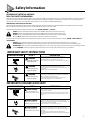
CONVENTIONS USED IN THESE INSTRUCTIONS
The following safety alert symbol and signal words are used throughout this manual to call attention to and identify dierent levels of hazards and special instructions.
This is the safety alert symbol. This symbol alerts you to potential hazards that can kill or hurt you and others.
All safety messages will follow the safety alert symbol and the word
“DANGER”, “WARNING”,
or
“CAUTION”.
•
DANGER
indicates an imminently hazardous situation which, if NOT avoided, will result in death or serious injury.
•
WARNING
indicates a potentially hazardous situation which, if NOT avoided, could result in death or serious injury.
•
CAUTION
indicates a potentially hazardous situation which, if NOT avoided, may result in injury or property damage.
•
The word
NOTE
i
s used to indicate important steps to be followed or important considerations.
Tous les messages concernant la sécurité seront indiqués après un symbole d’alerte de la sécurité et l’une des mentions suivantes “DANGER”, ”AVERTISSEMENT” ou
“MISE EN GARDE”.
• DANGER signale une situation dangereuse imminente qui, si elle n’est pas évitée, risque d’entraîner des blessures graves, voire mortelles.
• AVERTISSEMENT signale une situation potentiellement dangereuse qui, si elle n’est pas évitée, risque d’entraîner la mort ou des blessures graves.
• MISE EN GARDE signale une situation potentiellement dangereuse qui, si elle n’est pas évitée, risque d’entraîner des blessures ou des dommages matériels.
• Le terme REMARQUE est utilisé pour signaler les étapes importantes à suivre ou d’importants éléments à prendre en considération.
IMPORTANT SAFETY INSTRUCTIONS
IMPORTANTES CONSIGNES DE SÉCURITÉ
DANGER POTENTIEL EFFET PRÉVENTION
PORTE EN MOUVEMENT
AVERTISSEMENT
Pourrait entraîner des
blessures graves voire la mort
Utiliser uniquement si la porte est en vue et libre de tout obstacle.
Ne laisser personne se tenir dans l’ouverture de la porte pendant
qu’elle est en mouvement.
Ne pas permettre aux enfants de jouer avec l’opérateur de la porte.
Ne pas faire fonctionner une porte qui bloque ou dont le ressort
est cassé.
CHOC ÉLECTRIQUE
AVERTISSEMENT
Pourrait entraîner des
blessures graves voire la mort
Couper le courant avant d’enlever le couvercle de l’opérateur.
Lorsque le couvercle doit être remplacé, s’assurer que les ls ne sont
ni coincés ni près des pièces mobiles.
L’opérateur doit être correctement mis à la terre.
TENSION ÉLEVÉE RESSORT
AVERTISSEMENT
Pourrait entraîner des
blessures graves voire la mort
Ne pas essayer d’enlever, réparer ni ajuster les ressorts ou
toute autre pièce à laquelle le ressort de la porte est attaché, y
compris blocs de bois, supports en acier, câbles ou autres articles
semblables.
Les réparations et les réglages doivent être eectués par
technicien qualié qui se sert d’outils appropriés et qui respecte les
instructions.
!
!
!
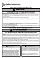
POTENTIAL HAZARD EFFECT PREVENTION
MOVING DOOR
WARNING
Could result in Serious
Injury of Death
Do Not operate unless the doorway is in sight and free of
obstructions. Keep people clear of opening while door is moving.
Do Not allow children to play with the door operator.
Do Not operate a door that jambs or one that has a broken spring.
ELECTRICAL SHOCK
WARNING
Could cause Serious
Injury or Death
Turn o electrical power before removing operator cover.
When replacing the cover, make sure wires are not pinched or near
moving parts.
Operator must be electrically grounded.
HIGH SPRING TENSION
WARNING
Could cause Serious
Injury or Death
Do Not try to remove, repair or adjust springs or anything to which
door spring parts are fastened such as wood block, steel brackets,
cables or any other structure or like item.
Repairs and adjustments must be made by a trained service
representative using proper tools and instructions.
!
!
!

2
Safety Information
IMPORTANTES INSTRUCTIONS D’INSTALLATION
WARNING
!
Operator is equipped with grounded electrical plug for
your protection, and only ts grounded electrical outlets.
DOT NOT alter plug in any way! If your have no grounded
outlets, have one installed by a licensed electrician.
Operator must be properly grounded to prevent personal
injury and equipment damage. NEVER USE AN EXTENSION
CORD! Check local building codes for any requirement
that you must have a permanent hard-wired connection.
Permanent hard-wired connections must be performed by
a licensed electrician using proper tools and instructions.
AVERTISSEMENT
!
L’opérateur, qui est équipé d’une prise électrique mise à la terre
pour votre protection est compatible uniquement avec des
prises électriques mises à la terre. NE PAS modier la che dune
quelconque manière. Si vous n’avez pas de prises mises à la terre,
faites-en installer par un électricien agréé. L’opérateur doit être
correctement mis à la terre pour éviter les blessures corporelles
et des dommages matériels. NE JAMAIS UTILISER DE RALLONGE!
Vériez les codes locaux des bâtiments pour connexions câblées
permanente. Les connexions câblées permanentes doivent
être eectuées par un électricien agréé qui se servira d’outils
appropriés et respectera les consignes.
WARNING
!
TO REDUCE THE RISK OF SEVERE INJURY OR DEATH
READ AND FOLLOW ALL SAFETY, INSTALLATION AND OPERATION INSTRUCTIONS. If you have and questions or do not
understand and instruction, call The Genie Company.
• DO NOT install operator on and improperly balanced door. An improperly balanced door could cause severe injury. Repairs
and adjustments to cables, spring assembly and other hardware must be made by a trained service person using proper
tools and instructions.
• Remove all ropes, and disable all locks connected to the door before installing operator.
• Where possible, install the door opener 7 feet or more above the oor. For products having an emergency release, mount
the emergency release within reach, but at least 6 feet above the oor and avoiding contact with vehicles to avoid
accidental release.
• DO NOT connect the operator to the source of power until instructed to do so.
• Locate the wall control button: A) Within sight of door. B) At a minimum height of 5 feet, so small children cannot reach it.
C) Away from all moving parts of the door.
• Install the entrapment WARNING label next to the wall button or console, in a prominent location. Install the emergency
release handle on the emergency release cord.
• The operator must reverse when the door contacts a 1-1/2 inch high object on the oor at the center of the doorway. This is
about the size of a 2” x 4” board laid at.
AVERTISSEMENT
!
POUR RÉDUIRE LES RISQUES DE BLESSURES GRAVES VOIRE MORTELLES
LIRE ET SUIVRE ATTENTIVEMENT TOUTES LES INSTRUCTIONS D’INSTALLATION ET DE FONCTIONNEMENT AINSI QUE TOUTES LES CONSIGNES DE SÉCURITÉ. Si
vous avez des questions ou si vous ne comprenez pas une instruction, veuillez contacter directement The
Genie Company.
• NE PAS installer l’opérateur sur une porte mal équilibrée. Celle-ci pourrait entraîner de graves blessures. Les réparations et les réglages
des câbles, ensembles de ressort ou tout autre article de quincaillerie doivent être eectués par un professionnel qui se sert d’outils
appropriés et qui respecte les instructions.
• Enlever toutes les cordes et désactiver toutes les verrous de la porte avant l’installer l’opérateur.
• Dans la mesure du possible, installer l’ouvre-porte à 2,1 m ou plus au-dessus du sol. Pour les produits dotés d’un cordon de déclenche-
ment d’urgence, installer le déclenchement d’urgence mais au moins à 1,8 m au-dessus du sol en évitant tout contact avec les véhicules
pour éviter qu’ils ne soient déclenchés accidentellement.
• NE PAS connecter l’opérateur à la source d’alimentation tant que l’instruction n’est pas donnée.
• Repérer la console murale: A) En vue de la porte. B) À une hauteur minimale de 1,5 m an que les jeunes enfants ne puissent pas l’attein-
dre. C) Loin de toutes pièces mobiles de la porte du garage.
• Placer l’étiquette d’AVERTISSEMENT en cas de coinçage à proximité du bouton mural ou de la console de manière à ce qu’elle soit bien en
évidence. Installer la poignée du cordon de déclenchement d’urgence.
• L’opérateur doit s’inverser lorsque la porte entre en contact avec un objet d’une hauteur de 3,8 cm placé sur le sol, au centre de l’ouver-
ture de la porte. Ceci équivaut environ à une planche de 5 x 10 cm posée à plat sur le sol.
IMPORTANT INSTALLATION INSTRUCTIONS

3
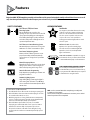
Features
Begin here ONLY AFTER completing assembly and installation of the opener. Review the Assembly and Installation Poster to ensure all
steps have been performed.
V
isit www.GenieCompany.com to download a printable le.
SAFETY FEATURES
Safe-T-Beam® (STB) Non-Contact
Reversing System
Puts an invisible beam across the door
opening. The door stops and reverses to the full
open position if anything passes through the
beam. LED indicator lights on the powerhead
and on the STBs provide self-diagnostics if an
operational problems exists.
Safe-T-Reverse® Contact Reversing System
Automatically stops and reverses a closing door
within two seconds of contact with an object.
Door Detect™ Monitoring System
Monitors the Safe-T-Beam® system to ensure
proper functionality and will automatically
stop and reverse a closing door if a problem is
detected.
Manual Emergency Release
Manually releases door from door opener. Used
during a power failure or other emergency to
allow manual opening and closing of door.
SmartSet
®
Electronic Programming
Easily adjust the programming to set limits and
program new remotes.
Automatic Lighting System
Single bulb lighting system supplies light for
safer evening exits and entries. Turn ON when
door is activated and automatically turns OFF 4
minutes later.
Safe-T-Beam® (STB) FUNCTION
1. The Safe-T-Beam® has no eect on the door during an opening cycle.
2. If the Safe-T-Beam® detects an obstruction when trying to close the
door, it will not allow the door to close.
3. When the garage door is closing, if Safe-T- Beam® is interrupted by
a person or obstacle, the garage door will stop its downward travel
and reverse automatically to its fully opened position.
4. If the Safe-T-Beam® System fails, loses power, or is installed
improperly, press and hold the wall console “open/close” button
until the door reaches its fully closed position. If you release
the “open/close” button on the wall console during the closing
movement, the door will reverse automatically to its fully-opened
position.
OPENER FEATURES
Intellicode®
An encryption system that enhances the security
of the door opener by continuously changing
the access code each time the remote is used.
The door opener responds to each new code
only once. An access code copied from a
working system and tried again, will not control
the door opener.
Wall Console (With selected models)
Operates door opener from inside garage.
The wall console has an indicator light with:
Open/Close, Sure-lock™, and independent
light control buttons.
Home Link® and Car2U® compatible. See page 12
in this manual, refer to your motor vehicle manual
or visit www.GenieCompany.com for instructions.
PRE-PROGRAMMED REMOTE CONTROL
For ease and speed of installation, the remote
included with this opener comes from the factory,
pre-programmed. No additional steps are required
to activate the door using the remote.
OR
NOTE: Use this manual ONLY after completing assembly and
installation of the opener.
Review the Assembly and Installation Instructions poster. Check
that all steps have been completed.

4
Wall Control Features
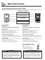
One of the following wall controls will be included.
NOTE:
Wall consoles from other manufacturers may not work with this new opener. Use only the wall control provided with this unit. See warning.
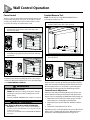
SERIES II WALL CONSOLES
TYPE 1 FEATURES
Indicator Light
Large white button will display Red when wall console is properly
wired and Sure-Lock™ is OFF. When Sure-Lock™ is ON, this light is o.
Open/Close Button
Use this button to open or close garage door. When Sure-Lock™ is
ON the Open/Close button will CLOSE the door only.
NOTE: Constant button pressure in the CLOSE direction will
override STB fault in the powerhead and close door.
Independent Light Control Button
Use this button to powerhead lights ON. Powerhead lighting will remain
ON until this button is pressed again or a door action has been completed.
Sure-Lock™ Button
When Sure-Lock™ is ON, and the door is closed, the powerhead cannot be
activated by the wall console or a remote.
•PressandreleasetoactivateSure-Lock™(redlightgoeso).
•PressandreleasetoturnSure-Lock™OFF(redlightgoeson).
TYPE 3, STANDARD WALL BUTTON
This is a lighted wall button. Press once to move
the door.
If the button is not lighted, check:
-White wire connected to terminal “W”
-Striped wire connected to terminal “B”
Open/Close Button
Opens and closes door from inside garage.
Indicator Light
-Red indicator backlight is ON.
-When Sure-Lock™ in ON, indicator is o.
Sure-Lock™ Button
-LOCK disables controls after door is
completely closed.
-UNLOCK allows controls to work normally.
Independant Light Control Button
Controls door opener lights from inside
garage.
TYPE 2 FEATURES
Indicator Light
Large white button will display Red when wall console is properly
wired and Sure-Lock™ is OFF. When Sure-Lock™ is ON, this light is o.
Open/Close Button
Use this button to open or close garage door. When Sure-Lock™ is
ON the Open/Close button will CLOSE the door only.
NOTE: Constant button pressure in the CLOSE direction will
override STB fault in the powerhead and close door.
Independent Light Control Button
Use this button to powerhead lights ON. Powerhead lighting will remain
ON until this button is pressed again or a door action has been completed.
Sure-Lock™ Button
When Sure-Lock™ is ON, and the door is closed, the powerhead cannot be
activated by the wall console or a remote.
•SlideswitchuptoactivateSure-Lock™(redlightgoeso).
•SlideswitchdowntoturnSure-Lock™OFF(redlightgoeson).
TYPE 1 TYPE 2
WARNING
!
Use of any other wall control can cause unexpected
operation of the door and loss of lighting feature. Locate
wall console within sight of door but far enough from
door to prevent contacting it while operating the console.
Control must be at least 5 feet above the oor to prevent
small children from operating it.
AVERTISSEMENT
!
l’utilisation d’une autre commande murale pourrait des résultats
in attendus de la porte ainsi que le dysfonctionnement de
l’éclairage. Localisez la console murale en vue de la porte et
susamment loin de la porte pour éviter tout contact pendant
l’utilisation de la console. La commande doit être à une hauteur
minimale de 1,5 m au-dessus du sol an que les jeunes enfants ne
puissent pas l’attiendre.

5
Programming Overview
NOTE:
Before programming the operator, check to make sure
there are no objects in the garage door opening.
INTRODUCTION
Now that the garage door opener is installed, follow the
steps in this manual to program the opener so that the door
opens and closes properly and all remote devices operate
correctly. The following steps are a guide to setting opener so
it functions properly.
The following steps list the order of programming the opener’s
functional settings for use.
1. “TRAVEL LIMITS”
2. “FORCE CONTROLS”
3. “REMOTE PROGRAMMING”
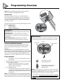
OVERVIEW OF POWERHEAD CONTROLS
This section describes the programming functions of the
opener. Use the following information to understand the
buttons, LED indicators and products used to program
functions.
Powerhead: There are 3 programming buttons and 2 LED
lights on the powerhead. Each of the buttons are used to enter
and complete the setup programming. The LED lights indicate
status or a function change by illuminating ON, OFF, or ON
FLASHING in one of three dierent colors: blue, red or purple.
There are 3 programs:
1. Door Travel Limits.
- This program is used to set how far the door travels
up and down.
2. Remote Programs (default menu)–only required for added
remote control transmitters.
- Describes how to program remotes to sync with
additional remote control devices, wall consoles,
keypads and the powerhead.
3. Force Setting Program.
- This program controls the force applied during the
closing and opening of the door. They are factory set
and will rarely require adjustment only under certain
circumstances.
NOTE: The 3 programming buttons are for programming ONLY.
These buttons should NOT be used to operate the opener once the
Required Programming section has been successfully completed.
Term Denitions:
Travel Limits Programmable setting to adjust how far door
travels up or down.
Force Control refers to how much power is needed to
move (open/close) a particular door and does NOT require
programming.
Remote Programming synchronizes remote devices
(remote, wall console, and keypad) with the powerhead.
Moves door up or down during
programming and advance
through menus.
Enters into and selects
programming menus.
NOTE:
While setting limits, the powerhead has a 30 second time-out period when
none of the three programming buttons have been selected. If you see two solid red
ashing LEDs or if the LEDs ash red three times and then go OFF, you have run out of
time and must go back to the beginning of the travel limit setting step.
• Justremember—the pointed end of the button (like an arrowhead)
points in the direction the carriage will move when that button is
pushed.
DOOR
ORIENTATION
Standing under the opener’s powerhead – facing the door – looking up
– this is the view you will see of the programming buttons and LEDs.
+
PRGM
SET
+
–
PRGM
SET
+
–
PRGM
SET
+
–
+
PRGM
SET
+
–
PRGM
SET
+
–
PRGM
SET
+
–
–
+
PROGRAM
SET
Indicator LED’s
Up Travel
Down Travel
Programming/Menu

6
+
PRGM
SET
+
–
PRGM
SET
+
–
PRGM
SET
+
–
+
PRGM
SET
+
–
PRGM
SET
+
–
PRGM
SET
+
–
+
PRGM
SET
+
–
PRGM
SET
+
–
PRGM
SET
+
–
Programming Information
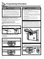
TRAVEL LIMITS
READ AND UNDERSTAND STEPS 2-5 BEFORE
PROCEEDING
Closing Garage Door (Down Limit)
NOTE:
Beginning with garage door in mid travel is recommended but not
necessary.
2. Press and hold the down arrow button (–) for two
seconds or until the long LED comes on blue. (The round
LED stays o.)
Steady Blue
3. Release down arrow button (–) and the long LED will
begin ashing blue. (Round LED still o.)
Flashing Blue
5.Pressandreleasetheprogram/setbutton—bothLEDs
ash blue and then go o.
The DOWN (CLOSED) TRAVEL LIMIT IS NOW PROGRAMMED.
Flashing
Blue
4. Press and hold the down arrow button (–) to begin
closing the garage door. When the garage door is fully
closed, release the down button (–). If it has gone too far
press and release the up button (+) to move the door
up slightly. The door can be moved up or down with the
arrow buttons. The door should rest tightly on the oor.
1. Lift door by hand until carriage engages the turnbuckle
on the chain/belt.
Lever must be UP
DOOR
+
PRGM
SET
+
–
PRGM
SET
+
–
PRGM
SET
+
–
WARNING
!
• Make sure doorway is in full view and clear of obstacles and
people to avoid injury or property damage.
• DO NOT operate this unit from the wall control before LIMITS
are set. Severe damage to the opener could occur.
• The carriage MUST be engaged to turnbuckle BEFORE setting
limits. See installation poster (if provided) or call Customer
Service at 1-800-35-Genie or visit www.GenieCompany.com.
• DO NOT set limits with Power Sentinel attached. AC power
MUST be connected to the opener while setting limits for
proper operation.
AVERTISSEMENT
!
• S’assurer que le passage de la porte est visible et dégagé, à
savoir sans obstacles ni personne an d’éviter toute blessure
potentielle ou dommage matériel.
• NE PAS utiliser cette unité avec la console murale avant
d’avoir réglé les LIMITES. L’ouvre-porte pourrait subir de
sérieux dommages.
• La navette DOIT être engagée dans le chariot AVANT de régler
les limites. Voir le poster d’installation (si fourni) ou appelez le
service clientèle au 1-800-35-Genie ou visitez le site www.
GenieCompany.com.
• NE PAS xer de limites en mode batterie de secours.
L’alimentation CA DOIT être branchée sur l’ouvre-porte,
pendant le réglage des limites, pour assurer un bon
fonctionnement.
NOTE: If carriage has NOT been engaged to carriage, do so now.
Before setting limits:
conrm wall console red indicator
back light is ON. If not illuminated, See page 19 for troubleshooting.
Check STB LED’s: Conrm both LED’s are Illuminated solid. If not
Illuminated solid, see page 18 for troubleshooting.

7
+
PRGM
SET
+
–
PRGM
SET
+
–
PRGM
SET
+
–
+
PRGM
SET
+
–
PRGM
SET
+
–
PRGM
SET
+
–
Programming Information
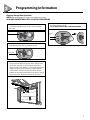
Opening Garage Door (Up Limit)
NOTE:
Beginning with garage door closed is recommended but not necessary.
READ AND UNDERSTAND STEPS 6-9 BEFORE PROCEEDING
6. Press and hold the UP arrow button (+) for two seconds
or until the long LED comes on blue. (The round LED
stays o.)
Steady Blue
Flashing Blue
7. Release UP arrow button (+) and the round LED will
begin ashing blue. (the long LED will go o).
9.Pressandreleasetheprogram/setbutton—bothLEDs
ash blue and then go o.
The UP (OPEN) TRAVEL LIMIT IS NOW PROGRAMMED.
8. Press and hold the up arrow button (+) to begin opening
the garage door. When the garage door is fully opened,
release the up button (+). If it has gone too far press
and release the down button (–) to move the door down
slightly. The door can be moved up or down with the
arrow buttons. Stop the carriage short of the opener
powerhead. It is important for the red cord to be clear of
the powerhead to allow for manual door operation.
+
PRGM
SET
+
–
PRGM
SET
+
–
PRGM
SET
+
–
Flashing
Blue
+
PRGM
SET
+
–
PRGM
SET
+
–
PRGM
SET
+
–

8
or
Wall Control Operation
Force Control
The force controls are automatically set when the wall control is used
for the rst time with garage door opener. The door MUST complete
one full cycle, from full open to full close and then, full close to full
open, before the settings are automatically recorded.
Contact Reverse Test
NOTE:
The limit and Force settings MUST BE COMPLETED before
performing the Contact Reverse Test.
When the door contacts the board, it should stop and reverse
direction within 2 seconds to the fully open position. Red LED
lights on the powerhead will begin to ash with the reversal of
the door. Remove the 2" x 4" board after a successful contact
reversal test. The next cycle will clear the ashing red LEDs.
Contact Reverse Adjustment
If the door stops before contacting the board or if it does not
reverse direction to fully open after contact with the board, it
may be due to an improperly set DOWN limit. Verify settings by:
1. Repeat the “Down Travel Limit” section (page 6) to make
certain the door is closing tight against the oor.
2. Repeat the “Force Control” section on the left to set force
limits.
3. Repeat the “Contact Reverse Test” above.
Repeat this process as needed until the door passes the Contact
Reverse Test. For further help, refer to the “Maintenance and
Adjustment” section/Regular Maintenance. Pages 14-18.
NOTE: Force controls DO NOT require programming. Force limits are factory
set and rarely require adjustments. Making adjustments to these settings is
covered in the “Maintenance and Adjustments” Section of this Manual (pages
14-18).
FORCE CONTROL IS NOW SET.
12. With the garage door open, lay a 2” x 4” board at on
the oor at the center of the door opening.
11. Press and release the wall console Open/Close button
and allow the garage door to travel and stop at the Up
(open) limit.
or
10. Press and release the wall console Open/Close button
and allow the garage door to travel and stop at the
down (closed) limit.
or
13. Close the garage door using the Open/Close button on
the wall control.
WARNING
!
TO AVOID INJURY OR DAMAGE
• NEVER adjust the force settings to adjust for damage,
including an unbalanced door, binding door track or
broken spring.
• Perform a CONTACT REVERSE TEST monthly. See page 8.
AVERTISSEMENT
!
Pour éviter les blessures ou des dommages
• NE JAMAIS régler la force pour compenser des dommages,
y compris une porte mal équilibrée, un rail de porte coinçant
ou des ressorts cassés.
• Tous les mois, EFFECTUEZ LE TEST D’INVERSION AU CONTACT.
Voir page 8.

9
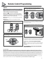
Remote Control Programming
REMOTES
NOTE: THE REMOTE CONTROLS INCLUDED WITH THIS OPENER, HAVE
BEEN PRE-PROGRAMMED AT THE FACTORY FOR YOUR CONVENIENCE.
NOTE:
The following instructions are for remote control transmitters purchased
separately in addition to those provided with this opener, but
can also be used if any remote(s) may require re-programming.
NOTE:
Each programming step has a 30 second time limit for completion
after the function is initiated. After 30 seconds, two LED’s will illuminate RED
indicating time has expired and the step must be re-started. Restart the step as
many times as necessary to complete the programming.
NOTE:
Do NOT hold Remote too close to the Powerhead when programming
Remote buttons.
NOTE:
Each button on each Remote must be programmed separately,
following these steps.
1. Remove the battery’s protective lm from the remote by
pulling it straight out.
2. Press and hold the program button on the opener for two
seconds until the round LED turns blue, then release. The long
purple LED will ash.
3. Slowly press and release the remote button two times. The
opener LEDs will ash and go o, indicating it has been
successfully programmed to the remote.
4. Press and release the same button a third time and door will
open or close.
NOTE:
While programming remote buttons, stand at least 5 feet away from
the powerhead. This ensures you have proper communication between the
remote and the powerhead.
To program the same remote for other garage door openers, repeat
the steps above using one of the other remaining remote buttons.
REPEAT STEPS 1 TO 4 FOR EACH OPENER AND REMOTE
NOTE:
It is possible to press the remote button too quickly or lightly. If the
LEDs do not go o, press the remote button several more times to achieve
conrmation.
BASIC PROGRAMMING IS COMPLETE AND YOUR GARAGE DOOR
OPENER IS READY TO USE.
FCC and IC Certied
This device complies with FCC Part 15 and Industry Canada license exempt RSS standard(s). Operation is subject to the following two conditions: (1)
this devise may not cause interference, and (2) this device must accept any interference, including interference that may cause undesired operation of
the device. This equipment generates, uses and can radiate radio frequency energy and, if not installed and used in accordance with the instructions, may cause
harmful interference to radio communications. However, there is no guarantee that interference will not occur in a particular situation. If this equipment does
cause harmful interference to radio or television reception, which may be determined by turning equipment OFF and ON, the user is encouraged to try and correct
the interference by one or more of the following measures: (a) Re-orient or relocate the receiver antenna, (b) Increase the separation between the opener and
receiver, (c) Connect the opener into an outlet a circuit dierent from that which the receiver is connected, and (d) Consult your local dealer. Any modication or
changes to this equipment which is not expressly approved by the manufacture could void the user’s authority to operate the equipment.
This device complies with the Health Canada’s Safety Code. The installer of this device should ensure that the RF radiation is not emitted in excess of the Health
Canada’s requirement. Information can be acquired at: http://www.hc-sc.gc.ca/ewh-semt/radiation/cons/wi/index-eng.php
+
PRGM
SET
+
–
PRGM
SET
+
–
PRGM
SET
+
–
+
PRGM
SET
+
–
PRGM
SET
+
–
PRGM
SET
+
–
Flashing
Purple

10
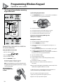
Setting the PIN for the First Time:
1. Press in order the numbers
2. Press the PROGRAM key
3. Type a new PIN (3-8 digits)
4. Press the PROGRAM key again
The keypad is ready to program to an opener.
For use on a Single Door, continue right to 1.
NOTE:
If the keypad lights do not ash and go OFF after
setting PIN, clear the keypad and repeat Step 1; see page
11 for Resetting a PIN.
Locate the Opener’s
Programming Buttons
and LED:
Synchronizing Keypad to Door
1. Press PROGRAM SET button two seconds until the round LED turns
blue, then release. The long purple LED will blink.
2. Key in the new PIN on the keypad.
3. Press Up/Down key and opener LEDs will stay on steady.
4. Press Up/Down key again and opener LEDs turn o.
5. Press Up/Down key a third time and opener runs.
The process of programming ONE keypad to
ONE opener is complete.
Multiple Door Section:
1. Key in the new PIN on the keypad (3-8 digits).
2. Press the PROGRAM key two times.
3. Enter how many total doors the keypad will control (press 2 or 3
accordingly).
4. Press the PROGRAM key.
The keypad is now programmed to receive multiple opener signals.
5. Locate the opener’s programming buttons and LED.
Press PROGRAM SET button two seconds until the round LED turns
blue; then release. The long purple LED will ash.
6. Type the new PIN (3-8 digits).
7. Press the Up/Down key one time.
8. Assign a number to the door that the keypad will operate by
pressing 1-2 or 3.
9. Press that door number a second time.
10. Press that same door number a third time and the door
will operate.
Wait 30 seconds for the keypad to go dark and then start with step 5 for the
additional door/keypad combination as needed.
To add another opener to a keypad that is already programmed to an
opener, follow all the steps in the“Multiple Door Section”.
Please note at Step 8, that the keypad assumes the
original opener programmed to the keypad is opener #1.
Keypads can accept up to three openers.
Keypad Overview:
Programming Wireless Keypad
(Optional on some models)
+
PRGM
SET
+
–
PRGM
SET
+
–
PRGM
SET
+
–
Flashing
Purple
OPEN BATTERY COVER AND PULL PAPER TAB
TO ALLOW OPERATION
+
PRGM
SET
+
–
PRGM
SET
+
–
PRGM
SET
+
–
Tip: Program Keypad before mounting.

11
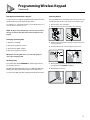
Programming Wireless Keypad
(Continued)
Mounting Keypad
The keypad MUST be mounted within sight of the garage door(s) at
least ve feet above the oor and clear of any moving door part.
1. Remove battery cover and batteries.
2. Drill 3/32” pilot hole for the top mounting screw (included).
3. Install a screw into the pilot hole, leaving a 1/8” gap between the
screw head and wall.
4. Hook the slotted mount, on back of keypad, over the screw.
5. Mark and drill a pilot hole for the bottom screw (included) and
secure keypad to wall (DO NOT overtighten).
6. Reinstall batteries and cover.
Door Operation with Wireless Keypad:
To open and close a single door with the Keyless Entry Pad, enter
the PIN number and press Up/Down Key (enter).
For multiple doors enter the PIN number, press the UP/Down Key once
and enter the door number (1,2 or 3).
NOTE: The Keyless Entry Pad will stay active for 30 seconds and
will stop or start the door with each touch of any button on the
keypad.
Changing an Existing PIN:
1. Enter the current PIN
2. Press the Program key one time
3. Key in the new PIN (3-8 digits)
4. Press the Program key one time
NOTE:
Unlike “Resetting PIN,” there is no need to reprogram your
opener after changing the PIN.
Resetting a PIN:
Press and hold both the PROGRAM key and the Up/Down key
for about ve seconds.
The LED’s will slowly blink and then go out. When the LED stops
blinking, the old programming has been successfully erased.
To create a new PIN, start with “Setting the PIN for the First Time”

12
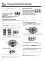
B. Press the chosen HomeLink button for two seconds and release. Press
that same button again for two seconds and release. The long LED
will ash blue and then turn o.
C. Press the HomeLink button a few more times until door moves.
NOTE:
For additional instructions, see the motor vehicle manual,
www.homelink.com or visit www.GenieCompany.com
Step 1 Clear HomeLink
Clear the HomeLink by pressing and
holding down the rst and third buttons
until the indicator on the HomeLink blinks
slow and then fast for 20 seconds; then
release both buttons.
NOTE: Clearing the HomeLink will remove all previously
programmed garage door openers.
Step 2 Train HomeLink to the Genie Remote
Choose the button on the HomeLink that you want to use to open the
door.
NOTE:
Hold the Genie Remote two inches from the HomeLink button.
Hold down the Genie remote button. While holding, press and hold the
chosen HomeLink button.
Hold down both buttons until the indicator on the HomeLink blinks slow
then fast. Once it goes fast, release both buttons.
Step 3 Program HomeLink to the Genie Opener
A. Press and hold the PROGRAM button until the round blue LED is ON.
Release the button. The long purple LED will begin ashing.
Programming HomeLink
®
System
Programming Car2U
®
System
Step 1 Clear Car2U to default settings
The default setting for the Car2U system is:
•Button1=GenieManufacturedOpeners
•Button2=LiftMaster®ManufacturedOpeners
•Button3=WayneDalton®ManufacturedOpeners
A. Press and hold buttons 1 and 3 for 20 seconds or until all three LEDs
begin to ash.
B. Release both buttons. The Car2U system is now set to the Factory De-
fault settings
NOTE:
Clearing the Car2U remote will remove all previously programmed
garage door openers.
Step 2 Program Car2U to the Genie Opener
A. Press and hold the PROGRAM button on the opener until the round
blueLEDisON— releasethebutton.ThelongpurpleLEDwillbegin
ashing.
B. Press the designated Genie Car2U button for two seconds and release.
Press that same button again for two seconds and release. The long LED
will ash blue and then turn o.
C. Press the Car2U button a few times more until door moves.
Step 3 Changing Factory Default Button for a Genie Opener
A. Press and hold buttons 1 & 3 for ONE SECONDandrelease— allthree
LEDs will light solid red.
B. Pressandholdthebutton(2or3)tochangeittoGenie— thecorre-
sponding LED will ash. While continuing to hold that button, press and
release button 1. Press and release button 1 again.
C. Release the button being held step B and wait for the LED to stop ash-
ing. This button is now set for Genie. Repeat Step 2 for second Genie
Opener.
NOTE:
For additional instructions see the motor vehicle manual,
learcar2u.com or visit www.GenieCompany.com
Programming Vehicle Remotes
+
PRGM
SET
+
–
PRGM
SET
+
–
PRGM
SET
+
–
Flashing
Purple
+
PRGM
SET
+
–
PRGM
SET
+
–
PRGM
SET
+
–
Flashing
Purple

13
+
PRGM
SET
+
–
PRGM
SET
+
–
PRGM
SET
+
–
+
PRGM
SET
+
–
PRGM
SET
+
–
PRGM
SET
+
–
+
PRGM
SET
+
–
PRGM
SET
+
–
PRGM
SET
+
–
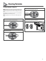
Clearing Remotes
1. Press the PROGRAM/SET button on the powerhead and hold for
two seconds or until the round LED turns blue.
Steady Blue
CLEARING MEMORY OF REMOTES
2.ReleasethePROGRAM/SETbutton—roundLEDgoesoandthe
long LED ashes purple.
Flashing Purple
3. Press and hold the UP (+) and DOWN (–) button at the same
time, until both LEDs ash blue and go o.
Flashing Blue
Flashing Blue
4. To verify that the memory is cleared, press the remote key that
was previously programmed to the opener.
If the memory has been cleared the opener will NOT run.
NOTE:
Clearing memory of remotes from the powerhead will clear ALL
programmed remotes and wireless keypads. The opener will no longer
recognize any signal from any remote device, including a missing remote
device.
All remaining (or recovered) remotes and wireless keypads MUST be
reprogrammed as shown in pages 9,10,12.
NOTE:
The garage door opener will operate normally using the wall
console.

14
Maintenance and Adjustments
For help, call customer service at: 1-800-35-GENIE or visit www.GenieCompany.com
L’opérateur, qui est équipé d’une prise électrique mise à la terre pour
votre protection est compatible uniquement avec des prises
électriques mises à la terre. NE PAS modier la che d’une quelconque
manière. Si vous n’avez pas de prises mises à la terre, faites-en
installer par un électricien agréé. L’opérateur doit être correctement
mis à la terre pour éviter les blessures corporelles et des dommages
matériels. NE JAMAIS UTILISER DE RALLONGE! Vériez les codes
locaux des bâtiments pour toute exigence relative à une connexion
câblée permanente. Les connexions câblées permanentes doivent être
eectuées par un électricien agréé qui se servira d’outils appropriés et
respectera les consignes.
AVERTISSEMENT
L’utilisation d’une autre commande murale pourrait produire des
résultats inattendus de la porte ainsi que le dysfonctionnement
de l’éclairage. Localisez la console murale en vue de la porte et
susamment loin de la porte pour éviter tout contact pendant
l’utilisation de la console. La commande doit être à une hauteur minimale
de 1,5 m au-dessus du sol an que les jeunes enfants ne puissent pas
l’atteindre.
AVERTISSEMENT
WARNING
!
TO REDUCE THE RISK OF SEVERE INJURY OR
DEATH, READ AND FOLLOW ALL INSTRUCTIONS.
1. NEVER let children operate or play with the door controls.
2. Keep remote away from children.
3. ALWAYS keep the moving door in sight and away from
people and objects until door is completely closed. NO ONE
SHOULD CROSS THE PATH OF THE MOVING DOOR.
4. NEVER GO UNDER A STOPPED, PARTIALLY OPEN DOOR.
5. Test opener monthly. The door MUST reverse on contact with
a 1-1/2” high object (or 2” x 4” board laid at) at the center of
the doorway on the oor. After adjusting either the force or
limit of travel, retest door opener. Failure to adjust the opener
properly may cause severe injury or death.
6. When possible, use emergency release only when door is
closed. Use caution when using this release with the door
open. Weak or broken springs are capable of increasing the
rate of door closer and increasing the risk of severe injury or
death.
7. KEEP DOORS PROPERLY BALANCED. See your garage door
Owner’s Manual. An improperly balanced door increases the
risk of severe injury or death. Have a trained door system
technician make repairs to cables, spring assemblies, and
other hardware.
SAVE THESE INSTRUCTIONS
WARNING
!
• Garage door hardware (springs, cables, brackets, pulleys, ect.)
are under extreme pressure and tension.
• DO NOT attempt to repair or adjust door springs or any
hardware, and DO NOT OPERATE garage door automatically
or manually if door is improperly balanced or spring are
broken.
• CONTACT A TRAINED DOOR SYSTEM TECHNICIAN.
WARNING
!
Operator is equipped with grounded electrical plug for your
protection, and only ts grounded electrical outlets. DO NOT
alter plug in any way! If you have no grounded outlets, have
one installed by a licensed electrician. Operator must be
properly grounded to prevent personal injury and equipment
damage. NEVER USE AN EXTENSION CORD! Check local building
codes for any requirement that you must have a permanent hard
wired connection. Permanent hard-wired connections must
be performed by a licensed electrician using proper tools and
instructions.
WARNING
!
Use of any other wall control can cause unexpected operation of
the door and loss of lighting feature. Locate wall console within
sight of the door but far enough from door to prevent contacting
it while operating the console. Control must be at least 5 feet
above the oor to prevent small children from operating it.
IMPORTANT SAFETY INSTRUCTIONS
AVERTISSEMENT
!
POUR RÉDUIRE LE RISQUE DE BLESSURES GRAVES VOIRE MORTELLES,
LIRE ET COMPRENDRE TOUTES LES INSTRUCTIONS.
1. NE JAMAIS permettre aux enfants d’actionner ou de jouer avec les
commandes de la porte.
2. Tenir les télécommandes hors de la portée des enfants.
3. TOUJOURS garder en vue la porte en mouvement et tenir à l’écart
toute personne ou objet jusqu’à ce que la porte soit totalement
fermée. PERSONNE NE DOIT TRAVERSER LA TRAJECTOIRE D’UNE PORTE
EN MOUVEMENT.
4. NE JAMAIS PASSER SOUS UNE PORTE À L’ARRÊT PARTIELLEMENT
OUVERTE.
5. Tester l’ouvre-porte une fois par mois. La porte de garage DOIT inverser
sa course au contact d’un objet de 4 cm (planche de 5 sur 10 cm) posé
à plat sur le sol au centre de l’ouverture de la porte. Après avoir réglé
la force ou la limite de la course, retenter l’ouvre-porte de garage. Un
mauvais réglage de l’ouvre-porte peut entraîner des blessures graves
voire mortelles
6. Utiliser, dans la mesure du possible le déclenchement d’urgence
uniquement lorsque la porte est fermée. Utiliser le déclenchement
d’urgence avec prudence lorsque la porte est ouverte. Des ressorts
faibles ou brisés peuvent faire descendre la porte rapidement ce qui
peut entraîner des blessures graves voire mortelles.
7. VEILLER À CE QUE LA PORTE SOIT CORRECTEMENT ÉQUILIBRÉE.
Consulter le manuel du propriétaire de la porte de garage. Une porte
déséquilibrée pourrait entraîner de graves blessures voire mortelles.
Demander à un technicien spécialisé en système de portes de se
charger des réparations des câbles, des ressorts et de toute autre
quincaillerie.
CONSERVER CES INSTRUCTIONS
IMPORTANTES CONSIGNES DE SÉCURITÉ
AVERTISSEMENT
!
• La quincaillerie de la porte de garage (ressorts, câbles, supports,
poulies, etc.) sont sous des pressions et des tensions extrêmes.
• NE PAS réparer ni régler les ressorts de la porte ou toute autre pièce
de quincaillerie et NE PAS ACTIONNER la porte manuellement ou
automatiquement si elle n’est pas correctement équilibrée ou si des
ressorts sont cassés.
• CONTACTEZ UN TECHNICIEN SPÉCIALISÉ EN SYSTÈME DE PORTES

15
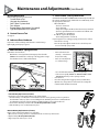
C. Safe-T-Beam
®
(STB) System Check
Check that both the RED and GREEN LEDs are ON steady. This indicates
the system is working properly. If both LEDs are not ON steady, check
the appropriate items below:
• STB red LED ashes.
– Check for obstruction.
– Check alignment.
– Verify wire routing from STBs to STB connection in powerhead
– Check for signal interference from another Safe-T-Beam® unit
(for multiple door installations).
• NoSTBredorgreenLEDdisplayed.
– Check wiring and wire connections
If system appears to be working properly, perform check as follows:
1. Start the door closing.
2. Pass an object through the beam. The door should stop and
reverse to the fully open position.
– Door should remain stationary or move very slowly.
– If door moves quickly, CONTACT A TRAINED DOOR SYSTEM
TECHNICIAN to have your door springs serviced.
• Closethedoor.
• Placethecarriageinthe“engage”position(seeillustration).
• Operatedoorusingremoteorwallcontrol.Thecarriagewill
reattach itself to the drive chain/belt.
Maintenance and Adjustments (continued)
Remote Battery Replacement
(3-button)
Replace remote battery with a CR2032 coin cell battery.
1. Open remote case using a washer or coin that ts into the slot on the top of the remote.
2. Replace battery.
Be sure positive side is UP.
3. Align components and snap case closed.
• Raiseandlowerthedoor
manually—itshouldmove
freely and smoothly.
• Raisedoormanuallyabout
3’ to 4’ feet and let go.
Perform the check as follows:
• With the door closed, pull manual emergency release handle
DOWN and toward the door and let go to disengage the carriage
from the drive chain or belt (see illustration).
D. DOOR BALANCE (spring tension)
E. BATTERY REPLACEMENT
DOOR
Disengage
Engage
Remote Battery Replacement (1-button)
Replace the remote battery with a CR2032 coin cell type battery.
1. Slide the battery cover o (it’s the lower half of the remote’s case) by pressing on the case just below
the indentation at the top of the cover and sliding it down. Alternately, insert a coin or small washer into
the indentation in the front of the case and pry to unlatch the battery cover in order to slide it o.
2. Slide out the old battery and slide in the new. Be sure positive side (+) is UP.
3. Slide the battery cover on until it snaps into place.
Regular Maintenance
Basic monthly maintenance tasks include:
• Contact Reverse Test
• Lubricate door hardware
• Safe-T-Beam® System check
• Door balance
• Remote Battery Replacement (As needed)
• Light Bulb Replacement (As needed)
A. Contact Reverse Test
See page 8.
B. Lubricate Door Hardware
Inspect door rollers and hinges and lubricate as needed using a
light weight general purpose grease.

16
Maintenance and Adjustments (continued)
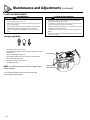
Changing Light Bulbs
1. Disconnect power to door opener.
Open powerhead light cover(s) by pressing down on upper
locking tabs.
• Replace old light bulb(s) with new.
• Use 60 watt incandescent bulbs or the CFL or LED equivalent.
• Close powerhead light cover(s).
2. Reconnect power to door opener.
Test light operation.
NOTE: Use of LED bulbs may reduce the range of your
remote controls.
Visit www.GenieCompany.com for more information and
recommendations for LED bulbs.
F. LIGHT BULB REPLACEMENT
LIGHT BULB
LIGHT COVER
SWINGS OPEN
WARNING
!
• Use extreme caution when working from a ladder or step
stool or serious injury can occur.
• When replacing light cover, make sure wires are not pinched
or near moving parts.
• Use only properly rated incandescent, LED or CFL light bulbs.
• DO NOT use bulbs with a rating greater than 60 Watts.
• Use A19 size light bulbs. DO NOT use bulbs having a short
neck.
AVERTISSEMENT
!
• Faire particulièrement attention lors de travaux eectués
depuis une échelle ou en escabeau.
• En referment le couvercle de l’éclairage, s’assurer que les ls
ne sont ni coincés ni près des pièces mobiles.
• Utilisez uniquement incandescence correctement classé, LED
ou des ampoules uocompactes.
• NE PAS utiliser des ampoules avec une note supérieure à 60
Watts
• Utilisez A19 ampoules de taille. NE PAS utiliser des ampoules
ayant un cou court.

17
Maintenance and Adjustments
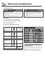
H. ADJUSTMENT GUIDES
Resetting Travel Limits
See pages 6-7-8 to reset travel limits. Force setting and contact
reverse test must be performed in the event of a travel limit change.
NOTE: The opener will not close automatically unless the
Safe-T-Beam® System is installed and Limits are programmed.
–
+
PROGRAM
SET
Press and hold both up and
down arrow buttons until
round LED turns RED, release
buttons. Round BLUE LED will
ash 3 times.
LEDs will now display current UP force setting (See chart).
Press either arrow button until
desired UP force setting is
reached.
See Chart
Once setting is chosen, press
and release. This will lock the
UP force setting.
LEDs will now show current DOWN force setting. (See Chart).
Press either arrow button until
desired DOWN force setting is
reached.
See Chart
Once setting is chosen, press
and release. This will lock the
DOWN force setting.
The LEDs will now turn BLUE then o. This conrms
that both force settings have been set and unit is
ready for normal operation.
Repeat “Learn Force Limits and Contact Reverse Test” page 8
OFF
BLUE
BLUE
OFF
Flashes
3 Times
OFF
RED
BLUE
–
+
PROGRAM
SET
–
+
PROGRAM
SET
–
+
PROGRAM
SET
–
+
PROGRAM
SET
AVERTISSEMENT
!
Pour éviter les blessures ou des dommages
• NE JAMAIS régler la force pour compenser des dommages,
y compris une porte mal équilibrée, un rail de porte coinçant
ou des ressorts cassés.
• Tous les mois, EFFECTUEZ LE TEST D’INVERSION AU CONTACT.
Voir page 8.
WARNING
!
TO AVOID INJURY OR DAMAGE
• NEVER adjust the force settings to adjust for damage,
including an unbalanced door, binding door track or
broken spring.
• Perform a CONTACT REVERSE TEST monthly. See page 8.
Conditions possibly requiring adjustments are:
1. Doors with very sti weather seals.
2. Doors that start down, STOP, and reverse before closing.
3. Doors that start up, but STOP before they completely open
Force Settings
Force settings are pre-programmed at the factory and applied
during the Open/Closed Limit settings steps (see page 8). For
normal use, these settings should not need adjustments with this unit.

18
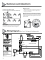
LOCATING SAFE-T-BEAM® PAIRS
Transmitter (RED LED) and Receiver (GREEN LED)
Maintenance and Adjustments
Single Garage Door
• Determinewhichsideofthegaragereceivesdirectsunlight.
• PositiontheSource(RedLED)onthedirectsunlightside.
Multiple Garage Doors
•
NEVER position Safe-T-Beam® modules where signals will cross.
• PlacetheSource(RedLED)Safe-T-Beamsonadjacentdoors
facing in opposite directions.
NOTE:
Direct sunlight creates interference with Safe-T-Beam
®
sensors (Green LED). Sensor modules CAN be positioned further
away from the door opening if necessary to avoid sunlight but
no further o the wall to maintain alignment with the Source
(Red LED) module.
WARNING
AVERTISSEMENT
CHOC ÉLECTRIQUE
OUVERTURE DE COUVERTURE
PEUT PROVOQUER
CHOC ÉLECTRIQUE.
Coupez l'alimentation du
premier match avant de retirer
le couvercle.
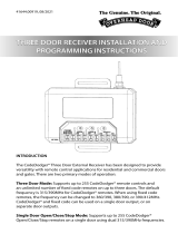
Wiring Diagram
(BasicCircuit—Thisdiagramisforreferenceonly.)
SAFE-T-BEAM
LIGHT
R
GROUND TO
CHASSIS
GREEN w/
YELLOW STRIPE
BLUE
PRINTED CIRCUIT BOARD
STRIPED
WHITE
WALL CONTROL
STB
J7 - TRANSFORMER
PRIMARY
J5 - TRANSFORMER
SECONDARY
STRIPED
WHITE
STRIPED
WHITE
WHITE
WHITE
WHITE - 0 VOLT
YELLOW - 16 VOLT
RED - 24 VOLT
BLACK
BLACK
BLACK
POWER
CORD
BWC
J9 - LIGHT
J8 - AC
POWER
J1 - RED
J2 - BLACK
LINE
VOLTAGE
J3
RED
BLACK
MOTOR
1
2 3
4
La page est en cours de chargement...
La page est en cours de chargement...
La page est en cours de chargement...
La page est en cours de chargement...
-
 1
1
-
 2
2
-
 3
3
-
 4
4
-
 5
5
-
 6
6
-
 7
7
-
 8
8
-
 9
9
-
 10
10
-
 11
11
-
 12
12
-
 13
13
-
 14
14
-
 15
15
-
 16
16
-
 17
17
-
 18
18
-
 19
19
-
 20
20
-
 21
21
-
 22
22
-
 23
23
-
 24
24


Genie 1028 Operation & Maintenance Manual
- Catégorie
- Porte de garage
- Taper
- Operation & Maintenance Manual
- Ce manuel convient également à
dans d''autres langues
- English: Genie 1028
Documents connexes
-
Genie 4164 Mode d'emploi
-
-
-
-
Genie INTELLIG 3024 Manuel utilisateur
-
-
-
-
Autres documents
-
 Overhead door 2029 Programming And Operating Manual
-
Ryobi GD201 Le manuel du propriétaire
-
Lincoln 2010 MKZ Le manuel du propriétaire
-
-
 Genie Company 6072H-BV Le manuel du propriétaire
-
Automatic Technology Garage Door Lock Manuel utilisateur
-
 Genie Company ALKT1-RB Le manuel du propriétaire
-
 Overhead door 890MAX Manuel utilisateur


