Optimus WT-4800 D01E Manuel utilisateur
- Catégorie
- Microphones
- Taper
- Manuel utilisateur

OPERATING INSTRUCTIONS
WIRELESS TUNER WT-4800
Please follow the instructions in this manual to obtain the optimum results from this unit.
We also recommend that you keep this manual handy for future reference.
1. SAFETY PRECAUTIONS ........................... 2
2. GENERAL DESCRIPTION ......................... 4
3. FEATURES ................................................. 4
4. HANDLING PRECAUTIONS ...................... 4
5. NOMENCLATURE AND FUNCTIONS
Front ............................................................ 5
Rear ............................................................. 5
6. OPERATION
6.1. Basic Operation .................................... 6
6.2. Channel/Bank Number Settings ........... 6
6.3. Microphone Sensitivity Adjustment ...... 7
7. HOW TO CHECK AND
DEAL WITH INTERFERENCE
7.1. Order of Actions
(Action Flowchart) ................................. 8
7.2. RF Check Mode Setting ....................... 9
7.3. Channel Detection ................................ 9
7.4. Squelch Adjustment ............................. 9
8. CONNECTION EXAMPLES ..................... 10
9. RACK MOUNTING ................................... 11
10. FIRMWARE VERSION ............................. 11
11. SPECIFICATIONS .................................... 12
Accessories ............................................... 12
TABLE OF CONTENTS
English: page 1
Deutsch: seite 13
Français: page 25
Español: page 37

2
When Installing the Unit
• Do not expose the unit to rain or an environment where it may be splashed by water or other liquids, as
doing so may result in fire or electric shock.
• Use the unit only with the voltage specified on the unit. Using a voltage higher than that which is specified
may result in fire or electric shock.
• Do not cut, kink, otherwise damage nor modify the power supply cord. In addition, avoid using the power
cord in close proximity to heaters, and never place heavy objects -- including the unit itself -- on the power
cord, as doing so may result in fire or electric shock.
• Avoid installing or mounting the unit in unstable locations, such as on a rickety table or a slanted surface.
Doing so may result in the unit falling down and causing personal injury and/or property damage.
• To prevent lightning strikes, install the unit at least five meters away from a lightning rod, and yet within the
protective range (angle of 45°) of the lightning conductor. Lightning strikes may cause a fire, electric shock
or personal injury.
• Since the unit is designed for in-door use, do not install it outdoors. If installed outdoors, the aging of parts
causes the unit to fall off, resulting in personal injury. Also, when it gets wet with rain, there is a danger of
electric shock.
When the Unit is in Use
• Should the following irregularity be found during use, immediately switch off the power, disconnect the power
supply plug from the AC outlet and contact your nearest TOA dealer. Make no further attempt to operate the
unit in this condition as this may cause fire or electric shock.
· If you detect smoke or a strange smell coming from the unit.
· If water or any metallic object gets into the unit
· If the unit falls, or the unit case breaks
· If the power supply cord is damaged (exposure of the core, disconnection, etc.)
· If it is malfunctioning (no tone sounds.)
• Do not place cups, bowls, or other containers of liquid or metallic objects on top of the unit. If they
accidentally spill into the unit, this may cause a fire or electric shock.
• Do not touch the unit's antennas during thunder and lightning, as this may result in electric shock.
1. SAFETY PRECAUTIONS
• Be sure to read the instructions in this section carefully before use.
• Make sure to observe the instructions in this manual as the conventions of safety symbols and messages
regarded as very important precautions are included.
• We also recommend you keep this instruction manual handy for future reference.
Safety Symbol and Message Conventions
Safety symbols and messages described below are used in this manual to prevent bodily injury and property
damage which could result from mishandling. Before operating your product, read this manual first and
understand the safety symbols and messages so you are thoroughly aware of the potential safety hazards.
Indicates a potentially hazardous situation which, if mishandled, could
result in death or serious personal injury.
WARNING

3
When Installing the Unit
• Never plug in nor remove the power supply plug with wet hands, as doing so may cause electric shock.
• When unplugging the power supply cord, be sure to grasp the power supply plug; never pull on the cord
itself. Operating the unit with a damaged power supply cord may cause a fire or electric shock.
• When moving the unit, be sure to remove its power supply cord from the wall outlet. Moving the unit with the
power cord connected to the outlet may cause damage to the power cord, resulting in fire or electric shock.
When removing the power cord, be sure to hold its plug to pull.
• The socket outlet shall be installed near the equipment and shall be easily accessible.
• Avoid installing the unit in humid or dusty locations, in locations exposed to the direct sunlight, near the
heaters, or in locations generating sooty smoke or steam as doing otherwise may result in fire or electric
shock.
• Leave the installation of an antenna to your TOA dealer because the installation requires expert knowledge.
The falling of an antenna may cause electric shock.
When the Unit is in Use
• Do not place heavy objects on the unit as this may cause it to fall or break which may result in personal
injury and/or property damage. In addition, the object itself may fall off and cause injury and/or damage.
• Make sure that the volume control is set to minimum position before power is switched on. Loud noise
produced at high volume when power is switched on can impair hearing.
• Never open the unit case as there are high temperature parts inside the unit, which may cause a burn if
touched. Refer all servicing to your nearest TOA dealer.
• Use the dedicated AC – DC adapter for the unit. Note that the use of other adapter may cause a fire.
• If dust accumulates on the power supply plug or in the wall AC outlet, a fire may result. Clean it periodically.
In addition, insert the plug in the wall outlet securely.
• Switch off the power, and unplug the power supply plug from the AC outlet for safety purposes when
cleaning or leaving the unit unused for 10 days or more. A fire or electric shock may result.
Indicates a potentially hazardous situation which, if mishandled, could
result in moderate or minor personal injury, and/or property damage.
CAUTION

4
2. GENERAL DESCRIPTION
The WT-4800 Wireless Tuner is designed for use on the UHF band, and suitable for vocal or speech
reinforcement applications. It features a compander circuit which minimizes the influence of ambient noise.
3. FEATURES
• 64 different operating frequencies (4 banks x 16 channels)
• Optimized PLL-synthesizer drastically minimizes the oscillation frequency drift resulting from the ambient
temperature changes.
• The Scan function indicates available idle channels and is useful when changing the operating frequency.
• The LCD screen indicates the current operating frequency, as well as RF and AF levels.
• Antenna distribution outputs and audio cascade inputs facilitate connection of another unit to build a dual-
channel system.
• Compact size and high reliability
4. HANDLING PRECAUTIONS
• Make sure that the power switch is switched OFF after use.
• When mounting in an equipment rack, select the position which does not expose the unit to high
temperature.
• When installing, keep the unit as far away as possible from fluorescent lamps, digital equipment, personal
computers, and other equipment which generate high frequency noise.
• Only the same bank wireless systems can be used in the same location. Avoid using the systems in
combination with those of different banks because interference or noise could be generated.
• Wireless tuners to be installed in the same location must differ from each other in channel number. Setting
them for the same channel number could result in noise. Wireless microphones must be identical to wireless
tuners in both bank and channel numbers.
• When using two or more wireless microphones, keep them at least 50 cm away from each other to avoid
malfunctions or noise.
• Keep the wireless microphone at least 3 m away from the receiving antenna. Using the microphone in close
proximity to the antenna could result in malfunctions or noise.
• Be sure to connect at least two receiving antennas (one each for Channels A and B).

5
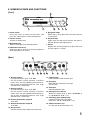
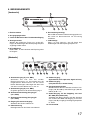
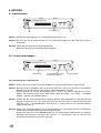
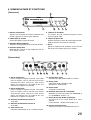
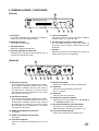
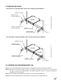
5. NOMENCLATURE AND FUNCTIONS
[Front]
[Rear]
1
2
3
4
5
6
7
11 10
8
9
12
13
14
15 16
18
17
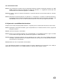
1. Power switch
Press this switch to switch on the power, and
press this switch again to switch off the power.
2. Volume control
Controls an output level.
3. Menu/Enter key
Selects and registers the desired function.
4. Indication selector key
Selects the RF or AF level or receiving frequency
to be displayed on the screen.
5. Reception lamps
Either lamp, A or B, lights when the tuner receives
a radio signal.
6. AF peak lamp
Lights when the output level reaches the point of
about 3 dB below the clipping level.
7. Screen
Displays the receiving frequency or RF or AF level
for each signal in 11 steps.
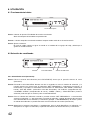
8. Antenna input A
For signal routing A. Input: 75 Ω, BNC
For the wireless system covering a relatively
narrow area, use the supplied two rod antennas,
one of which should be mounted at a 45° angle
outwards from a vertical line.
9. Antenna input B
For signal routing B. Input: 75 Ω, BNC
For the wireless system covering a relatively
narrow area, use the supplied two rod antennas,
one of which should be mounted at a 45° angle
outwards from a vertical line.
10. Antenna distribution output A
75 Ω, BNC
11. Antenna distribution output B
75 Ω, BNC
12. DC input jack
Connect the DC power supply unit to this jack.
13. Cable hanger
Hook the power cable onto this part.
14. AF output
Balanced XLR connector, male type
(Pin #2: Hot)
15. AF output
Unbalanced phone jack
16. AF output level selector
Selects the output level of either –60 dB/600 Ω
or –20 dB/600 Ω. (0 dB = 1 V)
17. AF mixing input (Unbalanced)
Connects to other unit's AF output.
Input level: –20 dB, 10 kΩ (0 dB = 1 V)
18. Communications port
Use this port when connecting a PC.

6
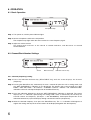
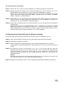
6. OPERATION
6.1. Basic Operation
Step 1. Turn power on, and the power indicator lights.
Step 2. Set the microphone switch to the ON position.
The reception lamp lights when the tuner receives the same frequency signal.
Step 3. Adjust the volume control.
The output level increases as the control is rotated clockwise, and decreases as rotated
counterclockwise.
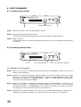
6.2. Channel/Bank Number Settings
6.2.1. Channel (frequency) setting
Step 1. Press the Indication Selector key (RF/AF/NEXT key) until the screen displays the channel
(frequency).
Step 2. Pressing the Menu/Enter key continuously for over a second will place the unit in setting mode, and
the "SET FREQUENCY" indication is first displayed. The display then cycles through the "SET
BANK," "SET SQ LEVEL," "Rf CHECK," "CHANNEL CHECK," "INDEX," and "END SETTING"
indications with each subsequent depression of the Menu/Enter key.
Step 3. Press the Indication Selector key when the "SET FREQUENCY" indication is displayed. The screen
displays the ">>" indication representing the setting mode, which is followed by the currently-set
channel number and frequency. (Example: >> 03 805.000MHz). Subsequent depression of the
Indication Selector key cycles the display through 16 channel numbers (frequencies).
Step 4. Select the desired frequency, then press the Menu/Enter key. The ">>" indication will disappear to
register the setting and only the channel number will be displayed together with the frequency.
13
Reception lamps
Screen
Menu/enter key
Indication selector key

7
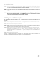
6.2.2. Bank number setting
Step 1. To make the Bank number setting, press the Indication Selector key when the setting mode is "SET
BANK." The screen will display the ">>" setting mode indicator, followed by the currently-set Bank
number. (Example: >>BANK=B)
Step 2. The display cycles through the Bank numbers with each further depression of the Indication Selector
key.
Step 3. Select the desired Bank number. The ">>" setting mode indicator will disappear to register the Bank
number setting and the Bank number will be displayed together with both the channel number and
frequency. (Example: C 03 807.000MHz) In this event, the last channel number before the set Bank
number registration is displayed.
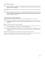
6.3. Microphone Sensitivity Adjustment
Although the audio level is preset by the factory, it can be adjusted depending on the user's voice level.
Step 1. Holding the microphone body, rotate the microphone grip counterclockwise to remove it in the case of
the hand-held microphone, or slide the battery cover down to open it in the case of the lavaliere
microphone.
Step 2. Turn on the power of the tuner and microphone.
Step 3. Adjust the microphone's audio level control using a screwdriver. The sensitivity increases as the
control is rotated clockwise, and decreases as rotated counterclockwise.
Step 4. Set the volume control so that its knob points to the 2 o'clock position. If the AF PEAK lamp remains
lit, readjust the microphone's audio level control so that the lamp only flashes when the signal reaches
its highest peak.
Step 5. Replace the microphone grip (hand-held type) or the battery cover (lavaliere type).
The tuner's AF PEAK lamp lights when the tuner output level reaches the point of about 3 dB below the
clipping level. The PEAK lamp operates in response to the volume control position.

8
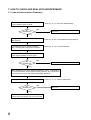
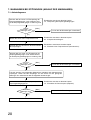
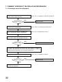
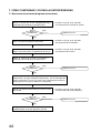
7. HOW TO CHECK AND DEAL WITH INTERFERENCE
7.1. Order of Actions (Action Flowchart)
Place unit in RF check mode and check
signal condition of the channel.
[No]
Any
interference?
[Yes]
[No]
Any
interference?
[Yes]
[No]
Any
interference?
[Yes]
Change bank/channel numbers to those of
idle channels.
It is convenient to use "Channel Check"
when selecting idle bank/channel numbers.
Place unit in RF check mode for a while and
check signal condition of the channel.
Adjust squelch control to limit service area.
When radio interference is still encountered,
consult shop from where unit was purchased.
Refer to p. 9 "7.2. RF Check Mode Setting."
Refer to p. 9 "7.4. Squelch Adjustment."
Use as is.
Refer to p. 6 "6.2. Channel/Bank Number Settings."
Refer to p. 9 "7.3. Channel Detection."
Use as is.
Use as is.
Most interference can be avoided by operations above. If interference
is still encountered, select channel having relatively less interference
using RF check switch, then continue following operations.

9
7.2. RF Check Mode Setting
Step 1. Adjust the volume control to decrease the volume. (Big noise is output if the unit is placed in RF check
mode when no signal is present.)
Step 2. Press the Menu/Enter key for over a second to place the unit in setting mode.
Step 3. Select the item of "Rf CHECK." (Different setting items are displayed on the screen each time the
Menu/Enter key is pressed. Holding down the Menu/Enter key causes the display to cycle through the
setting items in rapid sequence.)
Step 4. Press the Indication selector key to check idle channels by hearing the sound. (Antenna A alternates
with Antenna B with each depression of the Indication key.)
Step 5. After check completion, press the Indication selector key to exit the RF check mode.
7.3. Channel Detection
Step 1. Press the Menu/Enter key for over a second to place the unit in setting mode.
Step 2. Select the item of "CHANNEL CHECK." (Different setting items are displayed on the screen each time
the Menu/Enter key is pressed. Holding down the Menu/Enter key causes the display to cycle through
the items in rapid sequence.)
Step 3. Press the Indication selector key. Channel detection begins and idle channels of the "VACANT Ch=X"
indication are displayed in sequence.
Step 4. Press the Menu/Enter key after check completion and exit channel detection mode.
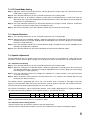
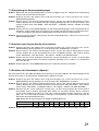
7.4. Squelch Adjustment
The WT-4800 tuner has the squelch function that silences its output in the condition that a radio signal to be
received is a certain level of signal strength. This strength level can be varied by means of the squelch control.
7.4.1. Squelch Level Setting
Step 1. Press the Menu/Enter key for over a second to place the unit in setting mode.
Step 2. Select the setting item of "SET SQ LEVEL." (Different setting items are displayed on the screen each
time the Menu/Enter key is pressed. Pressing the Menu/Enter key causes the display to cycle through
the setting items in rapid sequence.)
Step 3. Press the Indication selector key to display the indication of ">>SQ Level=XX." (The value increases
as the key is pressed.)
Step 4. Select the desired value and press the Menu/Enter key. This registers the selected SQ level and
terminates the SQ level setting.
The squelch control is graduated from "0" to "10". The wireless tuner's sensitivity is the highest and radio
signals can be received in wide areas when the control is in the "0" position, while the "10" position makes the
sensitivity the lowest, limiting signal reception only to narrow areas.
The wireless microphone's signal transmission distance varies largely depending on its ambient conditions.
The table below provides guidelines on the squelch control vs. transmission distance.
Note : Transmission distance when in "0" position is 100%.
7.4.2. Squelch control setting position
• Set the control to the "0" position in locations free from interference.
• Set the control to the position that does not cause any reception loss of wireless microphone signals.
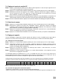
Squelch Control Graduation 0 1 2 3 4 5 6 7 8 9 10
Transmission Distance (%) 100 85 70 60 50 40 35 30 25 20 15

10
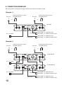
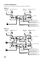
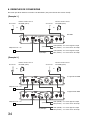
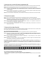
8. CONNECTION EXAMPLES
Be sure to connect at least two receiving antennas (one each for Channels A and B).
[Example 1.]
[Example 2.]
Accessory
or
Wall-mounted wireless antenna
YW-4500 (optional)
Accessory
AC – DC adapter
or
Wall-mounted wireless antenna
YW-4500 (optional)
WT-4800
LINE (LEVEL): To amplifier line input
MIC (LEVEL): To amplifier microphone input
LINE (LEVEL): To amplifier line input
MIC (LEVEL): To amplifier microphone input
Balanced
Unbalanced
Accessory
or
Wall-mounted wireless antenna
YW-4500 (optional)
Accessory
or
Wall-mounted wireless antenna
YW-4500 (optional)
1st WT-4800 unit
2nd WT-4800 unit
AC – DC adapter
AC – DC adapter
LINE (LEVEL): To amplifier line input
MIC (LEVEL): To amplifier microphone input
LINE (LEVEL): To amplifier line input
MIC (LEVEL): To amplifier microphone input
Balanced
Unbalanced

11
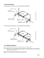
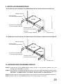
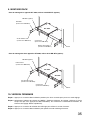
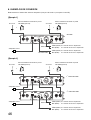
9. RACK MOUNTING
• When mounting one WT-4800 unit, use an optional mounting kit MB-WT1.
WT-4800
Rack mounting screw
(supplied with MB-WT1)
MB-WT1 (optional)
Fiber washer
(supplied with MB-WT1)
Mounting box
(supplied with MB-WT1)
Connector
(supplied with MB-WT1)
Rack
MB-WT2 (optional)
Fiber washer
(supplied with MB-WT2)
Rack mounting screw
(supplied with MB-WT2)
WT-4800
WT-4800
Rack
Connector
(supplied with MB-WT2)
• When mounting two WT-4800 units, use an optional mounting kit MB-WT2.
10. FIRMWARE VERSION
Step 1. Press the Menu/Enter key for over a second to place the unit in setting mode.
Step 2. Select the setting item of "INDEX." (Different setting items are displayed on the screen each time the
Menu/Enter key is pressed. Pressing the Menu/Enter key causes the display to cycle through the
setting items in rapid sequence.)
Step 3. Press the Indication selector key to display the firmware version.
Step 4. Press the Menu/Enter key to exit the firmware display mode.

12
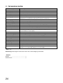
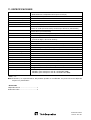
11. SPECIFICATIONS
* 0 dB = 1 V
Note: The design and specifications are subject to change without notice for improvement.
• Accessories
AC – DC adapter ........................................ 1
Rod antenna ............................................... 2
Power Source AC mains (Supplied AC – DC adapter must be used.)
Power Consumption 250 mA (12 V DC)
Receiving Frequency 690 – 865 MHz, UHF
Selectable Channel 64 frequencies
Receiving System Double superheterodyne
Diversity System Space diversity
Mixing Output MIC: –60 dB*/LINE: –20 dB*, 600 Ω
Phone jack (unbalanced), XLR-3-31 type connector (balanced)
Mixing Input –20 dB*, 10 kΩ
Phone jack (unbalanced)
Antenna Input 75Ω, BNC (phantom powering for antenna), 9 V DC, 30 mA (max)
Antenna Output 75Ω, BNC (Gain 0 dB)
Receiving Sensitivity Better than 80 dB, S/N ratio (20 dBµV input, 40 kHz deviation)
Squelch Sensitivity 18 – 40 dBµV variable
Squelch System Using together of noise SQ, carrier SQ and tone SQ
Tone Frequency 32.768 kHz
Indicator Audio (11 steps), RF (11 steps), ANT A/B, Audio (peak)
Channel Check Usable frequencies scanning
Digital Controlled I/O Usable frequencies reading, frequencies input
S/N Ratio Better than 110 dB (A-weight, balanced output)
Harmonic Distortion Less than 1%
Frequency Response 100 – 12,000 Hz, ±3 dB
Other Function Frequency (Bank/Channel) selection by PC
Operating Temperature –10 to +50°C
Finish Resin, black
Dimensions 210 (w) x 44.6 (h) x 180 (d) mm
Weight 700 g
Optional Product Mounting bracket kit: MB-WT1 (for rack mounting one WT-4800 unit)
MB-WT2 (for rack mounting two WT-4800 units)

13
Bedienungsanleitung
Drahtlosempfänger WT-4800
Bitte folgen Sie den Hinweisen in dieser Bedienungsanleitung, um optimale Ergebnisse zu erzielen.
Bewahren Sie die Bedienungsanleitung sorgfältig und zugänglich auf.

14
1. SICHERHEITSHINWEISE ............................................................................. 15
2. ALLGEMEINE BESCHREIBUNG ............................................................... 16
3. LEISTUNGSMERKMALE .............................................................................. 16
4. HINWEISE ZUM BETRIEB ........................................................................... 16
5. BEDIENELEMENTE
Vorderseite ............................................................................................................. 17
Rückseite ................................................................................................................ 17
6. BETRIEB
6.1. Inbetriebnahme ................................................................................................ 18
6.2. Frequenzeinstellungen
6.2.1 Einstellung des Frequenzkanals ............................................................. 18
6.2.2 Einstellung der Frequenzbank ................................................................ 19
6.3. Pegeleinstellung (Empfindlichkeit am Mikrofon einstellen) .............................. 19
7. MAßNAHMEN BEI STÖRUNGEN (ABLAUF DER MAßNAHMEN)
7.1. Ablaufdiagramm .............................................................................................. 20
7.2. Überprüfung der Empfangsbedingungen ........................................................ 21
7.3. Ermitteln freier Frequenzkanäle (Scanfunktion) .............................................. 21
7.4. Einstellen der Rauschsperre (Squelch) ........................................................... 21
8. ANSCHLUßBEISPIELE ................................................................................. 22
9. GESTELLSCHRANKMONTAGE ................................................................ 23
10. ABFRAGE DER PROGRAMM VERSION ................................................ 23
11. TECHNISCHE DATEN .................................................................................... 24
Zubehör .................................................................................................................. 24
INHALTSVERZEICHNIS

15
• Das Gerät darf niemals direktem Regen ausgesetzt werden. Aufstellorte, an dem das Gerät mit Wasser oder
anderen Flüssigkeiten bespritzt werden kann, sind zu vermeiden. Nicht in feuchten oder staubigen Räumen
installieren, nicht direktem Sonnenlicht aussetzen oder in unmittelbarer Umgebung einer Heizung aufstellen.
• Das Gerät darf nur mit der angegebenen Netzspannung betrieben werden.
• Niemals die Kabel knicken, schneiden oder anderweitig beschädigen. Niemals die Kabel in direkter
Umgebung einer Heizung verlegen oder schwere Gegenstände darauf stellen.
• Den Steckernetzteil niemals mit nassen Händen berühren, da dies einen elektrischen Schlag zur Folge
haben kann.
• Niemals am Kabel zerren, um den Netzteil aus der Steckdose zu ziehen. Ein dadurch verursachter
Kurzschluss kann ein Feuer auslösen oder jemand könnte durch einen elektrischen Schlag verletzt werden.
• Installieren Sie das Gerät in einen Mindestabstand von 5 m zum nächstliegenden Blitzableiter.
• Stellen Sie das Gerät auf eine stabile und tragfähige Unterlage.
• Stellen Sie keine Flüssigkeiten auf dem Gerät ab.
• Stellen Sie keine schweren Gegenstände auf dem Gerät ab.
• Beenden Sie den Betrieb sofort, wenn vom Gerät Rauch oder Brandgeruch ausgeht, Wasser oder ein
metallischer Gegenstand eingedrungen sind oder eine Fehlfunktion auftritt (z.B. Tonausfall)
• Service- oder Reparaturarbeiten dürfen nur durch authorisiertes Fachpersonal durchgeführt werden.
• Die Steckdose sollte gut zugänglich in der Nähe des Gerästes installiert sein.
1. SICHERHEITSHINWEISE
Die folgenden Sicherheits- und Warnhinweise sind zu Ihrem Schutz aufgeführt. Bitte lesen Sie diese sorgfältig
durch.
Zeigt eine potenziell gefährliche Situation auf.
Die Nichtbeachtung der Warnhinweise kann zu Verletzungen,
möglicherweise auch mit tödlichem Ausgang, führen.
WARNUNG

16
2. ALLGEMEINE BESCHREIBUNG
Der WT-4800 ist ein UHF-Empfänger für die TOA Drahtlosmikrofone WM-4200 und WM-4300. Er ist sowohl
für Sprach- als auch Gesangsanwendungen konzipiert. Der eingebaute Kompander minimiert den Einfluss
von Störgeräuschen.
3. LEISTUNGSMERKMALE
• 64 verschiedene, wählbare Empfangsfrequenzen (4 Bänke zu je 16 Frequenzkanälen)
• Der optimierte PLL-stabilisierte Empfänger sorgt für hervorragende Frequenzstabilität auch bei wechselnden
Umgebungsbedingungen.
• Mit der eingebauten Suchfunktion werden freie Frequenzen ermittelt und angezeigt.
• Das LCD-Display zeigt die aktuell verwendete Frequenz sowie HF- und Audiosignalpegel an.
• Zwei WT-4800 lassen sich zu einem Zweikanal-System verbinden. Dazu sind die Antenneneingänge auf
Ausgangsanschlüsse durchgeschleift und die entsprechenden Audio-Verbindungen vorgesehen.
• Der WT-4800 ist kompakt aufgebaut und zuverlässig in der Funktion.
4. HINWEISE ZUM BETRIEB
• Stellen Sie sicher, dass der Empfänger nach Gebrauch wieder ausgeschaltet wird.
• Vermeiden Sie hohe Umgebungstemperaturen für den Empfänger. Beachten Sie dies besonders bei der
Montage in Gestellschränken.
• Stellen Sie den Empfänger möglichst weit entfernt von möglichen HF-Störungsquellen wie z.B. PC's,
Leuchtstoffröhren und digitalen Geräten auf.
• Stellen Sie die Drahtlossysteme an einem Ort auf eine gemeinsame Frequenzbank ein. Andernfalls können
Störgeräusche auftreten. Das Mikrofon und der zugeordnete Empfänger müssen auf dieselbe Frequenzbank
und denselben Frequenzkanal eingestellt sein.
• Halten Sie zwischen mehreren Drathlosmikrofonen einen Mindestabstand von 50 cm ein. Sie vermeiden
damit Fehlfunktionen oder Störgeräusche.
• Halten Sie zwischen Empfänger und Drahtlosmikrofon einen Mindestabstand von 3 m ein. Sie vermeiden
damit Fehlfunktionen oder Störgeräusche.
• Schließen Sie an jeden Antenneneingang eine Antenne an.

17
5. BEDIENELEMENTE
[Vorderseite]
[Rückseite]
1
2
3
4
5
6
7
11 10
8
9
12
13
14
15 16
18
17
8. Antenneneingang A (75 Ω, BNC)
Schließen Sie hier eine der beiden
Empfangsantennen an. Verwenden Sie die
mitgelieferten Stabantennen nur bei relativ
kleinen Entfernungen und bringen Sie dann eine
von Ihnen in einem Winkel von ca. 45° an.
9. Antenneneingang B (75 Ω, BNC)
Es gilt das gleiche wie für Antenneneingang A.
10. Antennenweiterleitung (Ausgang) A.
(75 Ω, BNC)
11. Antennenweiterleitung (Ausgang) B.
(75 Ω, BNC)
12. Eingang für Stromversorgung.
Schließen Sie hier das Netzteil an.
13. Kabelsicherung
Befestigen Sie hier das Kabel vom Netzteil.
14. Audio-Ausgang
(Symmetrisch, XLR 3-pol male, Signal an Pin 2)
15. Audio-Ausgang
(Unsymmetrisch, 6.35mm Klinke)
16. Ausgangspegelschalter
Wählen Sie mit diesem Schalter zwischen Line-
Pegel (–20 dB, 600 Ω) oder MIC-Pegel (–60 dB,
600 Ω). 0 dB = 1 V
17. Audio-Eingang für die Kopplung von zwei
WT-4800 (Unsymmetrisch)
Verbinden Sie diesen Eingang mit dem Ausgang
des zweiten WT-4800. Der Eingang ist für Line-
Pegel (–20 dB) ausgelegt. Die Eingangsimpedanz
ist 10 kΩ.
18. PC-Anschluß
1. Ein/Ausschalter
2. Ausgangspegelsteller
3.
Taster für Menüaufruf bzw. Funktionsbestätigung
4. Anzeigeauswahl
Wählen Sie mit diesem Taster aus, ob der HF-
Pegel, der Audio-Pegel oder die Empfangsfrequenz
angezeigt werden sollen.
5. HF-Indikatioren
Beide LED's, A und B leuchten bei Empfang eines
HF-Signals.
6. Aussteuerungsanzeige
Diese LED leuchtet bei Übersteuerungsgefahr auf.
Sie sollte im Normalbetrieb nur kurzzeitig
aufblinken.
7. LCD-Anzeige
Zeigt – je nach Vorwahl – den HF-Pegel, den
Audio-Pegel oder die Empfangsfrequenz an.

18
6. BETRIEB
6.1 Inbetriebnahme
Schritt 1. Schalten Sie den Empfänger ein. Die Betriebsanzeige leuchtet auf.
Schritt 2. Schalten Sie das Drahtlosmikrofon ein. Die Empfangsanzeigen des WT-4800 müssen dann
aufleuchten.
Schritt 3. Stellen Sie den gewünschten Ausgangspegel ein.
Drehen im Uhrzeigersinn erhöht den Ausgangspegel.
6.2. Frequenzeinstellungen
6.2.1 Einstellung des Frequenzkanals
Schritt 1. Drücken Sie so oft auf den Taster [RF/AF/NEXT], bis die Empfangsfrequenz angezeigt wird.
Schritt 2. Schalten Sie den WT-4800 in den Programmiermodus um. Halten Sie dazu den Taster [MENU/
ENTER] solange gedrückt, bis in der Anzeige "SET FREQUENCY" erscheint.
Danach können mit weiteren Betätigungen dieses Tasters die anderen Menüpunkte erreicht
werden. (Die anderen Punkte lauten "SET BANK", "SET SQ LEVEL", "RF CHECK", "CHANNEL
CHECK", "INDEX" und "END SETTING".)
Schritt 3. Drücken Sie den Taster [RF/AF/NEXT], sobald im Display "SET FREQUENCY" angezeigt wird. Die
Anzeige wechselt dann zu der aktuell eingestellten Kanalnummer und der entsprechenden
Frequenz. (z.B. >> 03 805,000 MHz). Das Symbol ">>" zeigt dabei an, dass der WT-4800 im
Programmiermodus ist.
Schritt 4. Drücken Sie anschließend diesen Taster [RF/AF NEXT] so oft, bis der gewünschte Frequenzkanal
mit der entsprechenden Empfangsfrequenz angezeigt wird.
Drücken Sie dann den Taster [MENU/ENTER], um den ausgewählten Frequenzkanal als aktuellen
Empfangsfrequenzkanal festzulegen. Das Symbol ">>" verschwindet, und nur noch der jetzt
aktuelle Empfangsfrequenzkanal wird angezeigt.
13
HF-Indikatioren
LCD-Anzeige
Taster für Menuafruf bzw.
Funktionsbestätigung
Anzeigeauswahl

19
6.2.2 Einstellung der Frequenzbank
Schritt 1. Drücken Sie so oft auf den Taster [RF/AF/NEXT], bis die Empfangsfrequenz angezeigt wird.
Schritt 2. Schalten Sie den WT-4800 in den Programmiermodus um. Halten Sie dazu den Taster
[MENU/ENTER] solange gedrückt, bis in der Anzeige "SET FREQUENCY" erscheint.
Danach können mit weiteren Betätigungen dieses Tasters die anderen Menüpunkte erreicht
werden. (Die anderen Punkte lauten "SET BANK", "SET SQ LEVEL", "RF CHECK", "CHANNEL
CHECK", "INDEX" und "END SETTING".)
Schritt 3. Drücken Sie den Taster [RF/AF/NEXT], sobald im Display "SET BANK" angezeigt wird. Die Anzeige
wechselt dann zu der aktuell eingestellten Frequenzbank. (z.B. >> BANK=B). Das Symbol ">>"
zeigt dabei an, dass der WT-4800 im Programmiermodus ist.
Schritt 4. Drücken Sie anschließend diesen Taster [RF/AF NEXT] so oft, bis die gewünschte Frequenzbank
angezeigt wird.
Drücken Sie dann den Taster [MENU/ENTER], um die ausgewählte Frequenzbank als aktuelle
Empfangsfrequenzbank festzulegen. Das Symbol ">>" verschwindet, und die jetzt aktuelle
Empfangsfrequenzbank wird zusammen mit dem aktuellen Empfangsfrequenzkanal und der
entsprechenden Empfangsfrequenz angezeigt. (z.B. C 03 807,000 MHz)
6.3 Pegeleinstellung (Empfindlichkeit am Mikrofon einstellen)
Um die werkseitig voreingestellte Empfindlichkeit zu verändern, gehen Sie folgendermaßen vor:
Schritt 1. Öffnen Sie das Mikrofon. Beachten Sie hierzu die Bedienungsanleitung lhres Mikrofons.
Schritt 2. Empfänger und Mikrofon einschalten
Schritt 3. Mit dem (mitgelieferten) Schraubendreher die gewünschte Empfindlichkeit (Level) einstellen.
Im Uhrzeigersinn steigt die Empfindlichkeit. In der Position HI ist sie maximal und in der Position LO
minimal.
Schritt 4. Am Empfänger wird der Lautstärkesteller auf ca. 70% (2 Uhr Position) gebracht. Wenn die
Übersteuerungsanzeige (AF Peak) dauerhaft leuchtet, muß am Mikrofon die Empfindlichkeit
verringert werden, solange bis die Anzeige nur noch gelegentlich aufleuchtet. Die
Übersteuerungsanzeige leuchtet bei einem Ausgangspegel der weniger als 3 dB unterhalb des
Clippingpegels liegt.
Hinweis
Die Übersteuerungsanzeige wird durch die Einstellung des Lautstärkestellers beeinflußt. Die
Aussteuerungsanzeige ist nur vom empfangenen Signal abhängig.
Schritt 5. Schließen Sie das Mikrofon wieder, wie in der Bedienungsanleitung lhres Mikrofons beschrieben.

20
7. MAßNAHMEN BEI STÖRUNGEN (ABLAUF DER MAßNAHMEN)
7.1. Ablaufdiagramm
Schalten Sie das Gerät auf "Überprüfung der
Empfangsbedingungen "und" stellen Sie fest,
ob die Empfangsbedingungen in Ordnung sind.
Stellen Sie einen freien Frequenzkanal ein
Ermitteln Sie freie Kanäle mit der Scanfunktion
des Empfängers.
Schalten Sie das Gerät auf "Überprüfung der
Empfangsbedingungen "und" stellen Sie fest,
ob die Empfangsbedingungen in Ordnung sind.
Stellen Sie die Rauschsperre (Squelch) auf die
Empfangsbedingungen ein
Nehmen Sie Kontakt mit lhrem Fachhändler auf.
Einzelheiten entnehmen Sie bitte Kapitel
7.2. "Überpüfung der Empfangsbedingungen"
Einzelheiten entnehmen Sie bitte Kapitel
7.4. "Einstellen der Rauschsperre (Squelch)"
Einzelheiten entnehmen Sie bitte Kapitel
6.2. "Frequenzeinstellungen"
Einzelheiten entnehmen Sie bitte Kapitel
7.3. "Ermitteln freier Frequenzkanäle (Scanfunction)"
Falls Sie trotz der vorangehenden Maßnahmen trotzdem noch Störgeräusche
empfangen, stellen Sie den Empfänger auf den Kanal mit den geringsten
Störungen ein und beachten Sie die folgenden Anweisungen:
[Nein]
Treten
Störungen auf?
[Ja]
Lassen Sie die Einstellungen unverändert
Lassen Sie die Einstellungen unverändert
Lassen Sie die Einstellungen unverändert
[Nein]
Treten
Störungen auf?
[Ja]
[Nein]
Treten
Störungen auf?
[Ja]
La page charge ...
La page charge ...
La page charge ...
La page charge ...
La page charge ...
La page charge ...
La page charge ...
La page charge ...
La page charge ...
La page charge ...
La page charge ...
La page charge ...
La page charge ...
La page charge ...
La page charge ...
La page charge ...
La page charge ...
La page charge ...
La page charge ...
La page charge ...
La page charge ...
La page charge ...
La page charge ...
La page charge ...
La page charge ...
La page charge ...
La page charge ...
La page charge ...
-
 1
1
-
 2
2
-
 3
3
-
 4
4
-
 5
5
-
 6
6
-
 7
7
-
 8
8
-
 9
9
-
 10
10
-
 11
11
-
 12
12
-
 13
13
-
 14
14
-
 15
15
-
 16
16
-
 17
17
-
 18
18
-
 19
19
-
 20
20
-
 21
21
-
 22
22
-
 23
23
-
 24
24
-
 25
25
-
 26
26
-
 27
27
-
 28
28
-
 29
29
-
 30
30
-
 31
31
-
 32
32
-
 33
33
-
 34
34
-
 35
35
-
 36
36
-
 37
37
-
 38
38
-
 39
39
-
 40
40
-
 41
41
-
 42
42
-
 43
43
-
 44
44
-
 45
45
-
 46
46
-
 47
47
-
 48
48


Optimus WT-4800 D01E Manuel utilisateur
- Catégorie
- Microphones
- Taper
- Manuel utilisateur
dans d''autres langues
- English: Optimus WT-4800 D01E User manual
- español: Optimus WT-4800 D01E Manual de usuario
- Deutsch: Optimus WT-4800 D01E Benutzerhandbuch
Documents connexes
Autres documents
-
TOA WS-5325M Manuel utilisateur
-
-
TOA WT-5805 Manuel utilisateur
-
Sennheiser G2 Manuel utilisateur
-
-
Harris XL-200P Series Manuel utilisateur
-
Gemini Headphones UZ-1128 Manuel utilisateur
-
-
LD Systems WIN 42 BPG Manuel utilisateur
-
TOA WD-4800 US Manuel utilisateur